Contents
1. Objective
2. NRF24L01
3. Hello World with nRF24L01
4. Electric Skateboard
5. Result
6. References
7. Download
1. Objective
In this network chapter, we are learning how to use bluetooth and the reciever for an electric skateboard remote control.
There are going to be two boards made. One is in the skateboard to run the brushless motor and revive the data from the other board. The second board is to read the potentiometer in the joystick and then send the value to the first board.
2. NRF24L01
NRF24L01 is a radio module that I use to control an electric skateboard.

2.1 Remote control
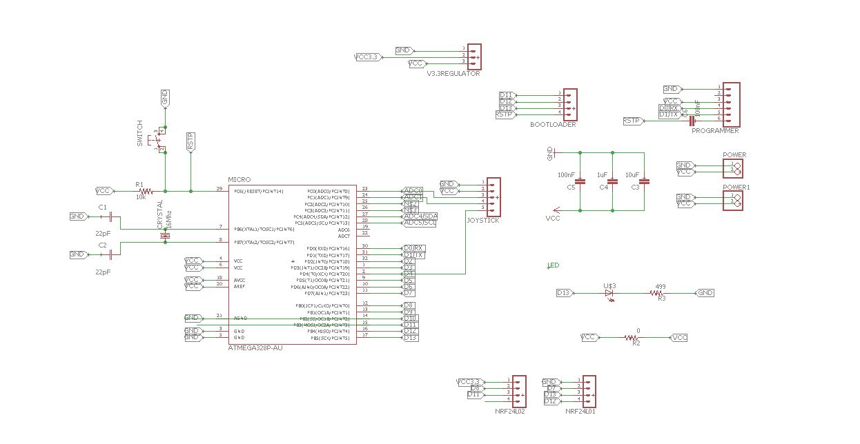
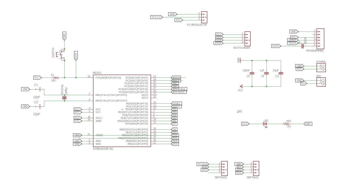
First of all, I started by modifying a satshakit, https://github.com/satshas/satshakit. I removed all the unessary parts and only keep the pins that I need to use it, such as the pins to bootloader, connect the FTDI and the input for the joystick.

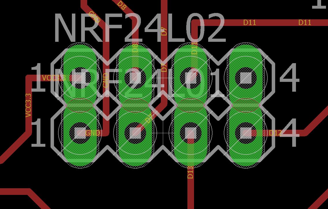
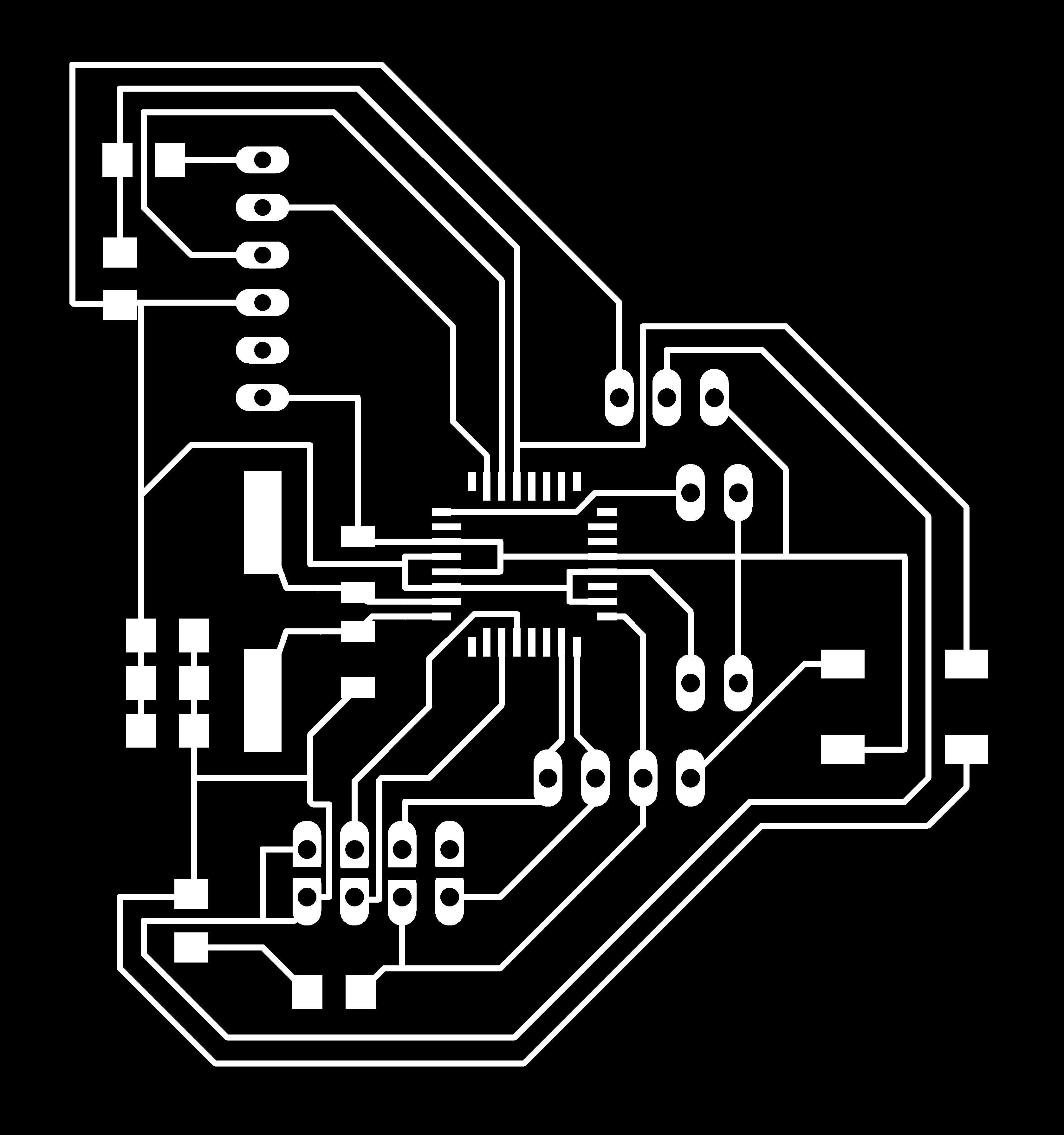
This is the PCB for the remote control.
After milling the PCB, we will need to bootloader the board and then upload the program using the FTDI. Do not forget to connect the joystick.

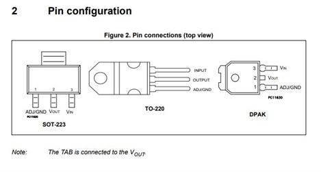
The radio module, nRF24L01 needs 3.3v to power, this is why I need a voltage regulator and this is the pin connection diagram from the data sheet that I have found.
The board pins are flipped accidentally because I didn't double check the connections but I have fixed the issues in the download part. This is a reason the picture use a jumper cables.
Remote control connection
Board to NRF24L01

Connect the battery to 5v vcc and gnd, then it is ready to use.
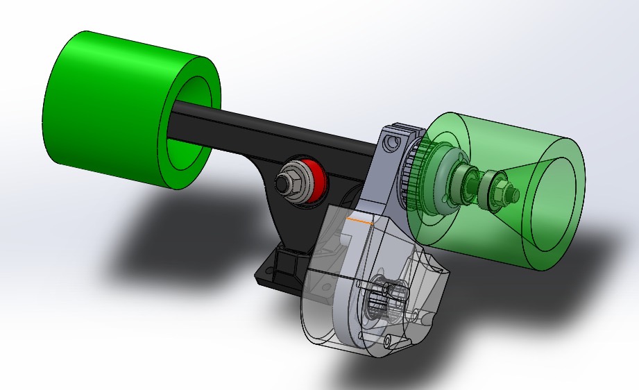
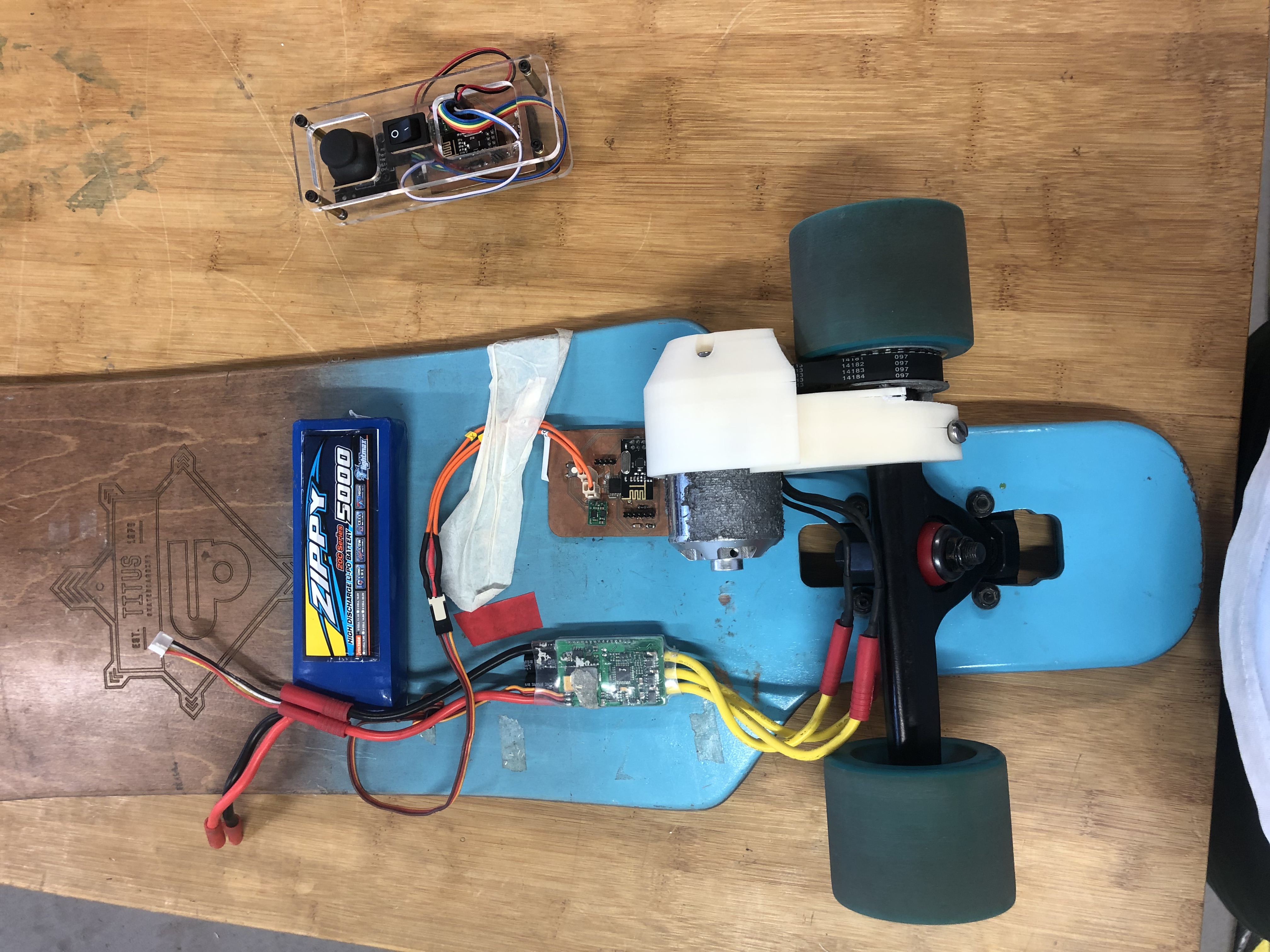
2.2 Main PCB Board
In the main board needs 1 pwm pin signal to drive the Electronic Speed Control and the connection to the radio module.

This is the baord for the main board of the skate board.
Save as this image to mill the PCB.

Save as this image to cut the PCB.
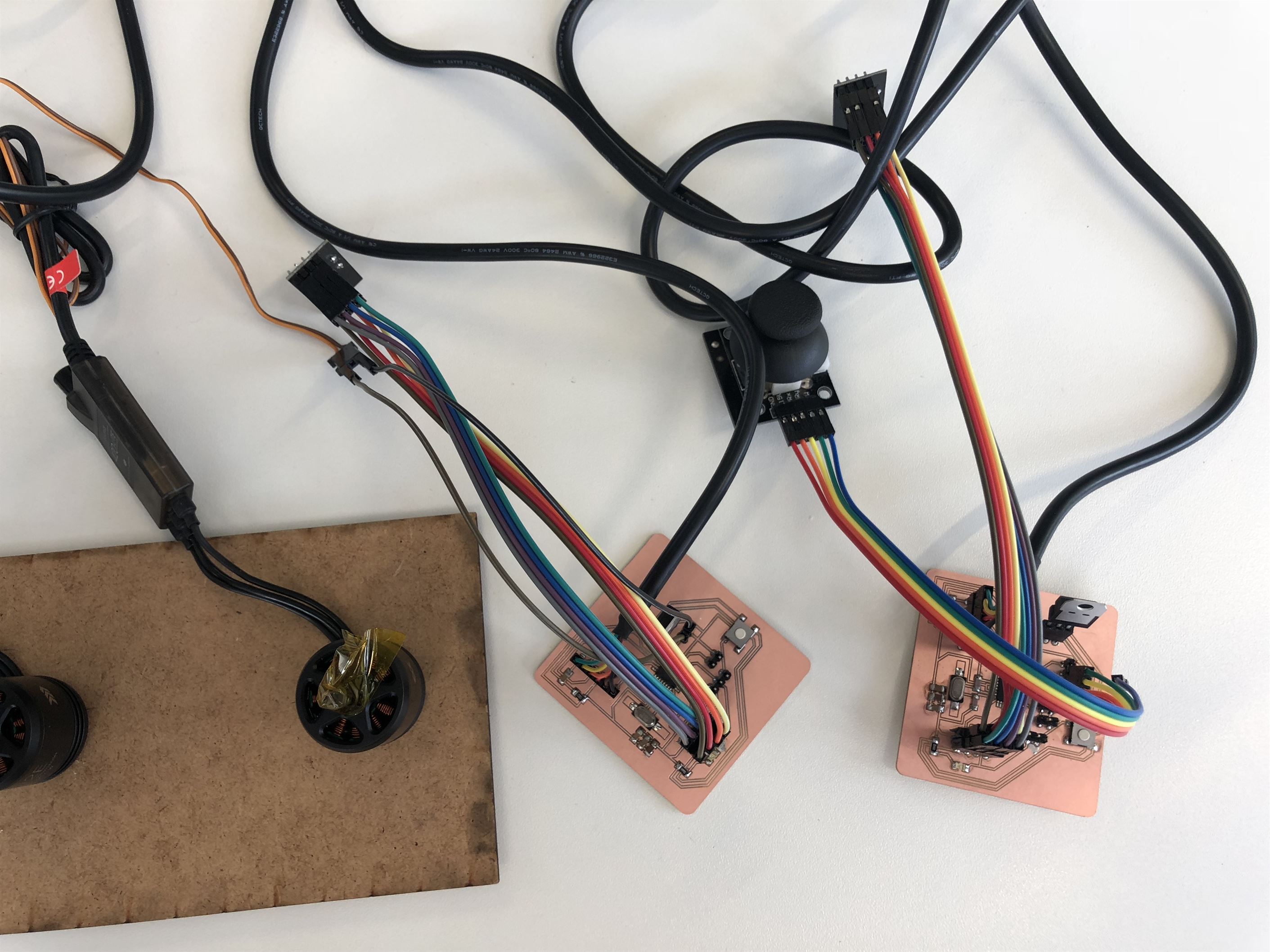
Connect the radio module, ESC and voltage regulator to the main board.
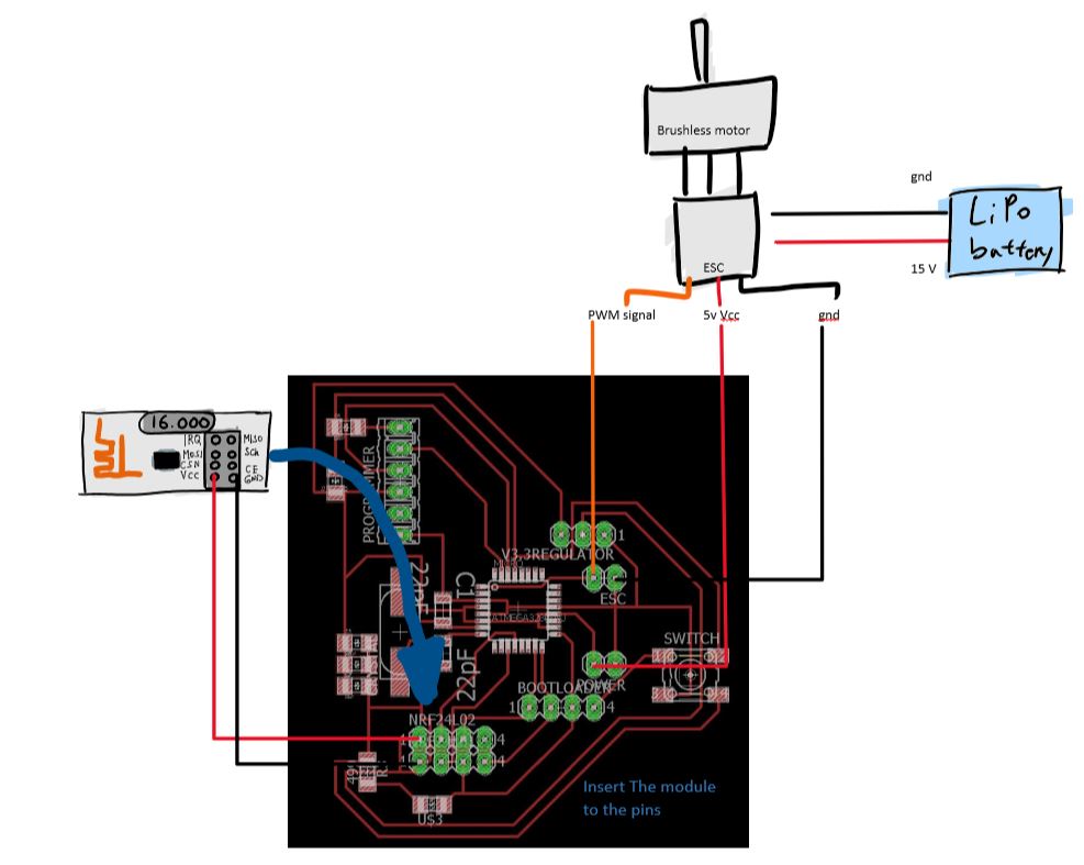
Main board connections
Board to NRF24L01
3. Hello World with nRF24L01
nRF24L01+ (2.4 GHz ISM)Before started to control the brushless motor, it is good to always check the system with a hello world code to make sure everything is working.
3.1 Transmiter
/*
*
* Library: TMRh20/RF24, https://github.com/tmrh20/RF24/
*/
#include <SPI.h>
#include <nRF24L01.h>
#include <RF24.h>
RF24 radio(7, 8); // CE, CSN
const byte address[6] = "00001";
void setup() {
  radio.begin();
  radio.openWritingPipe(address);
  radio.setPALevel(RF24_PA_MIN);
  radio.stopListening();
}
void loop() {
  const char text[] = "Hello World";
  radio.write(&text, sizeof(text));
  delay(1000);
}
Upload this program to the remote control.
3.2 Reciever
/*
*
* Library: TMRh20/RF24, https://github.com/tmrh20/RF24/
*/
#include <SPI.h>
#include <nRF24L01.h>
#include <RF24.h>
RF24 radio(7, 8); // CE, CSN
const byte address[6] = "00001";
void setup() {
  Serial.begin(9600);
  radio.begin();
  radio.openReadingPipe(0, address);
  radio.setPALevel(RF24_PA_MIN);
  radio.startListening();

}
void loop() {
  if (radio.available()) {
    char text[32] = "";
    radio.read(&text, sizeof(text));
    Serial.println(text);
  }
}
Upload this program to the main board of the skate baord.
4. Electric Skateboard
4.2 Program
4.2.1 Remote control program
This is the code that I programmed for the remote contro. Basically it is connected to the radio module and a joystick. The joystick is for the input where it sends the value to another board through the radio mdoule.
/*
* Transimiter Code with joystick
*
* by Marcello Tania
*
*/

#include <SoftwareSerial.h>
#include <SPI.h>
#include <nRF24L01.h>
#include <RF24.h>

RF24 radio(7, 8); // CE, CSN

const byte address[6] = "00001";

// input pins
const byte Xin      = A0;   // X input connected to A0
const byte Yin      = A1;   // Y input connected to A1
const byte Buttonin = 4;    // pushbuttom input connected to Digital pin 7


// output pins (only if necessary)
int ledPin  = 13;        // select the pin for the blue LED PB0


// state machine
int state       = 0;


//threshold because of physical limitation 533 centre of joystick at x axis
const int THRESHOLD_LOW_X   = 523;
const int THRESHOLD_HIGH_X  = 543;

//threshold because of physical limitation 522 centre of joystick at y axis
const int THRESHOLD_LOW_Y   = 512;
const int THRESHOLD_HIGH_Y  = 532;

// joystick value
int sensorValuex,sensorValuey, buttonState;

void setup() {
  // put your setup code here, to run once:
  Serial.begin(9600);               // initialize serial communication

  //Input
  pinMode (Buttonin, INPUT_PULLUP); // internal pull up resistor
  pinMode (Xin, INPUT);             // initialize Xin as INPUT
  pinMode (Yin, INPUT);             // initialize YZin as INPUT

  //Output
  pinMode(ledPin, OUTPUT);      // declare the ledPin as an OUTPUT
  digitalWrite(ledPin, HIGH);   // turn the LED on (HIGH is the voltage level)

  //radio setup NRF24L01
  radio.begin();
  radio.openWritingPipe(address);
  radio.setPALevel(RF24_PA_MIN);
  radio.stopListening();

}

void loop() {
  // put your main code here, to run repeatedly:


  readPotentiometer();

}

void readPotentiometer(){
  sensorValuex  = analogRead(Xin);
  sensorValuey  = analogRead(Yin);
  buttonState   = digitalRead(Buttonin);

  // send the sensor Value of x through radio
  radio.write(&sensorValuex, sizeof(sensorValuex));
  delay(5);
  /*
  Serial.print("  Axis XY");
  Serial.print("  X:");
  Serial.print(sensorValuex);
  Serial.print("  Y:");
  Serial.println(sensorValuey);
  */
}
4.2.2 Reciever program
This should be upload on the skateboard PCB board where it recive the value from the remote and then control the brushless motor with an elecronics speed controller.
/*
* Receiver Code
*
* by Marcello Tania
*
* Library: TMRh20/RF24, https://github.com/tmrh20/RF24/
* Power up the ESC by turning on the power supply (15.2-16V),
*/
#include <SPI.h>
//#include <nRF24L01.h>
#include <RF24.h	>
#include <Servo.h>

Servo esc;

RF24 radio(7, 8); // CE, CSN
const byte address[6] = "00001";
void setup() {
  Serial.begin(9600);

  //esc signal pinout
  esc.attach(3);

  radio.begin();
  radio.openReadingPipe(0, address);
  radio.setPALevel(RF24_PA_MIN);
  radio.startListening();

  //indicator that the microcontroller is on
  pinMode(13, OUTPUT);
  digitalWrite(13, HIGH);   // turn the LED on (HIGH is the voltage level)

  Serial.println("Initializing ESC");
  //initializing the esc
  esc.write(1023);
  delay(2000);
  Serial.println("You should hear a beeping sound ");
  esc.write(534);
  delay(2000);
  esc.write(53);
  Serial.println("The ESC will play a tone. ");
  Serial.println("Reciever is ready");
}
void loop() {
  if (radio.available()) {

    int potentiometer;
    radio.read(&potentiometer, sizeof(potentiometer));
    potentiometer =potentiometer- 230;


    potentiometer = map(potentiometer, 0, 1023, 0, 179);
    //290 is stop
    Serial.println(potentiometer);
    esc.write(potentiometer);
  }
}
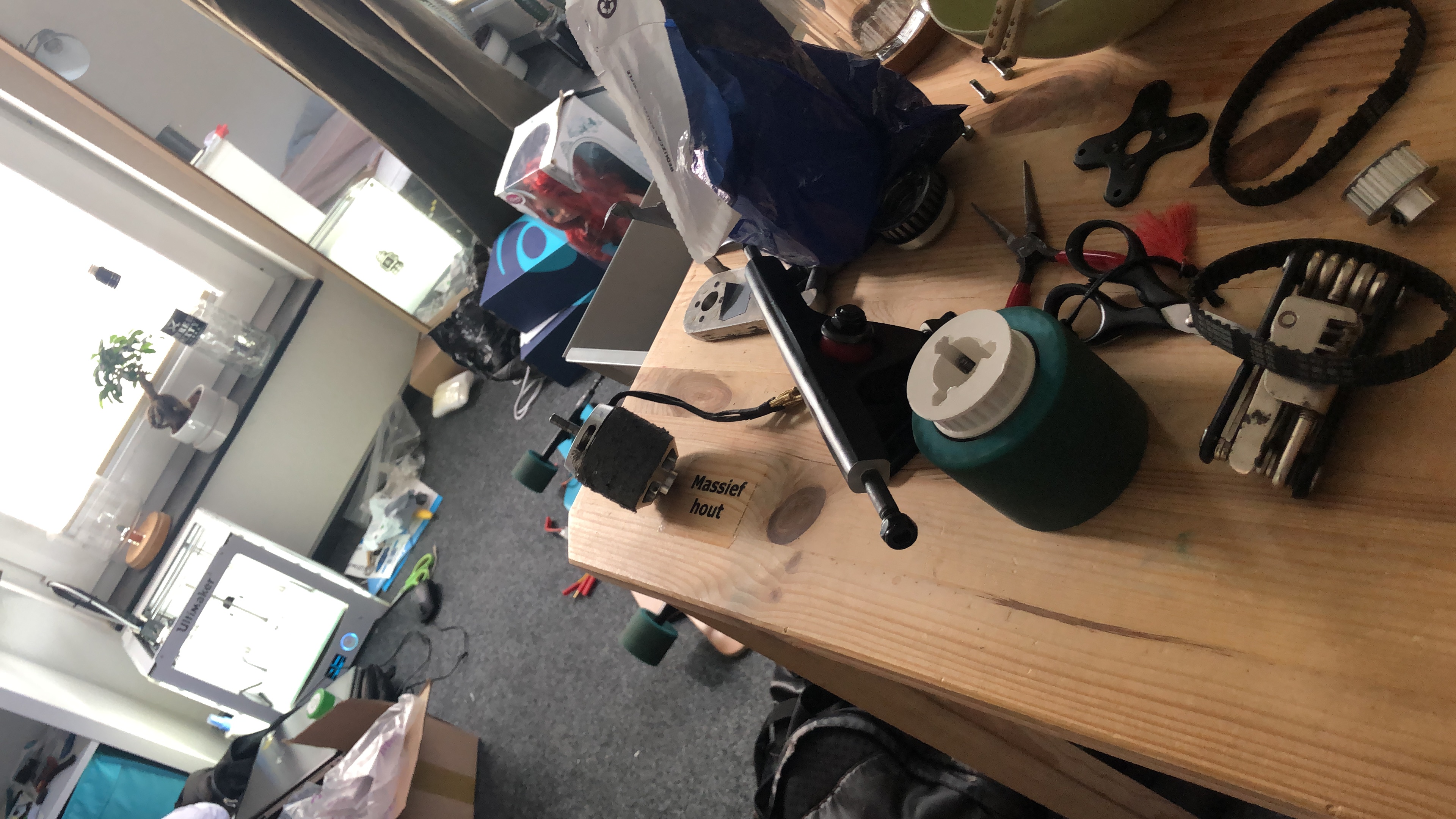
5. Result

The first trial of my electric skateboard.
A trial without a person.
The gohst version!
Final result.
Based on the experiment I did, it runs with a maximum speed of 28km/h!

6. Update
This is the update after I finished FabAcademy in 2018, I kept updating my electric skate board by designing the chasis and PCB using my own DIY remote control in 2019.