Contents
1. Objective
2. 3D CADr
3. 2D Drawing
4. Assembly
5. Result
6. Reference
7. Download
1. Objective
In this assignment, we were dividing and design our task for building a plotte and my task is to work on the end effector. The goal is to be able move the machine manually.
1.1 Concept
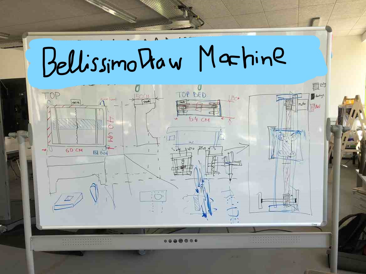
After collecting some idea and brainstroming with my team : Cristian Plugariand Emir Rustamov. We have agreed to devide our task and we need to model them in the 3D CAD software. The difficult part is to communicate so we could assembly all the parts fitly together.
2. 3D CAD
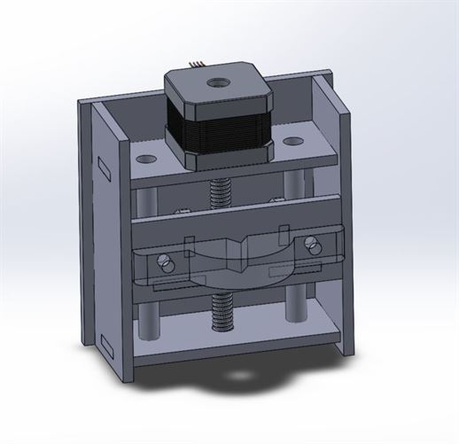
I was using solidworks to design this z-axis movement.
The coupler is used for connecting the gear screw and the stepper motor. It is also good for aligning the motor and the linear gear screw.
The two rods are guiding and support the bed for placing the end tool. It works as a linear guide to make the movement more stable.
3. 2D Drawing
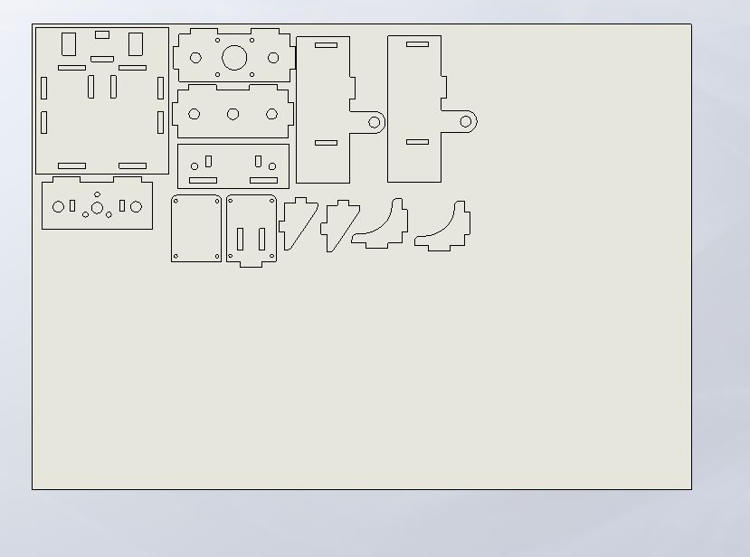
Then I drew the 2d drawing in solidworks an save it as an dxf file to laser cut it.
3.1 Laser cut
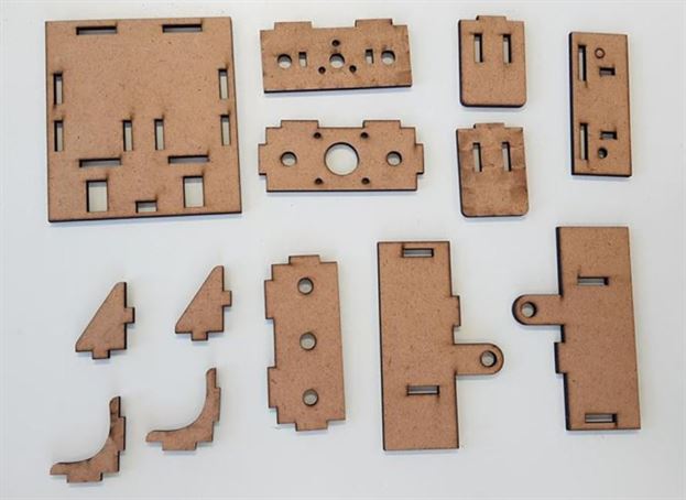
4. Assembly
4.1 Part list
4.2 Hammer
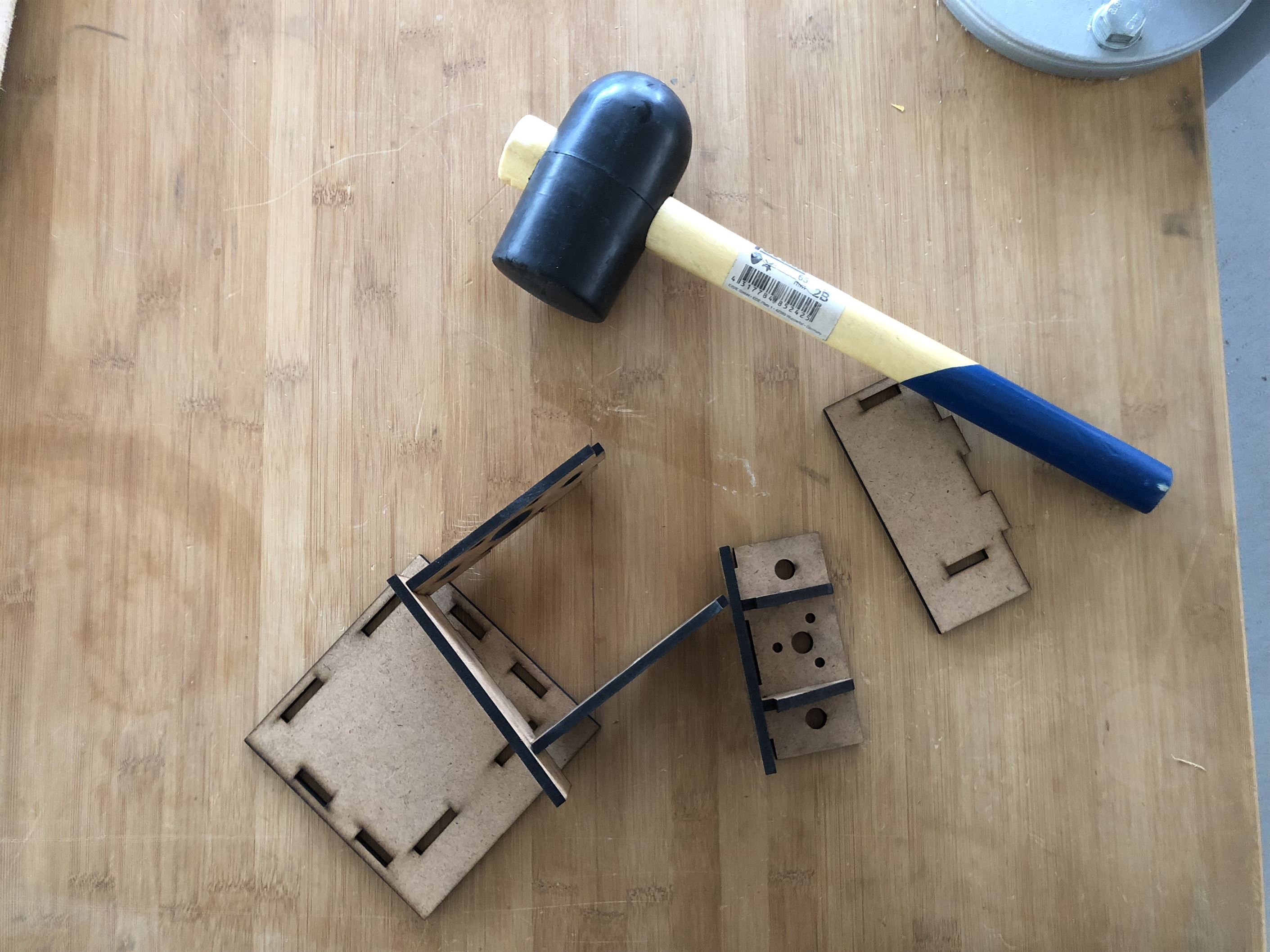
In the assembly, you will need a hammer because I made it a press fit.
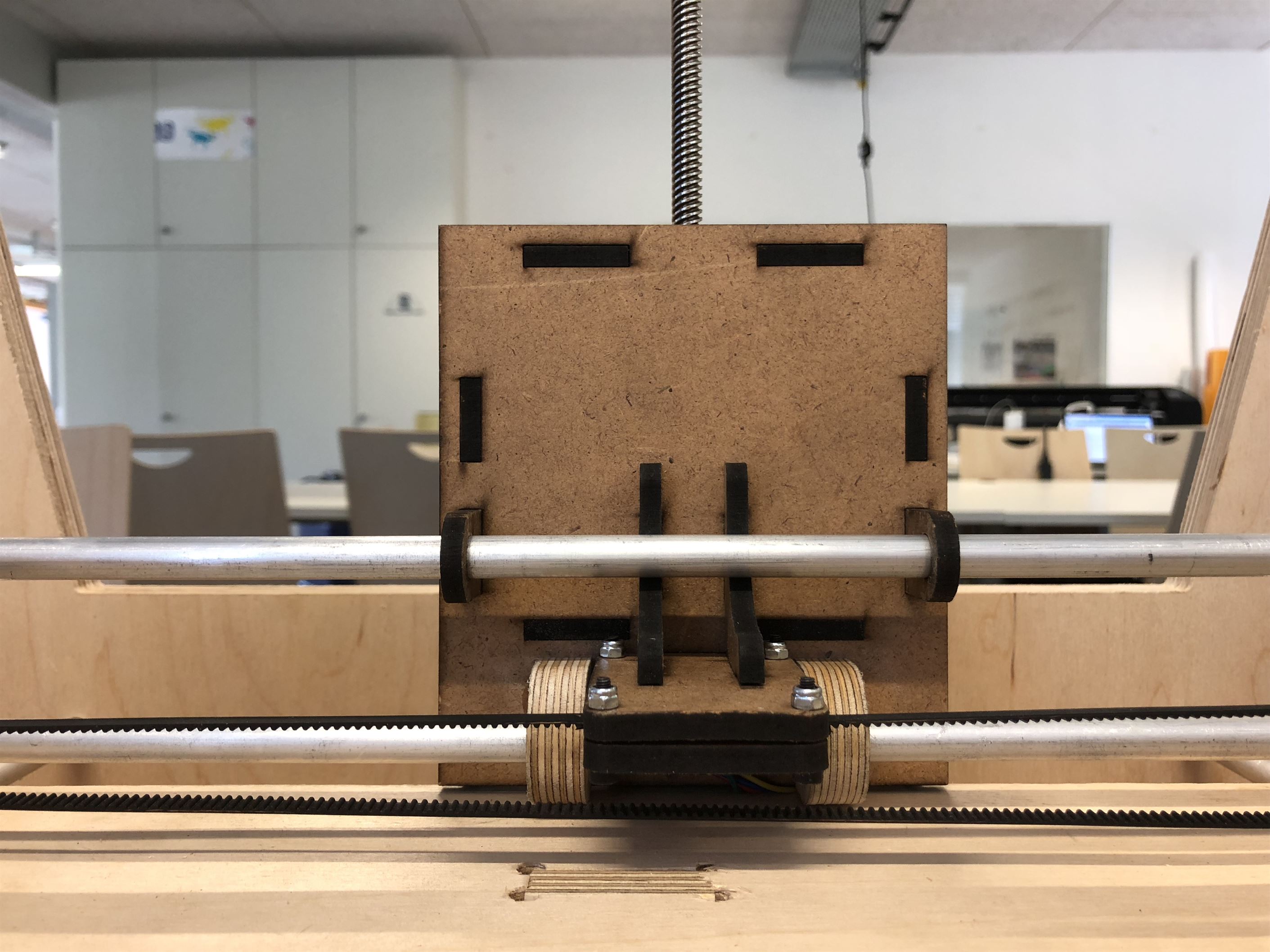
After that I assembled the z-axis to the y direction platoform. I had to squezed the belt between two plate and tide it with the four of the nuts and screw
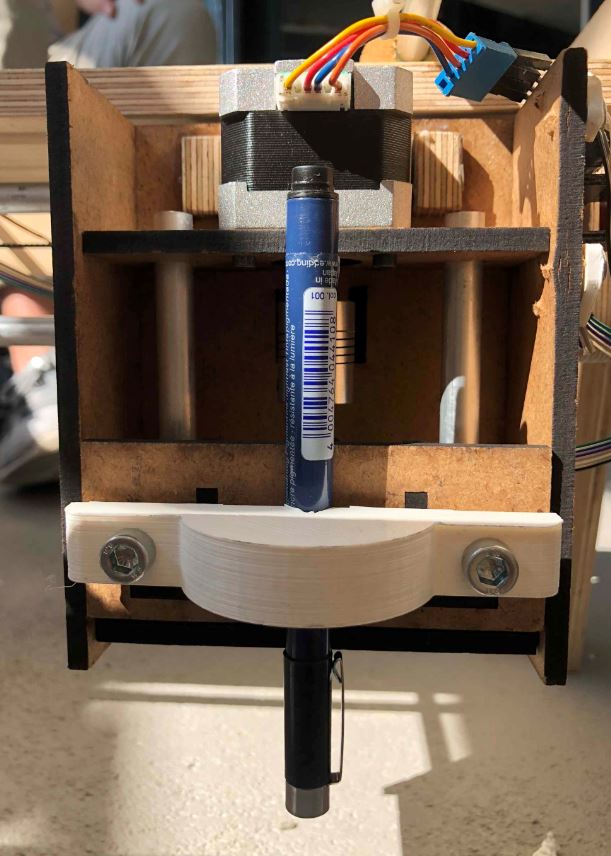
Another part is 3d printed to attach a pen to the end effector.
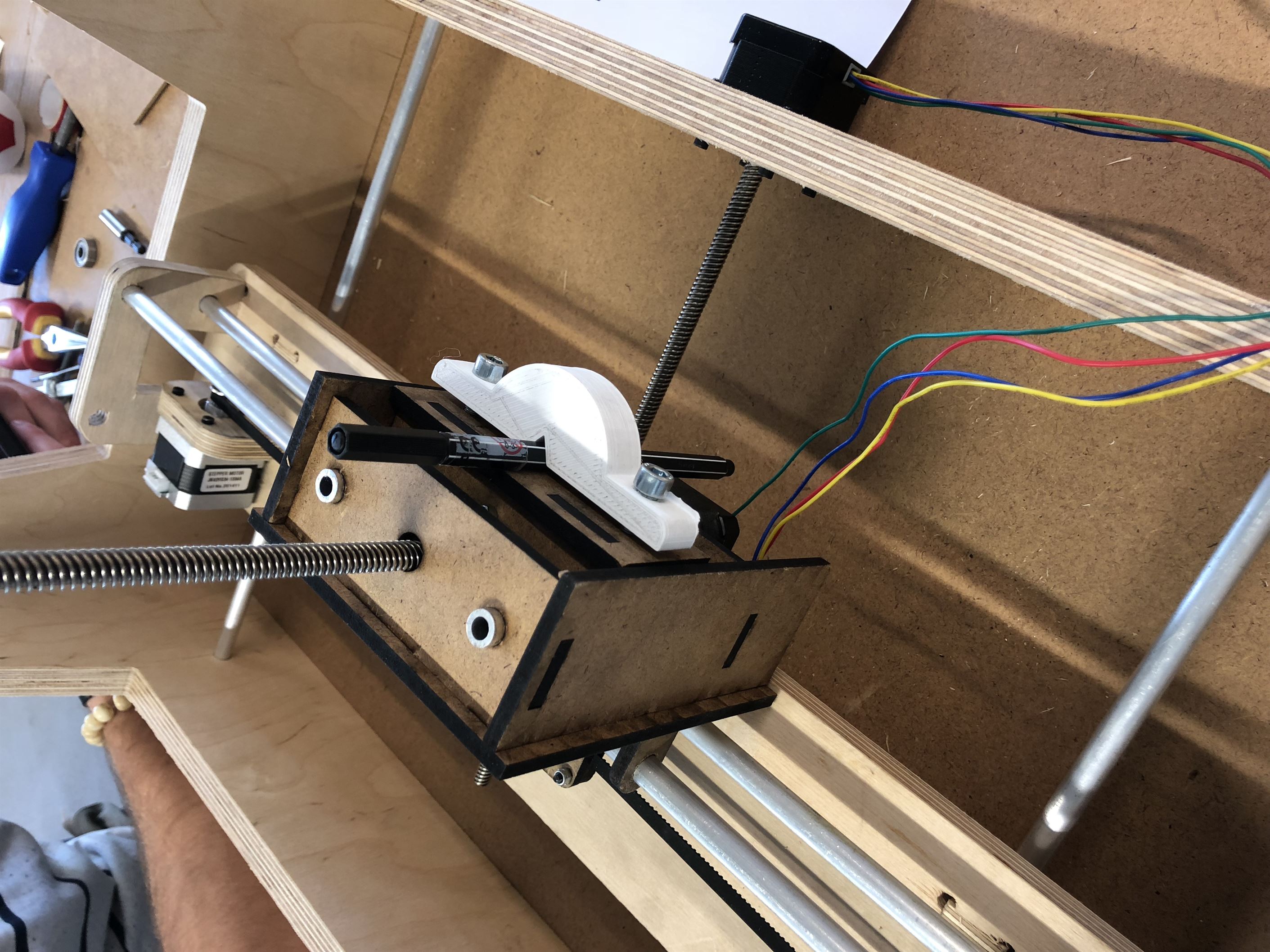
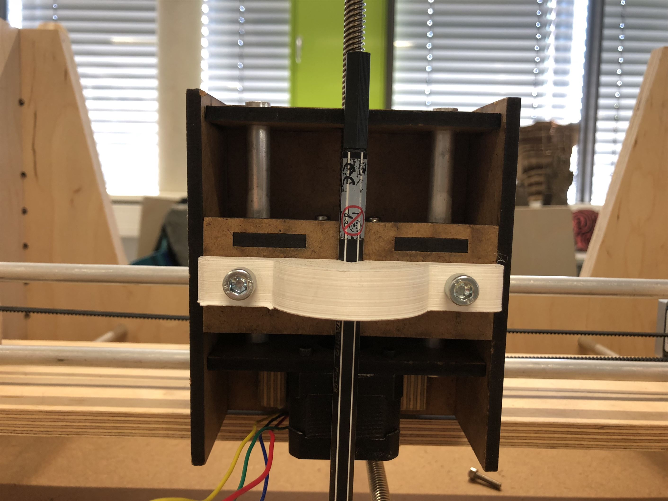
Finally, I can attach them together to the whole machine.
5. Result
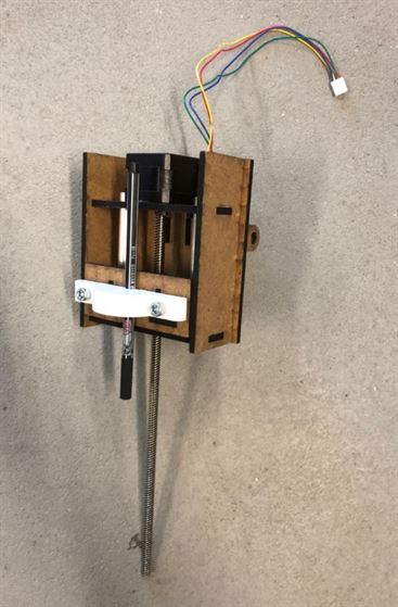
The z-axis platform has finished!
5.1 Testing
Before automate them with motors, it is good to move and check it with hand manually.
6. Reference:
Group documentation by Christian, Emir and Cello
y-axis documentation by Christian
x-axis documentation by Emir