What are the options?
There are multiple ways for the paddles to position themselves correctly to hit the ball.
Camera vision
The first solution that comes into mind is to use camera vision to see where the ball is on the field.
That would mean you’d have a camera above the board, analysing the position of the ball. We found this method to be a bit overkill as you’d need to have quite a powerful device to do the calculations, at least a Raspberry pi, and it wouldn’t be visually pleasing. It would be nice to have a sleek looking standalone machine.
Capacitance
We then thought of having lines of conductive material across the board, and use capacitance to detect when the ball crosses over a line. We did some tests but discovered that the metal ball we were using wasn’t detected with the Touch pins of the ESP-32. We realised that capacitance works when an object has the capacity to absorb or emit energy. A metal ball rolling around doesn’t have that capacity.
There’s a lot of not very conclusive documentation here.
Creating shorts
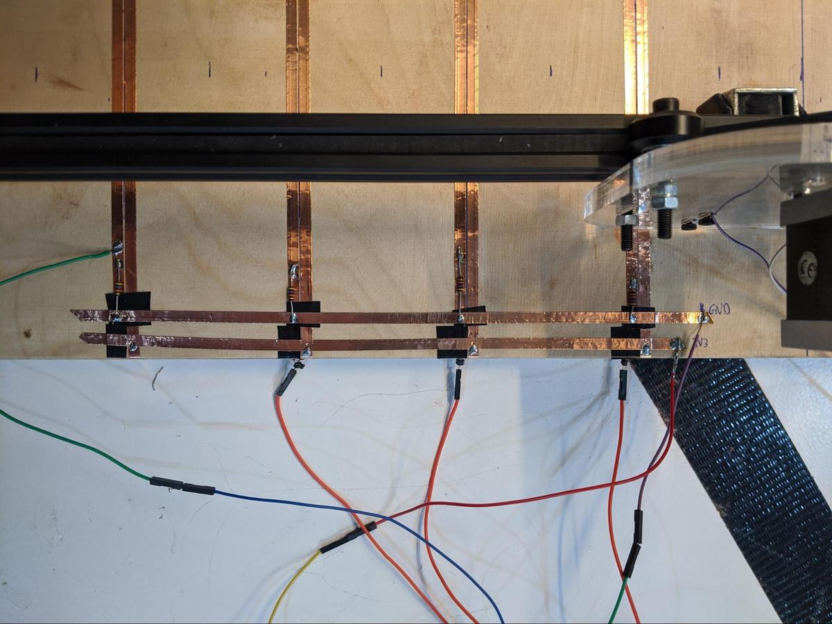
We then thought that if we had two thin lines of conductive material, then when the metal ball rolls over them it would create a short that would be detectable. For this an Arduino would be enough as it’s just a matter of detecting voltage. We did some tests and we could easily detect the passage of the ball, even at hight speed. Good.
Creating shorts
Simple code to detect when the ball crosses to another column. Here’s the code we used.
#define inputPin 22

void setup() {
  Serial.begin(115200);
  delay(1000);
  pinMode(inputPin, INPUT);
}

void loop() {
  const int value = digitalRead(inputPin);
  Serial.println(value);
  delay(20);
}
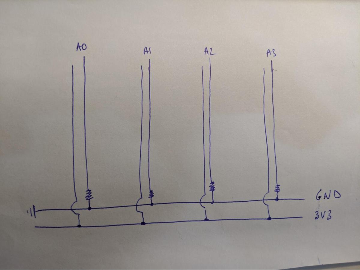
Basically it reads the digital reading of the pin. Thanks to a pull-down resistor it is always 0 (LOW), unless the current goes through, which means it is 1 (HIGH).
How many columns can we have?
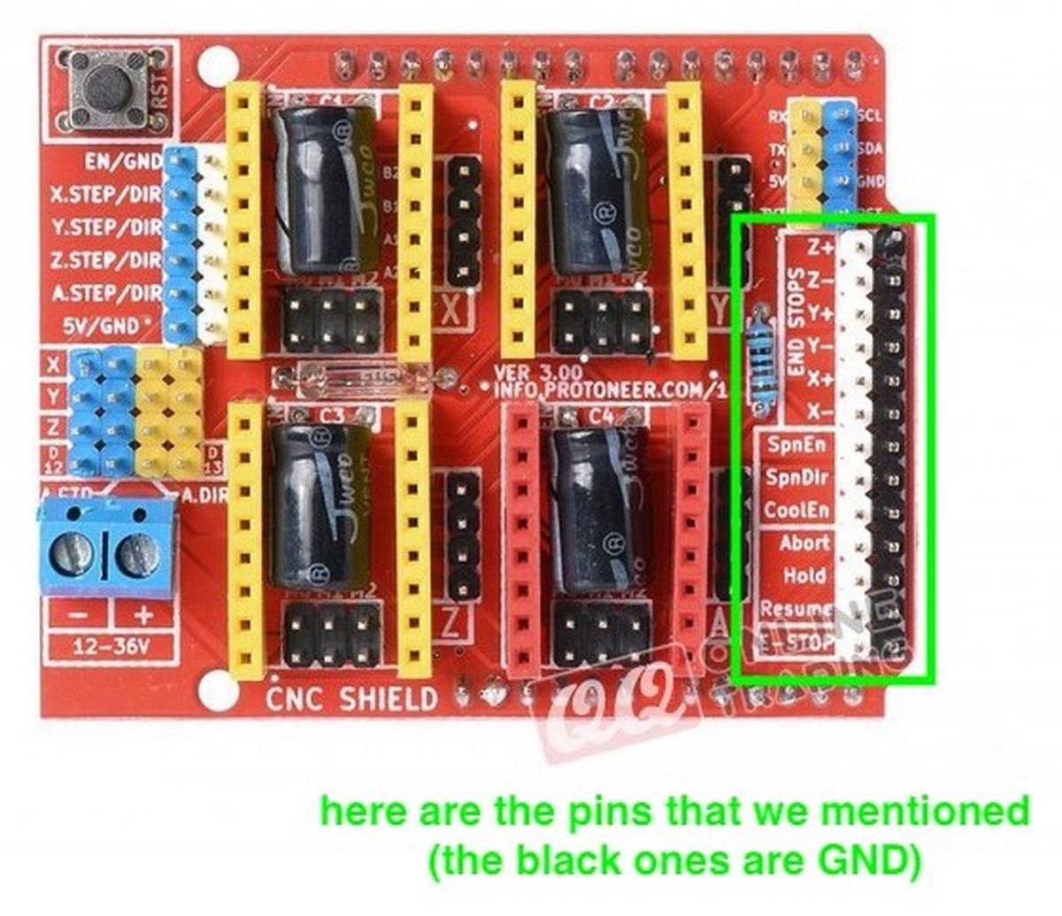
The Arduino Shield to control the NEMA connects to all the pins of the Arduino, but not all pins are being used.
View -> CNC Shield V3 for Arduino UNO - Stepper Motor Controller
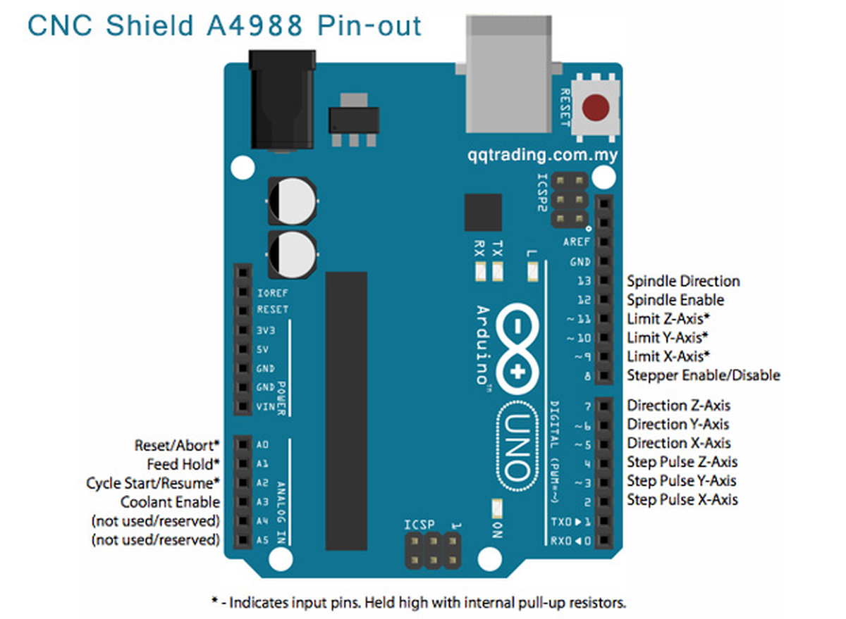
For controlling the two axises we’ll use the pins Direction Y-Axis, Direction X-Axis, Step Pulse Y-Axis & Step pulse X-Axis, in other words (or numbers), we’ll use pin 6, 5, 3 and 2.
We’ll also use Limit X-Axis and Y-Axis, so pin 9 and 10.
We won’t use a spindle, so pins 13 and 12 are free. We won’t use the Z-axis so pin 11 and 4 are also free. We won’t use Reset/Abort, Feed Hold, Cycle Start/Resume and Coolant Enable, so pin A0 to A3. There are two other pins shown as (not used/reserved), pins A4 and A5.
In summary the free pins are:
- 4, 7, 11, 12, 13
- A0, A1, A2, A3, A4 & A5
A total of 11 pins are free. We only need one by line, we are using 4 lines for now.