Firefly Grasshopper Plugin - Bridging hardware and software
FIREFLY is a set of comprehensive software tools dedicated to bridging the gap between Grasshopper - (a free plug-in for Rhino) - the Arduino microcontroller and other input/output devices like web cams, mobile phones, game controllers and more. It allows near real-time data flow between the digital and physical worlds – enabling the possibility to explore virtual and physical prototypes with unprecedented fluidity.
DOWNLOAD EXAMPLE FILES FOR THIS CLASS
For this class we will need this:
- Computer with Windows OSX
- Rhinoceros 5 or 6 + Grasshopper installed
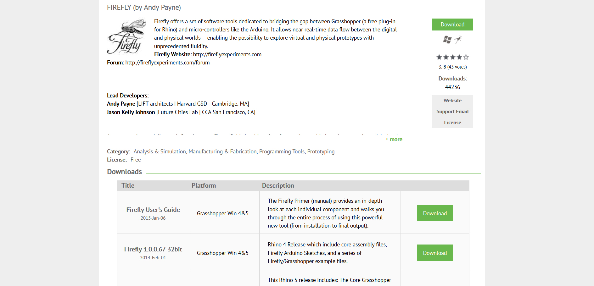
- Firefly Grasshopper Plugin- we recommend version Firefly 1.0.0.69
- Arduino IDE
- Arduino uno board (other compatibles are also okey)+ some analog/digital sensors
YOU CAN DOWNLOAD THE OFFICIAL FIREFLY GUIDE FROM HERE Some examples of what we can do:
Firefly Computer Vision Tools from Andy Payne on Vimeo.
Getting Everything ready (arduino uno firmdata)
We’re going to assume that you’ve already installed the Arduino IDE (this is the software needed to upload programs to the Arduino board)
Step0 - DownloadFirefly
Step1 - Upload the code to the arduino
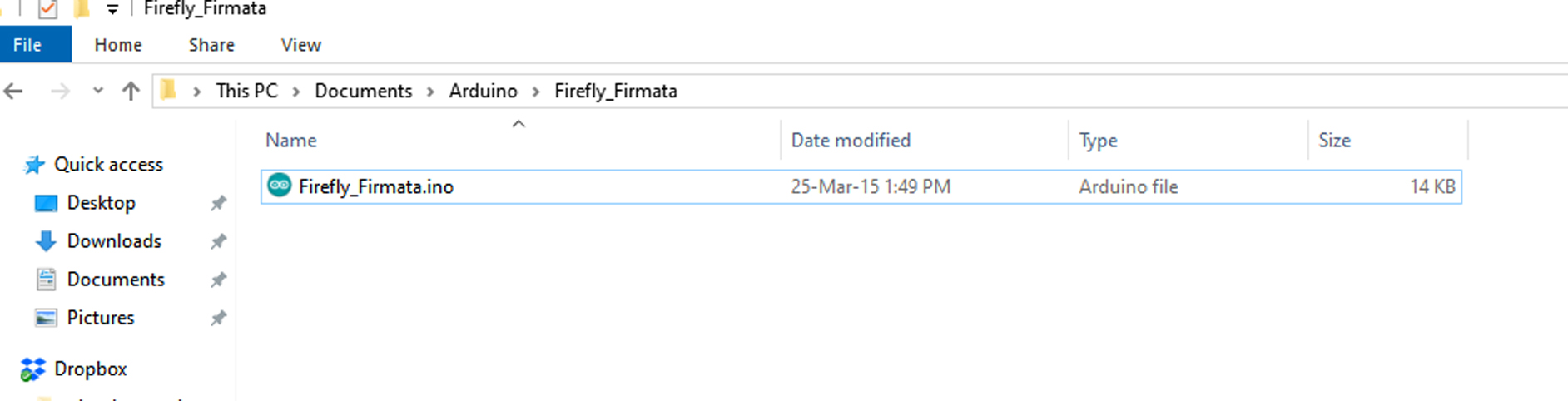
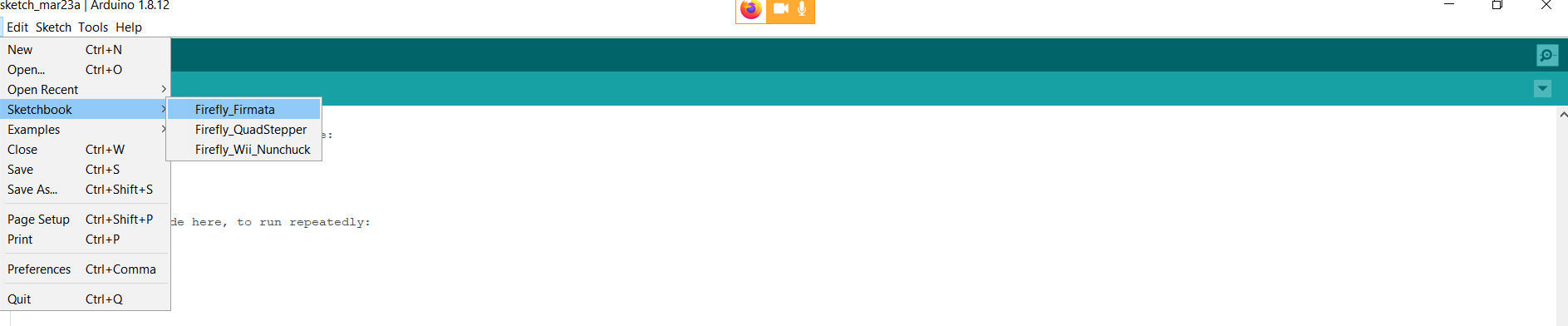
Launch the Arduino IDE application and open the Firefly Firmata sketch: Go to File > Sketchbook > “Firefly_Firmata”.
Now, click on Tools > Boards and make sure you have assigned the appropriate board.
Finally, click on Tools > Serial Port and make sure you have designated the appropriate COM # (these are automatically assigned when you connect your arduino board to your computer).
You’ll want to make a note of the Serial Port number. We will use this again once we get into Grasshopper.
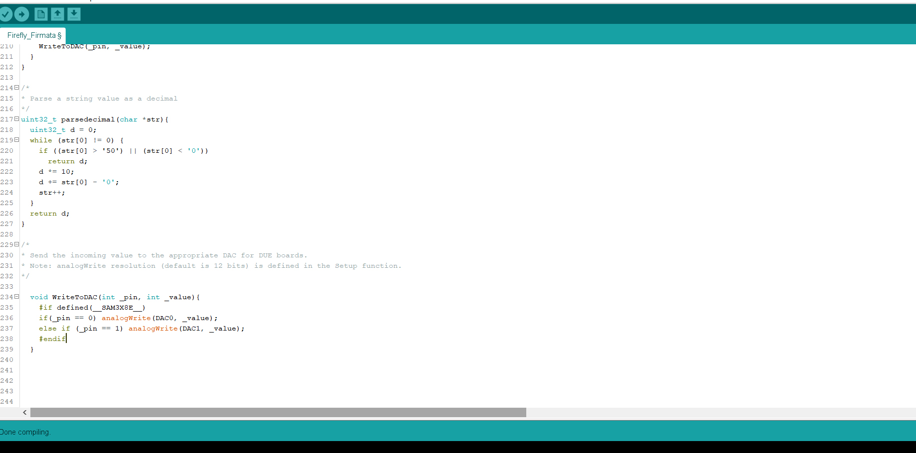
“The code Show an error message while compiling” Some versions of have firefly have an error in the firmdata code here is what you have to change. Go to the last part of the sketch “WriteToDac” is no in the correct location, that part of code should look like:
```
void WriteToDAC(int _pin, int _value){
#if defined(__SAM3X8E__)
if(_pin == 0) analogWrite(DAC0, _value);
else if (_pin == 1) analogWrite(DAC1, _value);
#endif
} ```
You can also download the correct file here
Once you have uploaded the code you should see Done uploading Congratulations! Your Arduino board is now ready to “talk” to Grasshopper.
Step2 - Rhino+Grasshopper+Firefly interfacing
- Open Rhinoceros + Open Grasshopper(type grasshoppe in the rhinoceros command line)
- Go the tab of firefly in grasshopper3d
If everything has been installed correctly you should see this components, that will depend of the version of rhino/firefly you installed.(If you don´t see them all uninstall that version of firefly and try another one)
Firefly – LED on, off & blink example
how to control an LED in Firefly on an Arduino by turning it on/off and making it blink in a pattern. It also shows this process in the Arduino IDE for comparison. The Grasshopper code to turn the LED on/off uses the open port module to start communication and the uno write module for output with a boolean toggle, button, number slider and panel module acting as switches. The blink pattern code uses the binary blink module along with number sliders to control the timing
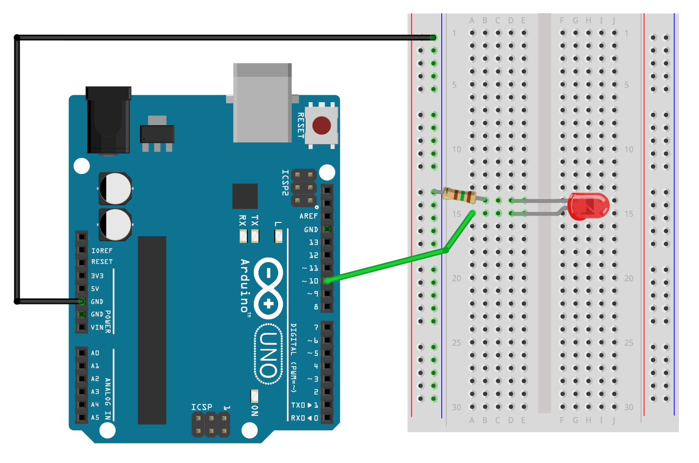 we can use also the on board led of arduino in this case (pin13)
An LED (light emitting diode) requires a resistor inline on either the + or – side to limit the current / brightness. The flat side of the LED rim is the cathode (or the short leg) and connects to negative / ground. The positive voltage gets supplied to the other leg of the LED from the digital output pin of the Arduino. [LED LED(-) → 150Ω → GND, LED(+) → D10]
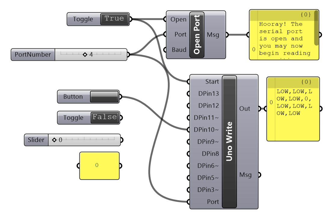
The above example shows us how to blink an led by manually pressing a grasshopper button
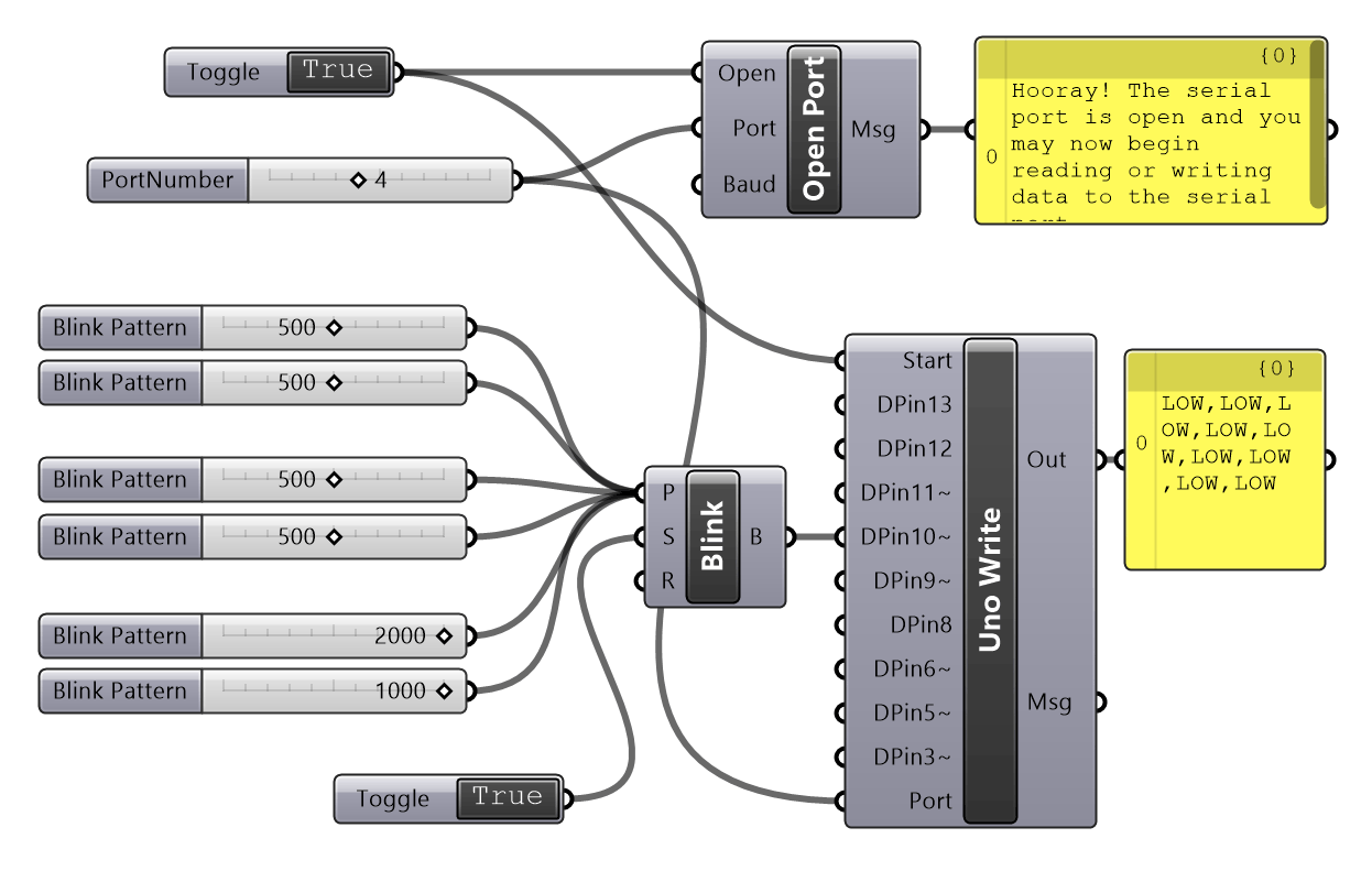
The above example shows us how to blink with a certain controlled delay that is going to be repeated
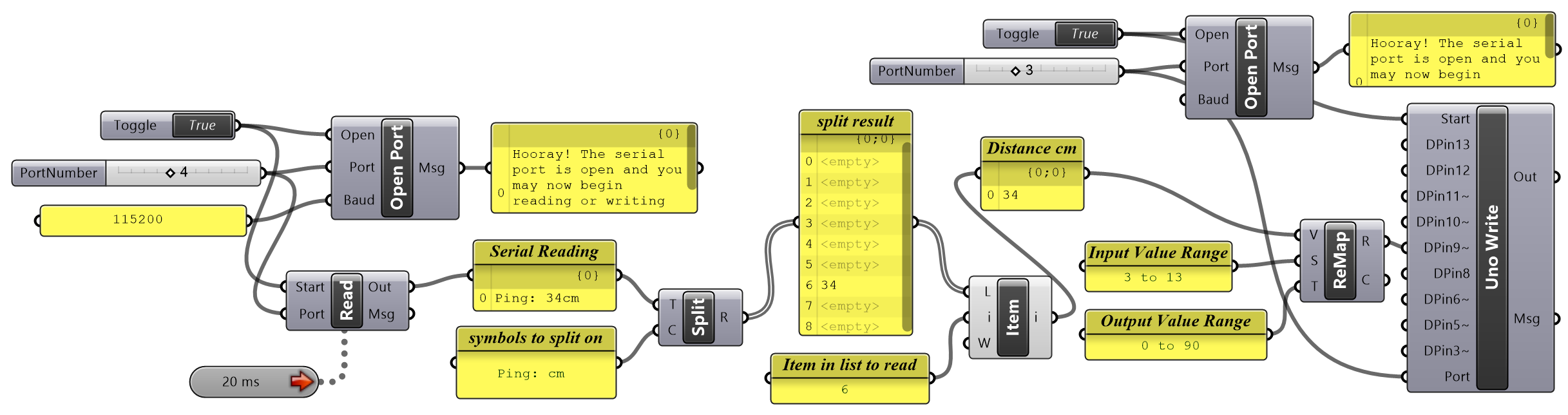
Ultrasonic Firefly Arduino example
Learn how to read serial data in Grasshopper / Firefly from an unsupported sensor connected to an Arduino. In this example an ultrasonic distance sensor (ping sensor) is used, but the same process could be applied to any sensor that requires a library and isn’t supported by Firefly. The values received from the serial read module are first stripped using a text split module to extract only the distance value. This value is then remapped (remap numbers module) to a value suitable for controlling a servo motor which is connected to a second Arduino through Firefly. [Note: Change the video quality to 1080p if you are having difficulty making out details]
This is how you can wire the circuit
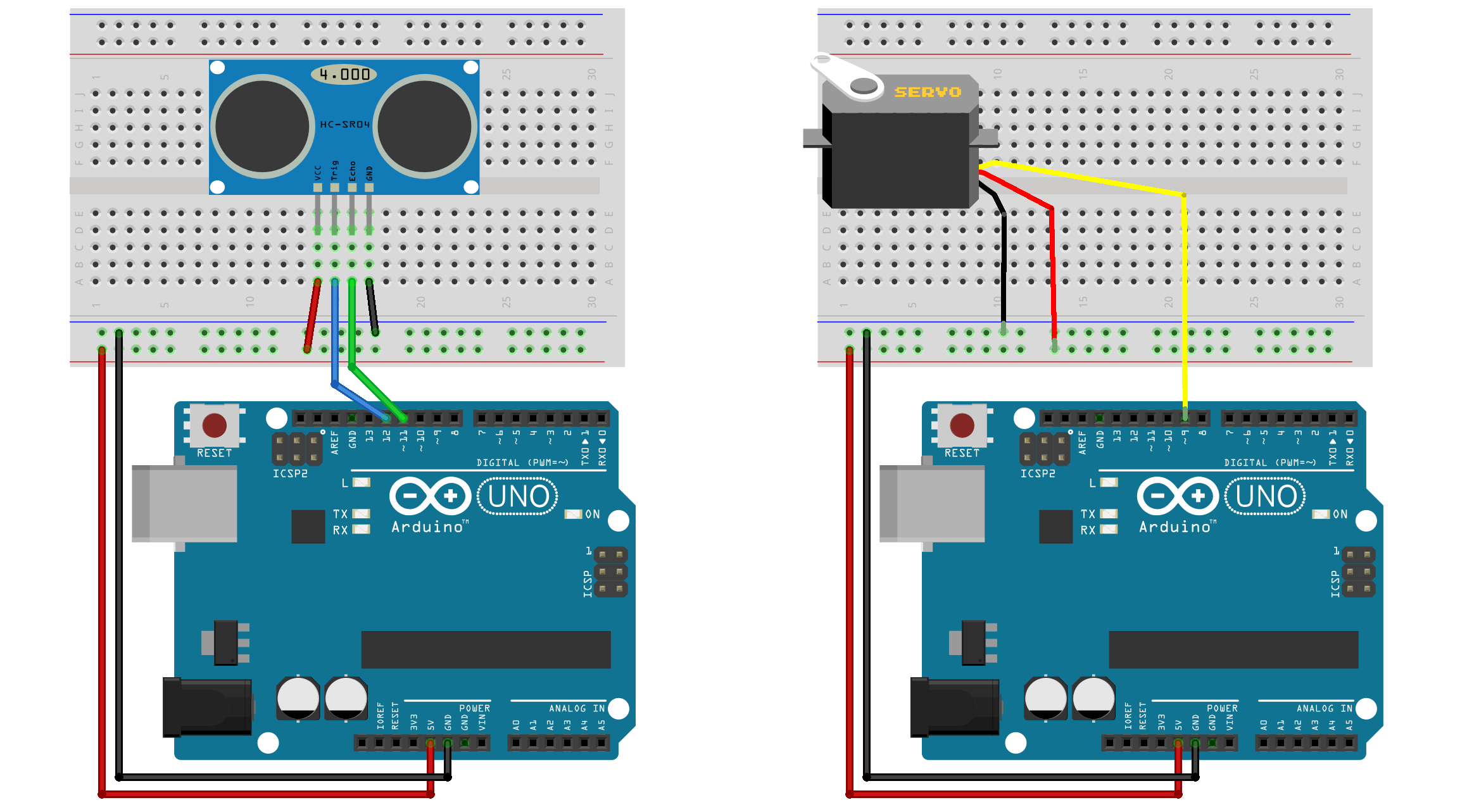
Ultrasonic sensor HC-SR04 – this sensor uses 2 data pins, a trigger pin to send a ‘ping’ and an echo pin to listen for it’s return reflection (note: these sensors can also work with one data pin by linking the trigger and echo pin and using different code). [Connect Vcc → 5V, Gnd → GND, Trig → D12, Echo → D11] Servo motor SG90 9g – servos have 3 wires, 2 for power and a single data pin. Note: the output pin on the Uno Write module needs to be set to ‘servo’. [Servo Red → 5V, Brown → GND, Orange → D9]