Input devices
This documentation is always evolving
Find documentation here
Core ideas
- Why we need sensors.
- Physical, chemical or bio reactions.
- Sensing the environment.
- Close loop systems.
- Inferring metrics.
- Bike speed from counting wheel turns
- Water tank distance from distance from above
- Composed sensors
- Radar: emitter (output) and receiver (input) working in sync
- Complex post processing: Computer vision
- From a list of colors (pixel matrix) to meaningful data (i.e. object location based in color tracking)
Open the discussion with Sensor fusion good and bad potential.
Digital signals
An advanced Mouse detector based on simple digital signal

In the Arduino world to read a digital signal we use the function digitalRead this signal only has two possible values:
| 0 volts | 5 volts |
|---|---|
| HIGH | LOW |
| true | false |
Depending on the type (and age) of the electronics we use the HIGH value corresponds to different voltages, for exmple: 5v, 3.3v, 1.8v.
Pullups y pulldowns
Arduino (Atmega) pins default to inputs, so they don’t need to be explicitly declared as inputs with pinMode() when you’re using them as inputs. Pins configured this way are said to be in a high-impedance state. Input pins make extremely small demands on the circuit that they are sampling, equivalent to a series resistor of 100 megohm in front of the pin. This means that it takes very little current to move the input pin from one state to another.
This also means however, that pins configured as pinMode(pin, INPUT) with nothing connected to them, or with wires connected to them that are not connected to other circuits, will report seemingly random changes in pin state, picking up electrical noise from the environment, or capacitively coupling the state of a nearby pin.
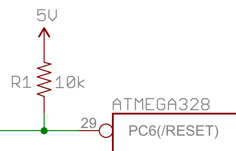
Arduino pins can also be configured as INPUT_PULLUPS, this will activate an internal pullup resistor of 20k. Or you can install external pullups/pulldowns depending if your circuit is active LOW or active HIGH.
Counting pulses
Sometimes we want to count the number of times something happens in a period of time, like for example how many turns does an anemometer every minute. Counting pulses we can measure things like the speed of a bike, the position of a CNC router, the amount of people that enters a building, etc.
pulseIn
The example prints the time duration of a pulse on pin 7.
int pin = 7;
unsigned long duration;

void setup() {
  Serial.begin(9600);
  pinMode(pin, INPUT);
}

void loop() {
  duration = pulseIn(pin, HIGH);
  Serial.println(duration);
}
Debouncing buttons.


/*
  Debounce

  Each time the input pin goes from LOW to HIGH (e.g. because of a push-button
  press), the output pin is toggled from LOW to HIGH or HIGH to LOW. There's a
  minimum delay between toggles to debounce the circuit (i.e. to ignore noise).

  The circuit:
  - LED attached from pin 13 to ground
  - pushbutton attached from pin 2 to +5V
  - 10 kilohm resistor attached from pin 2 to ground

  - Note: On most Arduino boards, there is already an LED on the board connected
    to pin 13, so you don't need any extra components for this example.

  created 21 Nov 2006
  by David A. Mellis
  modified 30 Aug 2011
  by Limor Fried
  modified 28 Dec 2012
  by Mike Walters
  modified 30 Aug 2016
  by Arturo Guadalupi

  This example code is in the public domain.

  http://www.arduino.cc/en/Tutorial/Debounce
*/

// constants won't change. They're used here to set pin numbers:
const int buttonPin = 2;    // the number of the pushbutton pin
const int ledPin = 13;      // the number of the LED pin

// Variables will change:
int ledState = HIGH;         // the current state of the output pin
int buttonState;             // the current reading from the input pin
int lastButtonState = LOW;   // the previous reading from the input pin

// the following variables are unsigned longs because the time, measured in
// milliseconds, will quickly become a bigger number than can be stored in an int.
unsigned long lastDebounceTime = 0;  // the last time the output pin was toggled
unsigned long debounceDelay = 50;    // the debounce time; increase if the output flickers

void setup() {
  pinMode(buttonPin, INPUT);
  pinMode(ledPin, OUTPUT);

  // set initial LED state
  digitalWrite(ledPin, ledState);
}

void loop() {
  // read the state of the switch into a local variable:
  int reading = digitalRead(buttonPin);

  // check to see if you just pressed the button
  // (i.e. the input went from LOW to HIGH), and you've waited long enough
  // since the last press to ignore any noise:

  // If the switch changed, due to noise or pressing:
  if (reading != lastButtonState) {
    // reset the debouncing timer
    lastDebounceTime = millis();
  }

  if ((millis() - lastDebounceTime) > debounceDelay) {
    // whatever the reading is at, it's been there for longer than the debounce
    // delay, so take it as the actual current state:

    // if the button state has changed:
    if (reading != buttonState) {
      buttonState = reading;

      // only toggle the LED if the new button state is HIGH
      if (buttonState == HIGH) {
        ledState = !ledState;
      }
    }
  }

  // set the LED:
  digitalWrite(ledPin, ledState);

  // save the reading. Next time through the loop, it'll be the lastButtonState:
  lastButtonState = reading;
}
Analog values
ADC Analog to Digital converter.
In an ADC circuit there are several steps to go from an analog signal to a digital value. The first stage is called Sampling and Holding:
An analog signal continuously changes with time, in order to measure the signal we have to keep it steady for a short duration so that it can be sampled.
The next stage is Quantizing and Encoding:
On the output of (S/H), a certain voltage level is present. We assign a numerical value to it. The nearest value, in correspondence with the amplitude of sampling and holding signal, is searched.

The resolution of an ADC is measured in bits, a one bit resolution ADC is capable of delivering 2¹ different values (0 and 1). The Arduino UNO has a 10 bit integrated ADC that means it can deliver 2¹⁰ values from 0 to 1023.
Voltage divider
How to measure the resistance of a variable resistor

R1 is variable but R2 is static and defined by us (we try to find a resistor that is similar to the expected middle point value of the sensor readings).
To solve for R1:
To solve for R2:


From Wikipedia
int R2 = 10000;
float VIN = 5.0;

void setup() {
  Serial.begin(9600);
}

void loop() {

  // read the input on analog pin 0:
  int sensorValue = analogRead(A0);

  // Convert the analog reading (which goes from 0 - 1023) to a voltage (0 - 5V):
  float voltage = sensorValue * (5.0 / 1023.0);

  // Get the value of R1
  int ldr = ((R2 * VIN) / voltage) - R2;

  // print out the value you read:
  Serial.print("voltage: ");
  Serial.println(voltage);
  Serial.print("LDR value: ");
  Serial.println(ldr);
}
How to choose and use a sensor
The section is aimed at INPUTS (sensors) but many concepts work also for OUTPUTS (motors, LEDs)
- How to choose sensor?
- Integrated circuits, breakout boards, and off-the-shelf devices
- IC Component
- Adafruit IMU Breakout
- Wii Nunchuck (check in Wallapop, Cash converters, Ebay…)
- Integrated circuits, breakout boards, and off-the-shelf devices
- How to wire a sensor?
- We will always look for well documented sensors learn.sparkfun.com, learn.adafruit.com
- Download the EAGLES from the Breakout boards to help you, example
- How to code for a sensor?
- Fab Academy sensors
- Sensor interfaces:
- Tell me soDigital Communication: Serial / UART, SPI, I2C :warning: We will always use an specific sensor library implementing the comunication
Sensor list
We have a Sensor list that need some work and updates, but still works as reference.