Final Project
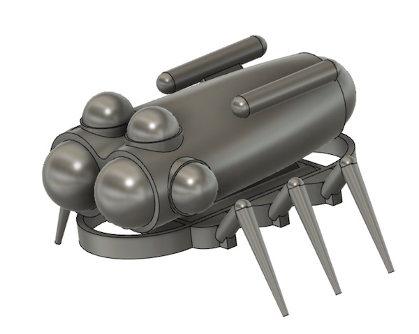
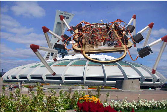
There’s a machine I’d like to build. I applied for a huge EU grant with five other university and industrial partners, but unfortunately we didn’t get the money. Here’s the beast:

The full-size machine was meant to be big enough to carry two people on a multiple-day mission at depths up to about 20m. As designed it would have weighed 7 tonnes. The concept is that it should walk on six legs and use its remaining two to carry pincers or other tools.
The unique thing about this machine was that it was to have been equipped with a set of artificial gills. In the cartoon above, the gills are represented by the belt of cylinders around the trailing end of the hull. These were developed by some colleagues in London. The concept was that they would provide the top-up supply for a rebreather system on board.
The legs and pincers were to be hydraulically driven, and the machine would have had lithium battery power. There would have been a set of biomimetic tools, including a custom-built version of Festo’s fin-ray claw and cameleon-inspired soft gripper, with a tool-changing device for the two forward legs. Under the belly of the machine there was meant to be a biomimetic microplastic harvester based on the feeding current generated by the legs of a mysid shrimp.


FabAcademy Objective
The full-size machine was obviously well beyond the scope of a FabAcademy project, but I wanted to take a first step in that direction by building a 1:15 scale model version of the machine as a testing platform for the leg kinematics and responsive dynamics that the eventual full size machine will eventually need to deal with a real world.
Design Philosphy
I followed the engineering design philosophy as defined by the German VDI, which sets out the stages of the design process thus:

There’s a lot going on in this figure. The main flow is in the “Stages” column, where the task is broken up into an ordered set of steps which build on each other as the design progresses from problem to prototype. The results column shows the concrete deliverables from the process: these get more detailed as they progress from a single initial specification to the final prototype with multiple component modules. The two vertical boxes are really important elements of the figure. The left hand box reminds the designer that the progression is not necessary all in a single direction; it may often be necessary to back up one or more steps, and it may sometimes be possible to move quickly forward. The right hand box highlights that the requirements that led to the specification will invariably change over the course of the development as the solution becomes clearer.
This process is applied to the system as a whole, and then to each of the subsystems (“modules” in the figure) in turn. In my case, this meant starting with the overall biomimetic design of the six-legged robot, and then focussing in on the mechanics and electronics of the legs, sensors and control software that combined to make it move. Not all steps in the design process will necessarily appear in each of the modules.
Overall Design
Time to start designing the little beast.
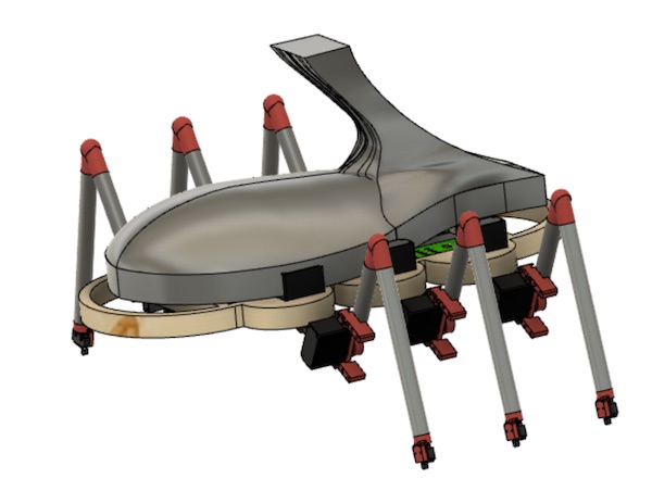
Here is a Fusion360 model of the little dreamboat:
You’ll remember this is the little model I 3D printed for the week 6 assignment. The goal of my final project is to build the chassis part and work out how to coordinate the movement of the six legs.
This report follows the traditional design process and addresses each of the steps of that process in turn. For a diary-style report on the learning I did during this part of the FabAcademy, please see the Project Diary.
Biomimetic Inspiration
Mobile robotics is usually based on wheeled or tracked vehicles. These however often have limited mobility in complex topographies, and they often leave quite significant tracks which disrupt the environments they operate in. An alternative design is offered by nature’s best robots, otherwise known as animals, which for the most part walk on various numbers of discrete legs. (There are some slithering and rolling animals, but they have other challenges of their own.)
Terrestrial vertebrates are limited to a single body bauplan with only four legs. Evolutionarily they all derive from the same lobe-finned fish that crawled out of a lake in equatorial Laurentia some 375 hundred million years ago. The world would be a different place if the original lungfish had had six fins rather than the four it bequeathed its descendent Tiktaalik.

One of the big challenges that faced those early beasts, and indeed that still challenges modern vertebrates, is how to walk stably on four legs. It is possible, by applying some significant torque and shifting the centre of gravity around, to arrange a kind of stability for slow locomotion, but that results in a snake- or fish-like backbone bending that doesn’t lend itself well to the engineering of a cabin or hull to transport people or freight.
Invertebrates, by contrast, are not so evolutionarily limited. Pretty much every imaginable number of legs appears on an invertebrate body somewhere. They’re not even constrained to even numbers of legs, as I showed with the starfish in assignment 17. However most of the highly mobile invertebrates do display bilateral symmetry and therefore an even number of legs.
In this case, the inspiration for the robot is taken from any of the crabs, typified by the blue land crab Cardisoma guanhumi below.

Decapod crustaceans such as crabs and lobsters typically walk on eight legs while carrying around two additional highly modified claws, holding them off the ground while they walk. In the design here, I’ve simplified the situation by removing the claws and the fourth pair of legs, and have ended up with a hybrid bioinspiration that looks arguably more like a ladybird.

Six-legged insects like the ladybird or the better-studied cockroach walk in a locomotor pattern known as the alternating tripod gait. They stand on three legs (two on one side and one on the other), and move the other three simultaneously before repeating the motion for the other tripod. The motion can be seen in the video below.
This is an incredibly stable gait, as jokingly evidenced by how much more difficult it is to tip a cockroach than a cow.
(BTW - cow-tipping isn’t a thing.)
Overall Specification
Thoughts about size. The beast was to be about 30cm long and the core of it was expected to weigh something like 1kg. That was enough to start thinking about torques and strengths. I’d also decided to limit myself to materials I could work with easily in the lab and stuff I could buy easily at the local hardware store. The final robot was therefore not expected to look exactly like the CAD presented above, but my goal was to try to keep as close to it as I could.
The electronics underlying the design needed to be sufficient to control the motion of the legs, which were to be driven by an as yet unspecified actuation system. The intent was to make use of the skills acquired in FabAcademy, so I limited my choice of microcontrollers to the ones I’d already been introduced to. The goal was to keep things simple.
One assignment requirement was that the machine must have sensory feedback of some kind. Two priorities immediately lept out, namely forward (avoiding bumping into things) and down (feeling the ground).
The software architecture had to be designed so that it can be deployed quickly and easily to all of the programmable parts of the robot. This could have meant a completely centralised system or a more distributed one, with a central pattern generator doing the overall control and each leg’s microcontroller looking after the local control of the leg segment.
Formalising these requirements into a table following the template by Pahl & Beitz produces the full specification, or requirements list, which can be viewed in the following file.
Solution Principles
The next step in the design process was to think of the objective as a system with multiple parts. The model I was looking to make was not as complex a machine as, say, an injection moulder for industrial production, but I did still have to go through the same steps to develop it, though of course many were be either self-evident or quickly dealt with.
Since the decision was made to go with legged locomotion, and to go with six legs, then the rest of the design requirements fell relatively quickly into place. The system broke down into the following components, each of which needed to be developed according to the full design process.
- Legs
- Shoulder ab/ad-duction
- Shoulder internal/external rotation
- Elbow flexion/extension
- Touch sensor
- Chassis
- Space for components
- Structure for leg attachment
- Style!
- Electronics
- Leg PCB design
- Central controller PCB
- Backbone and programming PCB
- Power
- Source
- Distribution
- Software Architecture
- Modular structure (leg control)
- Communications
- External sensors
- Gait Patterns
- Stepping one leg at a time
- Alternating tripod gait
With those subsystems in mind, I could work through each following the accepted steps of design. I made one departure from the VDI approach, in that I left out the function structures - once I’d broken the overall design into the subsystems, the function structures (diagrams with signal, material and force flows) were honestly superfluous to solving the challenge.
At this stage in the design, the process focuses on the options that are available to accomplish the various tasks in the specification. One can use a design tree or a morphological box to explore the options. I used this brainstorming process to list out the various ways solutions could be achieved to various elements of the specified problem.
| Function | Options | ||||
|---|---|---|---|---|---|
| Legs | |||||
| Number | 4 | 6 | 8 | 10 | |
| Joints | 1 | 2 | 3 | 4 | |
| Actuation | Servos | Steppers | Pneumatics | Hydraulics | Artificial Muscles |
| Chassis | |||||
| Material | Wood | Plastic | Metal | ||
| Components | Single | 1+Legs | Multiple | ||
| Electronics | |||||
| Boards | Single | Modular | |||
| Driver | Arduino | AtTiny | Raspberry Pi | ||
| Sensing | |||||
| Forward | Sonar | Lidar | Microswitch | ||
| Ground | Pressure pads | Microswitch | Capacitative | Strain Sensor | |
| Control | |||||
| Architecture | Centralised | Distributed * | |||
| Communications | Serial | I2C | |||
| Power | |||||
| Location | Onboard | External | |||
| Distribution | All in one * | Parallel |
The options in bold are the ones I settled on in the end. The starred ones are options I tried at first, then abandonned in subsequent design iterations as unforeseen challenges made themselves obvious.
System of Modules
The six-legged robot lent itself nicely to a modular design. The legs were all identical in their mechanical and electrical design. Once the legs were specified and designed, I could set the final dimensions of the chassis. The electronics followed that, and finally the programming rounded out the prototype.
Legs
Specification
The role of the legs was to support the weight of the robot both in standing and in motion. They also needed to transmit the rotational torques to the body of the robot to translate it forward or back (other directions will follow later). The overall weight of the robot was specified at under 2kg, so by designing the legs to take 1kg each, I felt I had included enough of a safety factor to ensure solid mechanical support.
Solution Principle
Inspired by the crab or insect leg design, I opted for a three-segment leg with an elbow and a wrist distal to a shoulder at the chassis. The leg dimensions were selected to give the robotic beast a shape similar to the crab I mentioned earlier. The motivation is firstly esthetically pleasant, and secondly the geometries that Nature adopts are generally mechanically well founded.
The original cartoon design looked like this.
Module Structures
With a principle design set, I could start on the details of the elements involved in the overall leg design. The following table shows the design challenges.
| Leg Element | Role | Material | Processing | Challenges |
|---|---|---|---|---|
| Shafts | Force, torque transmission | Aluminum | Hacksaw | Bending, rotation |
| Finger | Tactile sensor | CotS | Fastening, orientation, wire routing | |
| Foot | Sensor carrier | PLA | 3D Print | |
| Wrist | Fulcrum for lower leg | PLA | 3D Print | Transmit vertical force |
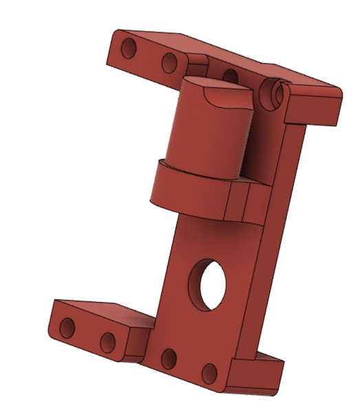
| Elbow | Servo holder, fulcrum for middle leg | PLA | 3D Print | Support two servos and transmit torque |
| Shoulder | Transmit whole leg torque | PLA | 3D Print | Deal with roll/heave torque while allowing sweep movements |
| Scapula | Anchor for leg assembly | MDF * | Milling * | Support roll/heave torque, restrain sweep servo |
| Servos | Actuation | CotS | Torque production & holding |
The choices summarised in the table above are described in the sections that follow. The asterisk indicates a failure in the leg system manufacturing process that led to a redesign of the chassis geometry.
Specifying the Servos
The first real mechanical task was to decide how big the servo motors would need to be to support the weight of the machine. The shape of the legs was deliberate: the idea was to shorten the lever arms but also to load the leg tubes primarily in tension and compression, where they’d be stronger, than in bending, which was what they would have undergone had the legs been straight out to the side.
Originally there were three motors in the design of each leg. For simplicity and redundancy, I wanted to use the same servo motors throughout the machine. This meant that two of the three motors were be somewhat overspecified, but the price tag wasn’t so great that it mattered.
The worst case for loading in this arrangement was the knee or elbow joint, at the top of the picture, where the two long beams meet. The motor had to provide the torque to hold the two beams in any particular orientation. The balance of torques looked like this:
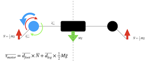
With dimensions dfoot=20cm, dleg=10cm, and M = 1kg, the total torque at the blue joint was 0.5kg x (7.5+15) = 11.5kgcm (weird unit, but it’s what the servo manufacturers seem to use). Because the robot was designed to be supported on at three legs at all times (it would walk with an alternating tripod gait), the load was expected to be some 30% less. The leg was furthermore designed never to go flat, but rather always have a bend at the motor joint, to further reduce the torque. It was therefore sufficient to use a standard analog servo with a stall torque at 5V of 9 kgcm. FeeTech makes a relatively inexpensive motor that met these specs. There didn’t seem to be a standalone datasheet available, but the description is on the web here.
Preliminary Layout
Once the motors had been selected, the CAD could proceed around them and the electronics, which are described in a later sections. The dimensions and materials of the legs were selected based on the specified motors and the loading torques in the legs. Here’s what the CAD looks like:
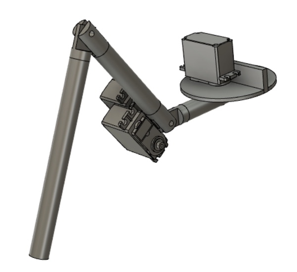
The first motor was fastened to the riser on the disk, which was in turn fastened to the rover’s main chassis frame. The first leg segment (called the femur) rotated around the axis of the motor shaft. I considered placing roller bearings between its top surface and the underside of the disk. The idea there was to carry the weight using structures which aren’t the motor itself. In the end, the off-axis strength of the motor shaft rendered this design complication unnecessary.
The other two motors were to be mounted on the second leg segment (tibia). One of the motors was to drive the angle of the tibia relative to the femur directly through a shaft. There was to be a bearing of some kind around that shaft to take the forces, so that the motor would only have to deal with the torque. The second motor (of this pair, third overall) was also to be mounted at the inboard end of the tibia, with a belt out along the tibia to the “ankle” joint, where it was to actuate a pulley on a shaft to actuate the foot segment. There were two reasons for keeping the third motor inboard: to reduce the outboard weight and to improve the clearance between leg segments when assembled on the main chassis.
Once the geometry was settled and belts/pulleys ordered, the final shape of the knee and hip joints could be drawn up. Space had to be left for the shaft attachments of the servos. The preliminary design looked like this:
It was expected that the final design would have to be revisited once the parts had arrived and exact measurements could be made. It was also expected that a belt tensioner would be required, which would have required further modification of the design.
Definite Layouts
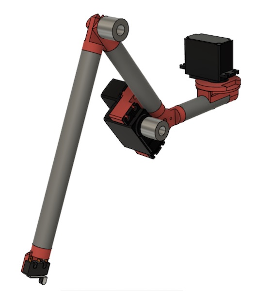
Early prototyping efforts taught me a lot of lessons in the design. There were a lot of unknowns in the material properties of the 3D printed plastic, particularly since I was (and am still) no expert in the process. See the Project Diary for details of the learning process. Here I have presented the final design which grew out of that learning.
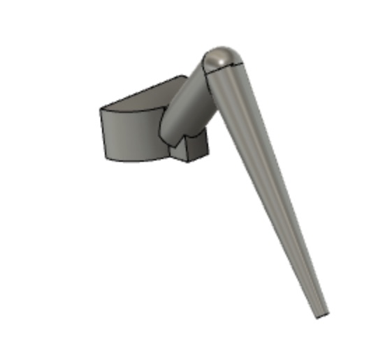
One major simplification was made to the original design and one of the parts was substantially beefed up. The simplification was the reduction from three to two segments and the removal of one motor. The leg now consisted of a short, straight upper arm and a crooked lower arm, the wrist from the earlier design having been replaced with a rigid bend.

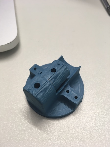
The foot element retained its original shape:

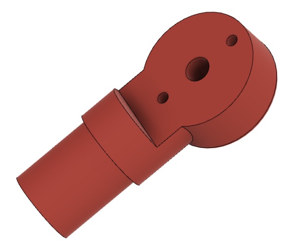
The wrist element was made rigid:

The two parts of the knee were modified only slightly to make better room for the connections to the motor.
The shoulder part was highly modified to compensate for cracking. Extra material was added in several areas to distribute the force more evenly. Holes were designed into the shape to allow for the addition of 3mm bolts to provide more strength parpendicular to the printing plane.

Manufacture
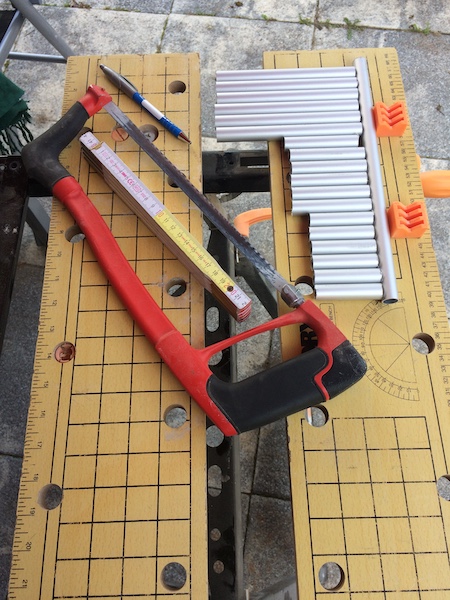
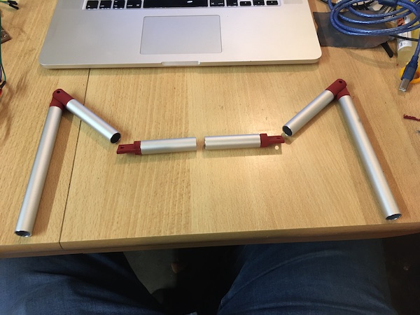
The long elements of the legs were made out of aluminum tubing (13mm inner diameter, 1mm wall thickness), purchased from the local hardware store. Some quick work with a carpenter’s rule, a pen, and a hacksaw produced all of the long tubular parts for the little beast.
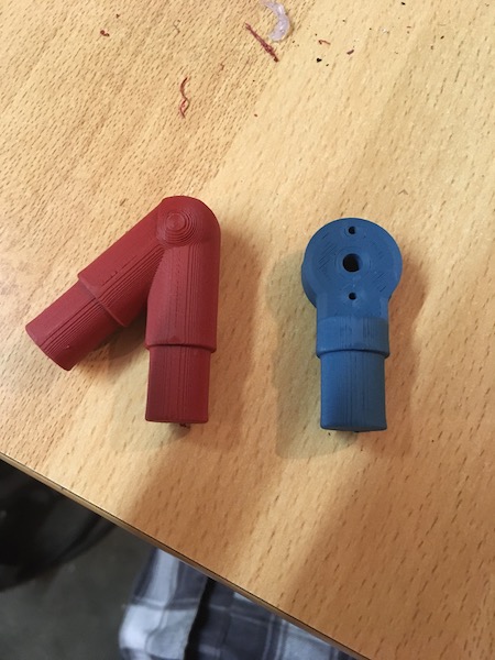
The joints were made on the 3D printer. I increased the fill percentage to 45%, set the parts carefully at a 30° angle to avoid creating shear planes perpendicular to the long axis of the parts, and used the gyroid fill pattern to give the parts a bit more strength. The joint parts are shown below with the aluminum tubes.
The servo motor holders for the legs were next.
For the shoulder parts, where the torques were largest, I increased the wall thickness further. The action of adding the holes to the design for the reinforcing bolts also resulted in an increase in the infill density, further strengthening the part.
The elbow and wrist parts were also revised to make them denser. The wrist part was rotated 90° around its long axis to ensure that the printer put rings around the central axle, which prevented the part from cracking open along a line between the bolt holes.
The final printer settings are listed in the Project Diary
Chassis
Specification
The role of the chassis was to support hold the whole beast together. It had to link the six legs, restrain their shoulder motors, and provide an enclosure for the electronics. Additionally it also had to withstand the torques created by the action of standing on three, five or six legs, depending on the gait and stage of gait. It had to be light enough in weight not to overload the motors. It had to provide some means for the robot to be carried and transported by hand. Finally, it had to be esthetically pleasant in form.
Solution Principle
The chassis wasn’t a philosophically complicated element to design. It consisted essentially of a set of beams arranged in a geometry that retained the electronics package and distributed the legs, while also providing enough strength to take the forces and torques from the legs.
Module Structure
In the first design iteration, the chassis consisted of two modules: a main frame, with forward and aft grab rings. A rail around the inside of the straight sides provided support for the electronics package. The leg assemblies were to be bolted to the sides of the chassis. In the final design of the chassis, the leg supports were integrated into the chassis itself, reducing the module count to just one.
Preliminary Layout
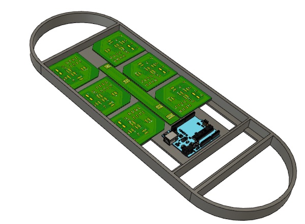
The chassis had to be large enough to spread out the legs and to accommodate the electronics boards that controlled each of the leg units. The boards, and Arduino Uno and a serial bus were assembled into a compact planar arrangement. The chassis was then designed around those, lengthened a bit to spread out the legs for locomotion. A shelf around the inside of the frame was to provide an anchoring point for the circuit boards and strengthens the frame itself.
Definite Layout
In the definitive layout, the leg supports (scapulae) were integrated into the chassis itself.
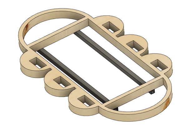
The part was designed for laser cutting - hence the square holes which would not have been possible to machine on the mill.
Manufacture
The frame was cut using the laser cutter in my local advisor’s workshop in Xanten. His very kind offer also solved the manufacture of the frame problem. That came back from the laser cutter beautifully cut. It did feel a little fragile, but the quick addition of two aluminium bars to its underside (which also serve to carry the electronics board - more on that later) made for a sturdy little beast.
Electronics
No robot is complete without an electronic nervous system. My little rover was no exception! The design philosphy was “distributed control” with a biomimetic approach to keep it simple.
Specification
The specification for the electronics system was that it should be able to control 12 servo motors on six legs from a 5V supply and respond to sensory information about its surroundings.
Solution Principle
The overall architecture consisted of a microcontroller-based control board for each of the legs, connected via a serial protocol to a central PCB, with a further microcontroller which coordinated the motion of the legs and adjusted the robot’s behaviour based on sensor readings. Power and signal distribution were accomplished using a custom-made data/power bus.
Module Structure
The modular structure consisted of six identical leg-control boards and one central controller designed around the AtTiny84 microcontroller. Each of the leg modules included cour LEDs for debugging purposes, three servo headers and a signal input header, as well as an ISP header to facilitate programming. The central board was similarly designed, though with less LEDs and connections. A further power and signal distribution board was included as the base of a cable-based power/data bus.
Preliminary Layout
Leg Boards
The original concept (see Week 12)called for three servo motors per leg, but that was simplified to two in the mechanical design phase. A single AtTiny84 on each leg was therefore sufficient to drive the servos with one pin each, read the microswitch on the footpad, and communicate via some kind of simple bus with the CPG. Provision was left for the third servo or eventually for a second sensor. Finally four LEDs were included for debugging purposes.
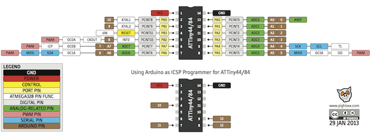
The pinout for the AtTiny84 is shown here:
The wiring diagram for one leg looks like this:
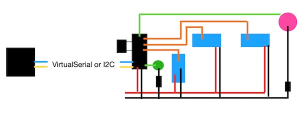
where the blue boxes represent the servo motors, the pink circle the “finger” microswitch, the green circle the four LEDs and the small black rectangle the external crystal that ensures correct timing in the microcontroller (large black rectangle). Red lines are Vcc, black lines GND, green is signal, orange is command, and the blue/yellow lines are TX/RX over the serial bus.
This cartoon translates into Eagle as shown below. A small capacitor was connected between Vcc and GND to smooth out any electrical noise in the input signal to the microcontroller. The RST pin was tied to Vcc through a resistor to ensure it didn’t waver during operations. The LEDs were all connected between Vcc and their respective pins on the microcontroller. This meant that the logic was reversed - they would light up when the pin was sent low (FALSE).
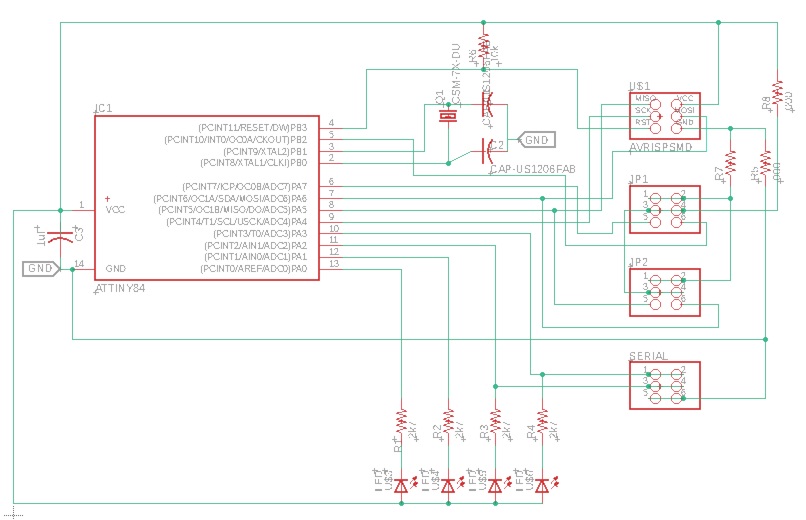
The updated Eagle files are here: SCH/BRD
Overall Circuit
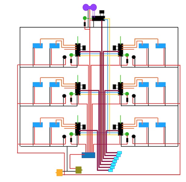
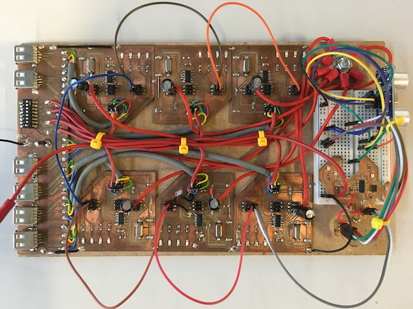
The leg boards were integrated into the overall circuit as shown below.
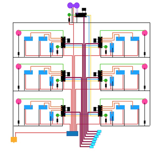
where the previously defined symbols are retained. The new darker red lines represent the ISP headers (MOSI, MISO, SCK and RST) which were routed from the individual boards to USB-A connectors on the “foot board” where they could be interfaced with an Arduino via the cyan connectors. The darker blue rectangle is a bank of switches to allow individual leg boards and/or the controller board to be switched off. The yellow connector at the bottom left leads to a bench-top power supply. At the top of the figure, the sonar unit is represented in purple.
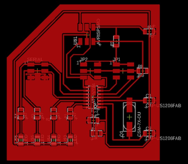
The dark red and scarlet lines down the centre of the figure above make up the power side of the power/data bus mentioned earlier. They consisted of signal cables and larger diameter (AWG 14) wires connected to the “foot board” where all of the connectors were fastened. The nets and layout of the foot board are shown below.
The Eagle files are here and here.
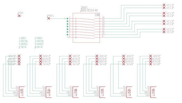
It didn’t really matter which pin of the USB-A socket was connected to which pin of the ISP header, as long as the cable I designed to connect the USB-plug to the Arduino was also wired accordingly, but I did want to avoid any problems with accidentally connecting a real USB cable to the sockets, so I made sure that RST would never be connected to GND. I connected the SCK pin to what would be GND in the USB standard, and MOSI/MISO to the other two, as shown above.
The serial data side of the bus was achieved with jumper wires connected between the relevant headers of the leg boards and the control board at the front of the machine.
Definite Layout
The initial prototype demonstrated some design weaknesses that needed to be addressed. As discussed later in the power chapter, it turned out to be necessary to separate the power supply to the logic circuit from that provided to the motors. It was also obvious that the current demand from the motors during start up was instantaneously too much for the power supply, so large capacitors were integrated into the final circuit layout. These are represented by black circles in the diagram below. The third servo on each leg has now been removed, as have the microswitches, which were never implemented. The second power supply connector, represented in khaki green, leads to the 5V power supply from an external Arduino which was also used to program the microcontrollers.
In the final layout, no further PCBs were designed, but the power part of the bus was enlarged with six new AWG 14 wires that met at a hub near the front of the robot. A new header pin was soldered to the input to the leg board switch bank, where the 5V supply for the logic could be connected, while the large plastic banana plug connector was retained for the connection to the bench power supply. The serial connection between the boards was made with jumper wires between the relevant headers on the leg boards.
The final addition to the electronics was the sonar unit. The ultrasound device, HC-SR04, has four pins: VCC, GND, Trigger and Echo. I first used this device back in Week 10. The device was added to the breadboard and wired in. The Trigger line went to the MOSI pin of the bird board, and the Echo line to its MISO pin.
Manufacture
PCB Milling
Board manufacture was all done in house (or “in garage” during the lockdown). The workflow looked like this:
- Finalise the board and ratsnest the copper popur into place.
- Export the file as an image, with 1500 dpi resolution.
- Use the dimension tool to size the outside of the copper pour on the trace (in x and y). Write that down.
- Import the image into GIMP.
- Cut the image to exactly the edges of the copper pour.
- Scale the image (image menu)
- Write down the calibration factor in mm/pixel.
- Export the image as a .PNG file
- Undo the changes
- Cut the image to exactly the border of the board.
- Apply the calibration that was written down in step 7.
- Erase everything out of the middle of the board, leaving a black rim.
- Export the image as a .PNG file (obviously with a different name).
- Close GIMP
The resulting images are shown here:
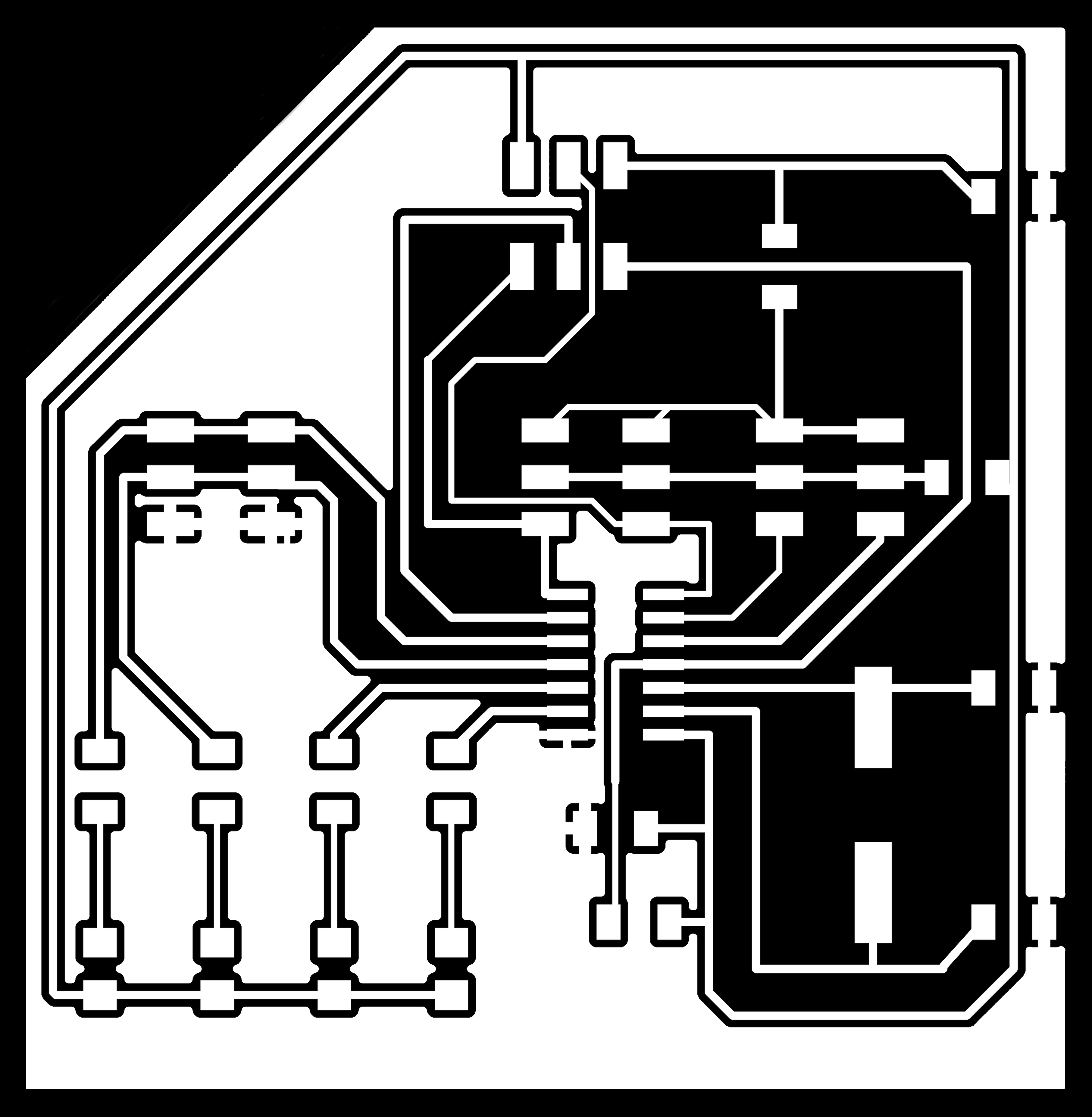

Scaled PNGs in hand, the next step was to run them through FabModules. Here I followed the procedure described in the Group Assignment and milled the board on the Genmitsu. The cutting went ok and produced the following:

The process was identical for the “foot board”, which was made using the following image files (which were turned 90 degrees in Preview so that I could cut along the long edge of the board blank.)

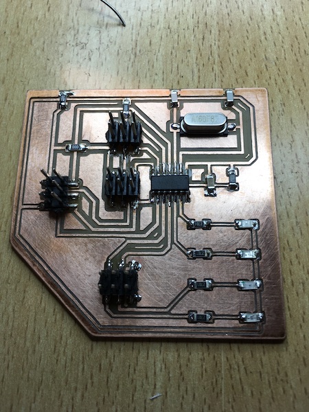
The resulting board, soldered into the robot, is shown below:
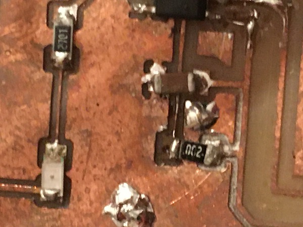
Quality Issues & Repairs
The PCB machining with the Genmitsu mill I had in my garage lab produced results of varying quality. That, coupled with not always ideal soldering conditions and skill, meant that pretty much every board had to be repaired in some way. Some examples of the “Frankenboarding” process are shown below. See the Project Diary for details.
Smoke Test
To burn the fuses, I used my UglyDuckling FabISP and the Arduino IDE with settings appropriate for this board:
The “avrdude done. Thanks.” line was always good to see.
Assembly
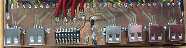
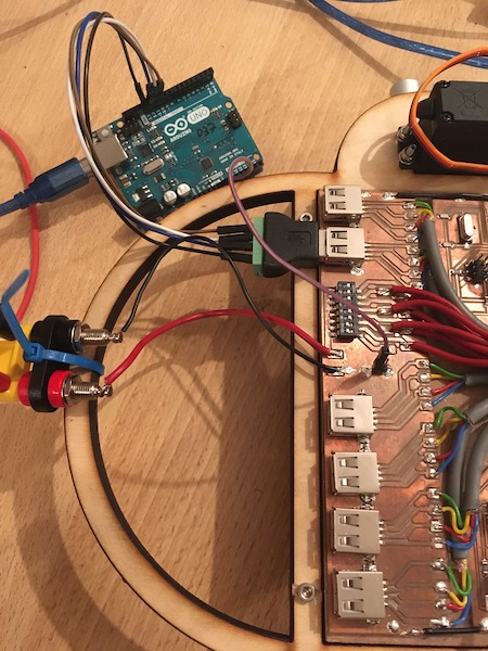
The PCBs were fastened to a piece of MDF dimensioned exactly to fit in the plywood frame of the chassis. As the PCBs were all single sided, it was possible just to use double-sided carpet tape to hold them in place. This had the advantage that replacement was straightforward when necessary.
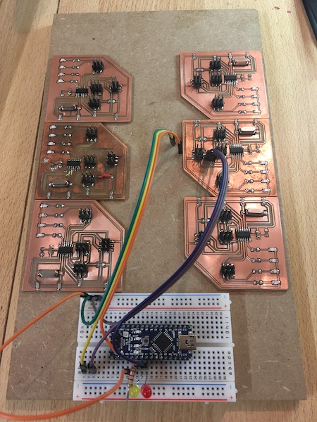
A breadboard was added to the MDF for prototyping purposes. Initially the overall control was done with an Arduino Nano, but this was replaced in the final version with a board of my own design and build (the swan board from Week 9).
I soldered leads between each of the breakout pads on the new PCB and the base of the corresponding pin headers on each of the leg boards. I had to juggle soldering irons since the big copper wires sucked all of the heat out of the tiny iron I used for the boards, but the big iron was just too clumsy for the precision soldering on the boards. I then cleaned up the cabling, and here is the result:
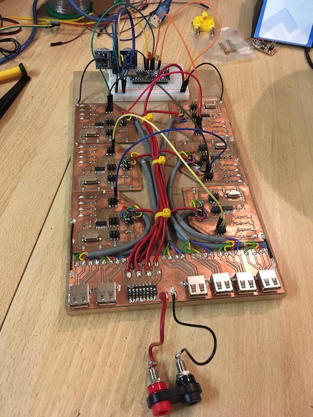
The USB-ISP cable then connected the four pins to the Arduino Uno in the usual way, as shown in the photo below. Notice the additional ground wire that connects the Uno to the robot. There was a ground path through the power supply and the real USB cable to the Uno from the computer, but it turned out not be stable enough for the programming, so I soldered the pair of pin headers to the copper pour of the power distribution board.
Power
Specification
The requirement for the power system was that it could provide sufficient current at a constant 5V to supply both the logic circuits and the servo motors. The logic circuits did not draw much current (ca 0.2A in total) at any time, but they were very sensitive to dips in the supply voltage. The motors were rated to draw as much as 2A each, but in practice rarely drew much more than 4A all told.
The specification for the power supply was therefore a constant voltage supply able to produce 5A at 5V.
Solution Principle
Initially there was a plan to power the robot with batteries so that it could operate independently. Time was however not cooperative, so the decision was made to run the machine off a bench power supply that could deliver 5A at up to 30V. The power would then be distributed throughout the robot over nets on the PCBs and a multi-wire cable.
Module Structure
The power supply system consisted of a PCB with several connectors, including both programming and power plugs, as well as a bank of switches which allowed each of the individual leg boards (and the main control board) to be independently powered or isolated.
Preliminary Layout
The first design used a common net to power both logic and servos.
Definite Layout
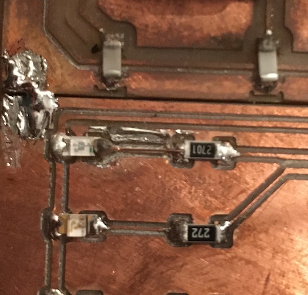
During the first trials, it became obvious that the bench power supply was struggling to provide constant voltage power to the logic during the short periods when the servo motors started. The high start-up current (near the limit of the power supply) demanded by the motors caused the voltage to dip, which randomly reset the microcontrollers and made operation impossible.
The modification to the definite layout was then to separate the servo and logic power nets. The logic circuits were powered by a USB connection to a computer and the servos were powered by the bench supply. To deal with the short duration peak current demands, a large capacitor (100uF) was added to the design across the servo power circuit on each leg board.
Manufacture
The final modifications to the electronics board to incorporate the rerouting of the power were done primarily with a soldering iron. A new set of six AWG 14 wires were fed under the original bundle of power wires and soldered to the power pin of what had been the third servo connector. The 100uF capacitor was also soldered to the pins of that erstwhile connector. Crimp terminals were added to the other end of the power wires, which were then all connected with a screw terminal at the forward end of the base board.
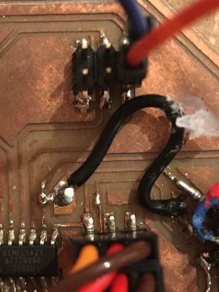
The bird board from Week 9 was attached to the breadboard with double sided tape and jumper wires used to connect it to the sonar unit. Its ISP pins were also connected into the breadboard, as two of them also doubled as RX/TX lines to communicate with the sonar unit.
The final layout is shown here:
Mechatronic Integration
The mechanical and electronic elements of the robot were integrated to create the final physical beast.
Definite Layout
The CAD model of the integration is shown in the figure below.

The CAD model does not show the foot board, nor does it properly represent the wire-based power/data bus, which was originally intended to be a PCB. That plan was abandoned quite early on in favour of the better conductive capacity of the AWG 14 wires over very thin PCB traces. The CAD model also shows an Arduino as the main control board. This was replaced as indicated above with my own board, for which I had no Fusion360 model.
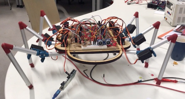
Assembly
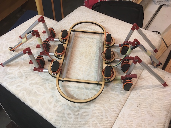
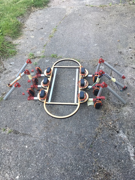
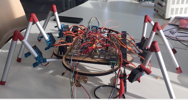
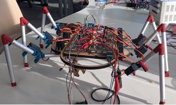
The final assembled version of the robot is shown in the following portrait, in which it’s actively standing and ready to rock.
Software Architecture
A robot is more than a collection of mechanical and electrical bits. It also needs some logic, a set of commands to interpret its world and react accordingly.
Specification
The logic circuit must generate the gait pattern, command the legs to move, and ensure that the machine does not crash into anything. It should be modular, with individual localised control over the leg movement and central decisions about sensing and gait dynamics.
Module Structure
The modular structure consisted of the “bird board” (see Week 09) overall controller as a central pattern generator and 6 individual “leg boards” which controlled the servo motors in the legs. The requirements of the software on each of the boards were:
Bird Board - read the sensor - generate the gate cycle - determine movement pattern - send commands to leg boards
Leg Boards - receive commands - operate servos
Communication between the boards was accomplished using a serial protocol.
Preliminary Layout
Leg Control
As a first step, the first two motors were run using the AtTiny and the PWMServo_v2 library via the Arduino IDE. A few adjustments were required to use that library with the ATtiny84. The mods were provided by “pxgator” on the Arduino forum. Basically it’s just a question of adding the following code to the PWMServo.h file:
#elif defined(__AVR_ATtiny84__)
 #define SERVO_PIN_A 6
 #define SERVO_PIN_B 5
The functional servo pair is shown below in operation (look carefully to see the dial turning on the second servo).
The sketch is here.
Abandon Library
The ATtiny pinout shows four PWM pins, but the datasheet only really talks about two, and most libraries are unable to do more. To control more than two servos from a single AtTiny, more specialised code is required. One such solution is avaiable here. By removing all of the additional code the author had included to control his robot, I was able to make a this sketch to generate the following excitement:
The secret to Tyler’s code was that it controlled the servos directly, without relying on any libraries. Instead he directly implemented the specification following the datasheet. The reduced overhead was appealing, particularly with the limited memory on the AtTiny microcontrollers.
A first go at a rowing movement is shown below:
Now that it was moving, the next step was to control the motion with a microswitch. I soldered some jumper wires onto the switch and plugged it into the fourth header, connected to pin 8 (arduino numbering). A quick update to the code made the movement dependent on the state of the switch. It worked exactly as expected:
Central coordination
The goal is an alternating tripod gait. That means that three legs remain in contact with the ground while the other three are lifted. All six motors are then moved forward, and the lifted three are put back on the ground. Once the weight is distributed among the six legs again, the second triple is lifted and the pattern repeats. In this way, the rover remains stable at all times.
In my little rover, the tripods are designated “red” and “yellow”, for the colours of the LEDs I plugged into the Arduino Nano that coordinates the motion. Each of the legs begins its stereotypical motion when one of the input pins (pin 9) goes low. In principle then, all I needed to do was wire legs FR, ML and BR to the “red” pin on the Nano, and FL, MR, BL to the “yellow” one, then wait for the pin to go low before starting the motion.
The pattern is there among the broken legs, but it’s obvious that a different solution is required. The response of the leg boards to the commands sent by the Arduino Nano just wasn’t reliable enough, and the motion fell out of synchronisation.
Definite Layout
The first version of the software architecture simply had the legs responding to a low signal on their input pin. The driving Nano sent that low from one of its output pins along one bus to boards 1,3,5 and from a different output pin along a different bus to boards 2,4,6.
Now in this version, the controlling board (now also a self-made board - the Swan Board from week 09) was set up to send a serial sentence along a single bus to all boards at once. Each of the boards read the sentence, decided if the message is for it, and if so, followed the command. If the message was intended for another board, it was simply ignored.
Sofware Serial Communications
The AtTiny boards do not have serial ports built in, but there is a handy library called SoftwareSerial which did the trick nicely. The controller (swan board) used the following sketch to send:
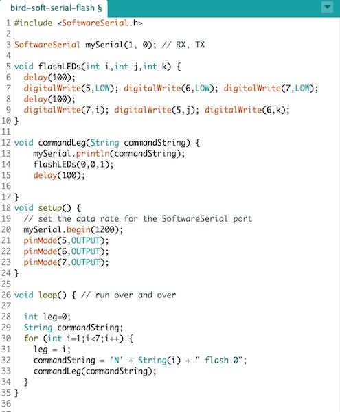
The first two lines set up the Software Serial library and created an object. The subroutine flashLEDs flashed the LEDs according to a binary pattern on the three integer parameters and, importantly, introduced some delays. These were not just necessary to identify the flashing LED pattern for debugging purposes, but they were also crucial for the timing control, as they allowed the servos to complete their actions before the next command was sent down the data bus.
The commandLeg subroutine put the command out onto the serial bus, flashed some LEDs, and again put some delay into the system. Next the built-in setup subroutine initialised the Software Serial communication and set up the LED pins. Finally the loop sent the message to the serial bus. The message was always formatted thus:
"Nx y**** zzz"
where x is the leg number identifier, which is one of:
- (0) no legs (eg for sensor comms)
- (1-6) for each of the legs individually, or
- (7) all legs should respond simultaneously
y**** is one of:
- flash - just flash the LEDs
- sweep - move the leg forward or aft
- heave - move the leg up or down
Note the **** characters are not important, just that there are exactly four of them.
and zzz is the argument (angle) of the movement command (argument of ‘flash’ is 0).
Each of the legs used the following sketch to listen for commands.

The sketch is available below.
Here is the system in action.
In the video, the LEDs on the swan board at the front of the beast generate a binary pattern indicating which leg is being activated. Blue is the most significant bit, green the middle, and yellow the least significant. Each of the legs then deciphers the message and flashes red when it’s been received, then flashes yellow if the message was intended for itself.
Leg Movement
The leg servos produced two movements: the shoulder swept the leg fore and aft, and the elbow heaved it up and down. The leg board sketch was set up to read the software serial commands, decipher them, and then action the leg servos or LEDs accordingly.
The code is available for download below.
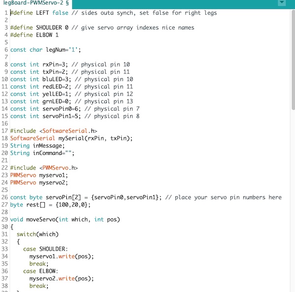
The sketch was in x parts. The header included some libraries and defined a series of constants, the most important of which was the legNum. This was the identifier each board’s sketch looked for in the serial commands to identify whether the message it had deciphered was indeed intended for it.
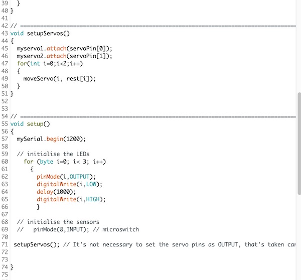
The next block was a pair of subroutines to control the motion of the servos. In setupServos(), the resting position of the servos was also set.
The setup subroutine initialised the Software Serial communication, set the LED pins for output and flashed them in sequence, then initialised the servos to the resting position.
The loop subroutine had two parts. The first read and deciphered the serial message, flashing the red LED to indicate the message had been received (note the blue LED flashed on its own due to the serial signal on the bus). The second part decided what to do with the command. The identifier (2nd character of the string) was first checked, then the first letter of the movement word was extracted, and the appropriate servo was called to move to the angle indicated in the argument. The green and yellow LEDs were flashed in the following pattern:
- green: Sweep
- yellow: Heave
- both: Flash
In the ‘sweep’ command section, the left side legs (4,5,6) were programmed to sweep in the opposite direction from the right side ones.
Downloads
- Bird Board Main Control
- Leg Boards Leg Control
Gait Patterns
Specification
The objective I set for this robot was to demonstrate coordinated movement of its six legs so that it could walk forward. Additionally it was to stop before crashing into an obstacle.
Other elements of the specification would include, among others, speed, stability, sweep and heave angles. For the purposes of this project, it was deemed sufficient just to demonstrate the feasibility of the movement. The two movements to be demonstrated included push-ups in place and forward locomotion.
Solution Principle
To achieve the objective set out above using the mechatronics as provided, the software architecture would have to do the following.
For push-ups:
- heave all six legs up
- heave all six legs down
For a one-foot-ripple:
- indicate which leg is to move
- heave the indicated leg up
- heave the leg back down
- repeat for all six legs, then
For a one-foot-at-a-time gait:
- indicate which leg is to move
- heave the indicated leg up
- sweep it forward
- heave the leg back down
- repeat for all six legs, then
- sweep all six legs simultaneously back
For an alternating tripod gait:
- indicate which tripod is to move
- heave the three indicated legs up
- sweep all six legs forward simultaenously
- heave the first three back down
- repeat for the other tripod
Standing
To stand, the bird board simply sent the command
"N7 heave 120"
to make all of the legs go from limp (upper frame, below) to energised (lower frame, below).
Push-ups and Swing Dancing
To progress from standing to push-ups, the bird board code was modified to give the commands (pseudocode):
"N7 heave 120"
delay(1000)
"N7 heave 140"
delay(1000)
The robot had no trouble with the exercise, as is shown in the video below:
The second test of the new servo power was to have the robot swing back and forth. In this case the commands were:
"N7 swing 100"
delay(1000)
"N7 swing 80"
delay(1000)
The movement with all six legs at once can be seen in the video below, though the robot is supported on some blocks, so it is not actually dancing. Its best moves all happened, as with all great dancers, off camera!
Walking one leg at a time
The objective was to build a robot that could walk on six legs. To achieve forward movement, the requirement was that the legs swing themselves back (and therefore the body forward), then pick themselves up one by one and swing themselves back forward before heaving back down to the standing position. The commands were:
"N7 swing 100"
delay(1000)
for (i=1;i<7;i++) {
    "Ni heave 140"
    delay(500)
    "Ni swing 80"
    delay(500)
    "Ni heave 120"
    }
Though not particularly well balanced on its six legs, whose 3D-printed parts were all slowly failing at different rates, the robot walked successfully forward. In the video below, it has just broken one of its legs by tangling it with the back leg in some random errors during the startup sequence. It soldiers on nonetheless, as if determined to show the world what it can do!
Alternating Tripod
To generate the alternating tripod gait, a more detailed set of commands were required. The algorithm looked like this (pseudocode):
"N7 swing 100"
delay(1000)
for (i=1;i<7;i=i+2) {
    "Ni heave 140"
    delay(500)
    "Ni swing 80"
    delay(500)
    "Ni heave 120"
    delay(500)
    }
for (i=2;i<7;i=i+2) {
    "Ni heave 140"
    delay(500)
    "Ni swing 80"
    delay(500)
    "Ni heave 120"
    }
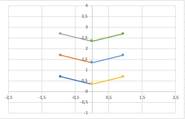
The motion this code should have produced is shown in the following simulation frames:
The robot has real trouble standing on three legs. It’s mostly to do with the distribution of load around the legs, which is itself a consequence of unequal zero angles on the knee servos.
Feedback Stopping
The last step for my final project was about having the robot respond to some external stimulus. For this purpose, I added an ultrasonic sensor to the front of the machine and connected it to the bird board via two of the ISP header pins (which were also the green and yellow LED pins). The ultrasound device, HC-SR04, has four pins: VCC, GND, Trigger and Echo.
The final walking demonstration is shown in the video below, including the stopping due to the detection of an obstacle (note the blue LED on the swan board lights when the hand is detected). During stopping the robot doesn’t swing its legs. Instead it only heaves them, as if jogging in place.
Victory
And with that, I’m going to declare victory and go home. It’s been a fun ride. I’m looking forward to tidying up the mechanical elements a bit before presentation day in January so that it walks a bit more evenly. I’ll also tidy up the wiring and replace the failing 3D printed parts. I’ve learned a lot and I’ll look forward to introducing my little beast to the world in Montreal next summer.
------------------------------------
Questions & Answers
There was a set of specific questions that our final project reports were required to answer. I’ve reproduced these here directly from the feedback system and provided summary answers that draw on the text above and/or on the experience I had during the final part of the project.
What does it do?
The machine is a six-legged walking robot. At the time of writing (29 November), it operates with a single gait in which each leg is heaved up, swung forward, and heaved back down. Once all legs have cycled through the motion, the robot swings the legs back, thereby moving its body forward. The pattern is repeated continuously until an obstacle is detected by the sonar sensor on the bow. When an object is detected, the robot only cycles through the heave up/heave down parts of the gait, essentially “jogging in place”.
Who’s done what beforehand?
There are many hexapod robots in the literature. They range from very simple systems using simple nitinol “muscle wires” to highly sophisticated walking logging machines designed for working in mountainous terrain. Pretty much every roboticist passes through the phase of building a 12-servo six legged robot at some point, so I’m climbing onto the shoulders of some pretty spectacular giants. Specifically for me there are four inspirations:
- Stiquito
- Bielefeld stick insect
- John Deere logging machine
- BREATHE (described in the first sections of this page)
The last of that list is a machine that my lab applied along with four European companies for 4M Euros to build in life size. We didn’t get the money, but this project is about building a platform which I can use to explore gait patterns and the programs needed to generate them.
What did you design?
I designed the robot frame, its six two-servo driven legs, the electronics (including the PCBs) to control and power each of the legs. I designed a central controller board and added an obstacle avoidance sensor. I also designed the control algorithm to drive the system forward using a simple one-leg-at-time gait. Finally I designed a cover for the whole machine.
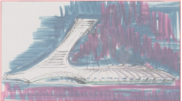
The cover is inspired by the Olympic Stadium in my home town of Montreal. The tower was 3D printed as one piece, while the rest of the cover was milled in two operations on the CNC machine (one side was milled, then the part turned over, and the other side was milled.)
What materials and components were used?
The leg shafts were made of aluminum tubing while the joints were made of 3D printed PLA. The servo motors were CoT products. The frame was lasercut plywood. The PCBs were cut in the usual way from copper plated stock and stuffed with the relevant electronic components. Each of the boards (7 in all) was based around the AtTiny84 microcontroller, and included an external crystal (either 16 or 20Mhz), signal LEDs with resistors, capacitors to smoothe the power and signals, and headers for communication with the other boards and the servos. The sonar sensor was a CoT product.
Where did they come from?
All of the parts were sourced either from the FabLab inventory or were purchased directly from Amazon or Reichelt Electronics.
How much did they cost?
The Bill of Materials is available here. The total cost for the robot was 226.01€.
What parts and systems were made?
| Part | Made/Bought | Material | Source |
|---|---|---|---|
| Leg shafts | Made | Aluminum pipe | Local Hardware Store |
| Servos | Bought | Higher torque | Generation Robots (France) |
| Leg Joints | Made | 3D printed PLA | FabInventory |
| Body Frame | Made | Plywood | FabInventory |
| PCBs | Made | PCB Stock | FabInventory |
| Electronics Board | Made | MDF | FabInventory |
| Power Electronics Boards | Made | Specialised Components | Reichelt |
| Cover (hull) | Made | 3D Milling POM | Donated Scrap Material |
| Cover (tower) | Made | 3D printed PLA | FabInventory |
What processes were used?
| Process | Used for |
|---|---|
| Lasercutting | Frame |
| 3D Printing | Leg joints, hull tower |
| CNC Milling | PCBs, hull cover |
| Soldering | PCBs |
What questions were answered?
There were several primary questions.
-
Was the mechanical design correctly specified? The answer to was “almost”, in that the motors can lift the robot and move the legs, but the dynamics are not pretty. The answer to the second is in the section above called “Mechatronic Integration.”
-
How do I best lay out the boards to move the legs in a synchronised way? The architecture of the electronic control, using the software serial library, worked out just fine. The local boards were able to move the legs as requested by the central controller. They were also able to detect when the legs touched the ground, though this was not implemented in the final walking beast.
-
Would a simple power distribution system work, or would I need to split the logic from the power electronics? The answer was the latter.
-
What gait would best suit the machine I’d designed and built. Originally I had hoped to build a robot that could walk using an alternating tripod gait. I was able to write the code to do that, and the machine could achieve the gait pattern when not carrying its own weight, but once standing on its own six feet, the alternating tripod was insufficient, so I went with a one-leg-at-a-time gait, which worked.
What worked? What didn’t?
The code worked well. The electronic communication between the boards was fine, and the power transmission was a success once I had split the logic from the high power. The legs worked out in the end. The robot could stand and do push-ups on four motors, and walk one leg at a time on all six.
The disappointing part was that I had underspecified the motors. There was simply not enough torque available to stand the robot up on three legs to allow it to use the alternating tripod gait I had been aiming for.
How was it evaluated?
The basic objective was to see the machine move. I set the following series of tests for it to attempt:
| Task | Result |
|---|---|
| Move individual legs in stepping pattern | Passed |
| Coordinate six legs in a rowing motion | Passed |
| Stand up on six legs | Passed |
| Stand on a three-legged tripod | Almost, but no |
| Stand on five legs | Passed |
| Push Ups on six legs | Passed |
| Stand in place, move one leg a time | Passed |
| Walk forward, one leg at a time | Passed but messy |
| Walk forward, alternating tripod | Failed |
| Detect obstacle | Passed |
| Stop before hitting obstacle | Passed |
What are the implications?
The implications for me are that I’ve managed to design, build, tune and operate my first ever six-legged robot using a set of servos I had specified and components I had built. There’s a long way to go before I can claim any success similar to the Bielefeld team, but I had to start somewhere.
The development of this robot isn’t finished. There is some weight optimisation possible - the heavy MDF board that gathers all of the PCBs together is unnecessarily robust and could be replaced with some elegant 3D printed plastic or indeed the whole modular design could be milled from a single piece of PCB, which would reduce the weight of the wires and connectors and nicely clean up the whole internal part of the machine.
With a little more practice, it might be possible to rescue a more stable gait from the robot. The pitching movement observed in the final movie I made was caused by the centre of mass being too far back, so that when the rear legs were lifted to be moved, the whole machine tipped up at the bow. By recentering the middle pair of legs, it might be possible to keep them behind the CoM and hence distribute the weight to allow the rear legs to move without tipping the machine. I’ll try that before the January presentation.
Finally, the biggest implication of this FabAdventure is that I’ve now got a solid start learning the skills I’m going to need to start my own FabLab. I’ve obviously got a long way to go, but with the support of the staff at the KaLi FabLabs and elsewhere in the university, I’m confident we’ll be able to make a solid go of this in the coming years.
Links
Presentation
CAD
- Fusion360 Archive
- Full Robot STL format 6Mb so stored on uni server
- Legboard BRD
- Legboard SCH
- Birdboard BRD
- Birdboard SCH
Sketches
- soft serial tester
- sonar tester
- main driver
- flash leg LEDs
- do pushups
- swing dance
- stop
- legboard sketch
Bill of Materials
Please follow this link.
License
If you want to reproduce this robot for yourself, please feel free to do so, but do please also give me credit, and more importantly, tell me about your work! Officially this work is licensed under CC-BY-SA.
------------------------------------
Epilogue
After the successful final evaluation by both the local and global examiners, I decided to keep going on the robot to spiff it up a bit.
Decoration
Once the robot was walking, it was time to add some more exterior design. To celebrate our meeting in Montreal next summer, I took some inspiration from my home town’s famous Olympic Stadium.

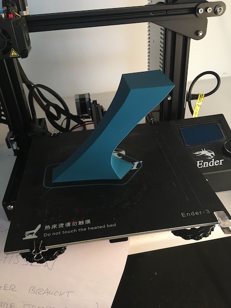
I created the simplified hull and tower in Fusion360.
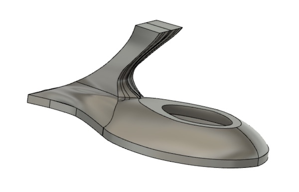
I split the tower off the hull and printed it using the Ender-3. I used the default settings and printed it vertically. Here’s the result:
The main cover I prepared for 3D milling using the manufacturing environment in Fusion360. I set up the model so that it could be cut in two goes, once from the top, then flipped and cut from what had been the bottom. To make the clamping possible, I included a set of blocks attached to the model, through which I drilled holes for bolts to fasten the block to the mill bed.
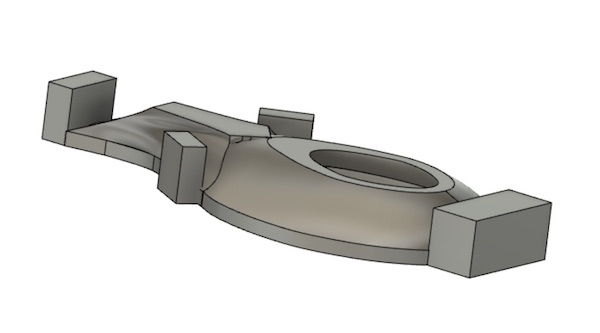
I had a block of POM lying around the lab, which a friend had donated a few months back. To fix that block to the bed of the CNC mill, I placed a set of holes in the design, then lined up the block on my manual mill and drilled the 6mm holes straight through. I also included a single empty hole which I set as the origin for the Fusion 360 model. When I flip the block to machine the other side, that hole will allow me to line up the two sides.
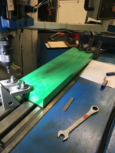
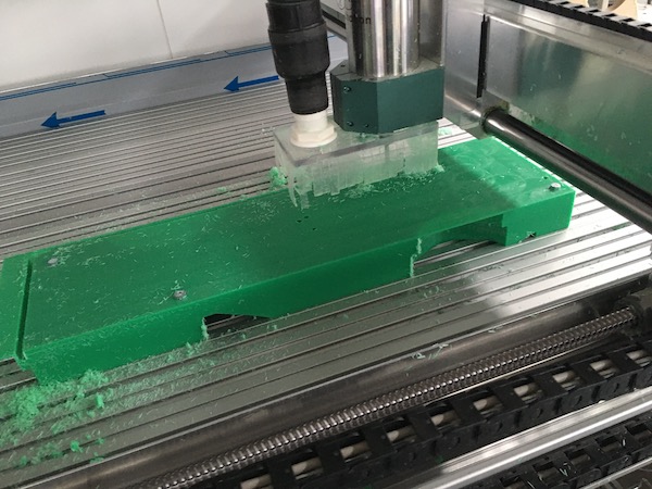
I used a 6mm two-flute up-cutter and the adaptive clearing strategy. RPM was set at 7500 (which I ramped up to 9500 while watching the machine), the cutting speed at 200 mm/min (ramped to 300 mm/min at the machine) and the plunge speed at 90 mm/min.
The first side cut ok. Here it is completed:
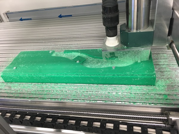
Then the trick was to flip it over. I tried just to flip the model over in Fusion 360 and create a new adaptive processing block, but that created error messages saying the orientation of the tool was wrong. I couldn’t figure out how to fix the error, but in the end it was easy just to delete the first adaptive job and start over with the second one. Once I picked the axes carefully, lined up at the other end of the marker hole I’d drilled before, and set the stock box to the size it had after the first cut, all was straightforward. I rolled the POM block over, lined it up carefully on the marks and clamped it back down. It got off to a good start:
I ramped up the feed to 500 mm/min and the spindle speed to 9500 rpm. The cutting of the second side went well, but I did forget to set the resolution to the same fine level as on the first side, so I had to machine it a second time to clean it up.
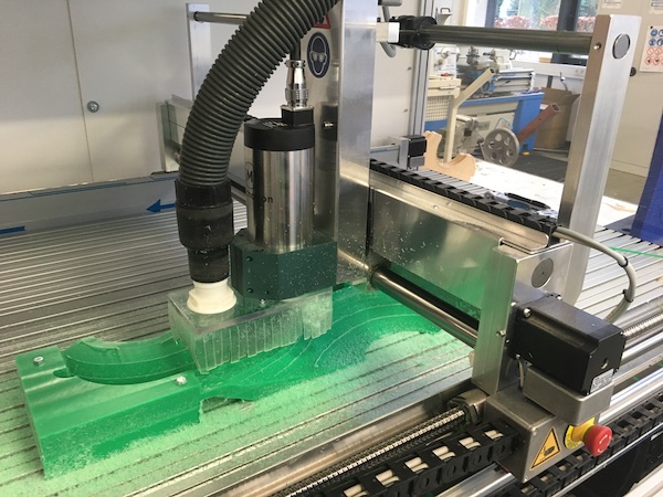
One thing that didn’t go according to plan is the lining up. I used pencil lines to trace the block during the first cut, but lining back up wasn’t quite precise enough, so I had a shift of something like 200μm between the cuts. Annoying, but nothing a little additional sanding couldn’t fix.
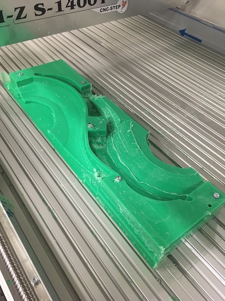
After the machining was complete, I used the bandsaw to cut the two halves out of the remaining block, then trimmed and sanded them to fit. I added some steel plates top and bottom of the front flat, and a leftover 3D printed bracket to the back. The tower was fixed to the base with bolts fit into threaded holes in the base of the tower. That won’t hold for long, so eventually I’ll have to cut some holes in the tower and insert some proper bolts/nuts. Here’s what the assembly looks like in position on the robot:

Main Board
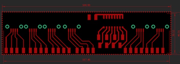
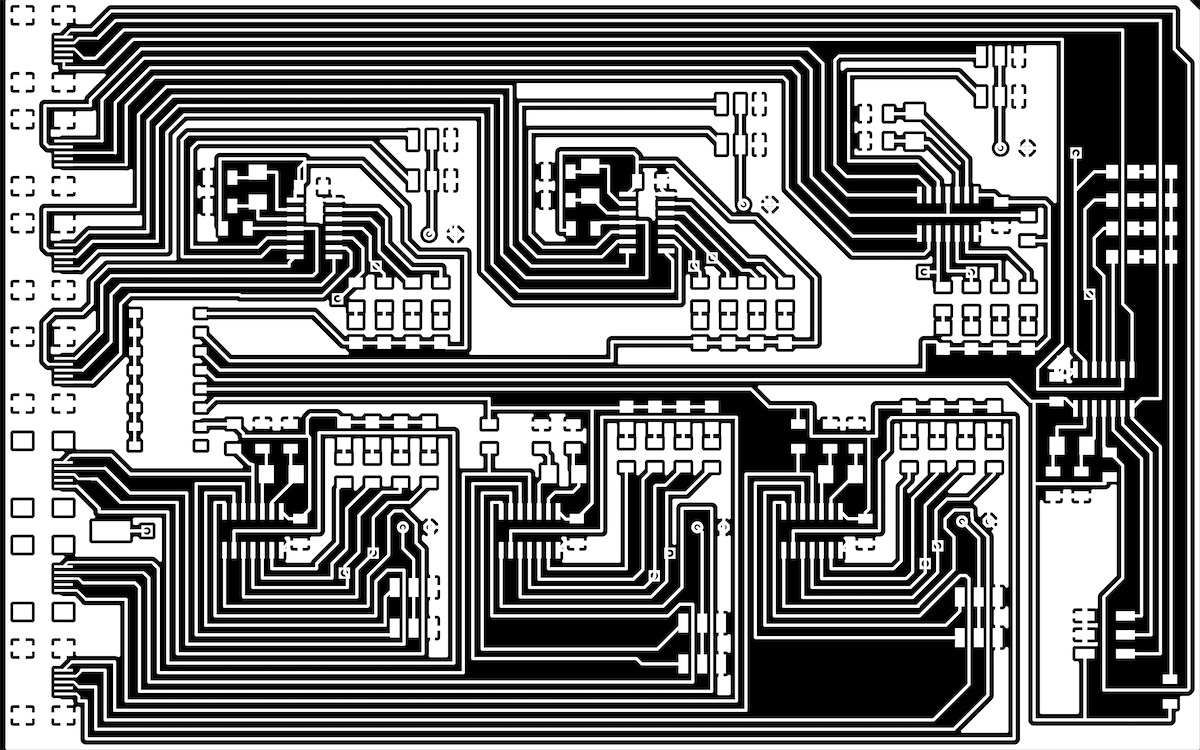
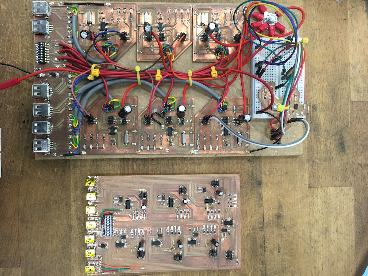
The original modular design and construction resulted in quite a large motherboard with lots of heavy, bulky wiring. I did my best to tidy it up with zip-ties, but it was clearly always going to be messy. So I decided to go for a new, single motherboard design. I kept the modular design based on AtTiny84 microcontrollers, but put them all on a single, one-sided 100x160mm copper clad stock.
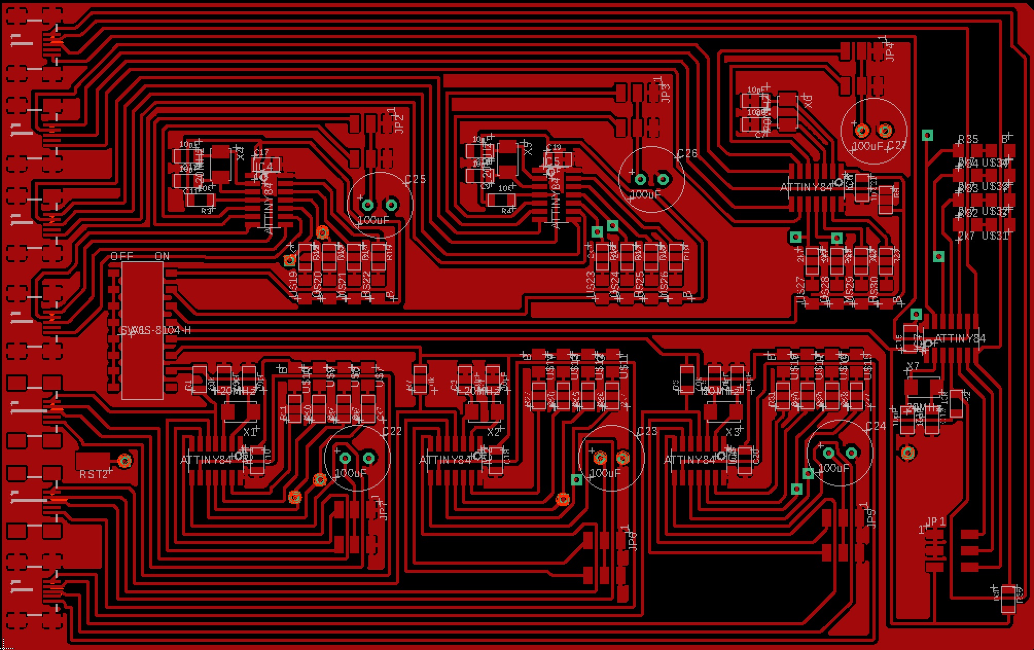
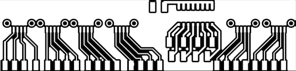
The circuit design is identical to the previous one, with the exception that there are now only two 3-pin headers for the servos on each leg. I’ve incorporated the base board with its USB connectors, though I’ve moved instead to mini-USB connectors. The main switch block has been retained, and all of the microcontrollers have their 1uF smoothing capacitors, external 20MHz crystals (with 10pF capacitors) and four signal LEDs. The servos receive their power from a separate power supply from the logic, and at each leg, I’ve included a big 100uF capacitor to help with surges. I couldn’t quite get the whole design onto a single side, so the serial connections and the servo power lines are run along the bottom of the board, with vias to bring them up where appropriate.
I machined the board following the usual instructions, though because I used the whole copper clad stock, I didn’t need the cutout step. Here is the thresholded image:
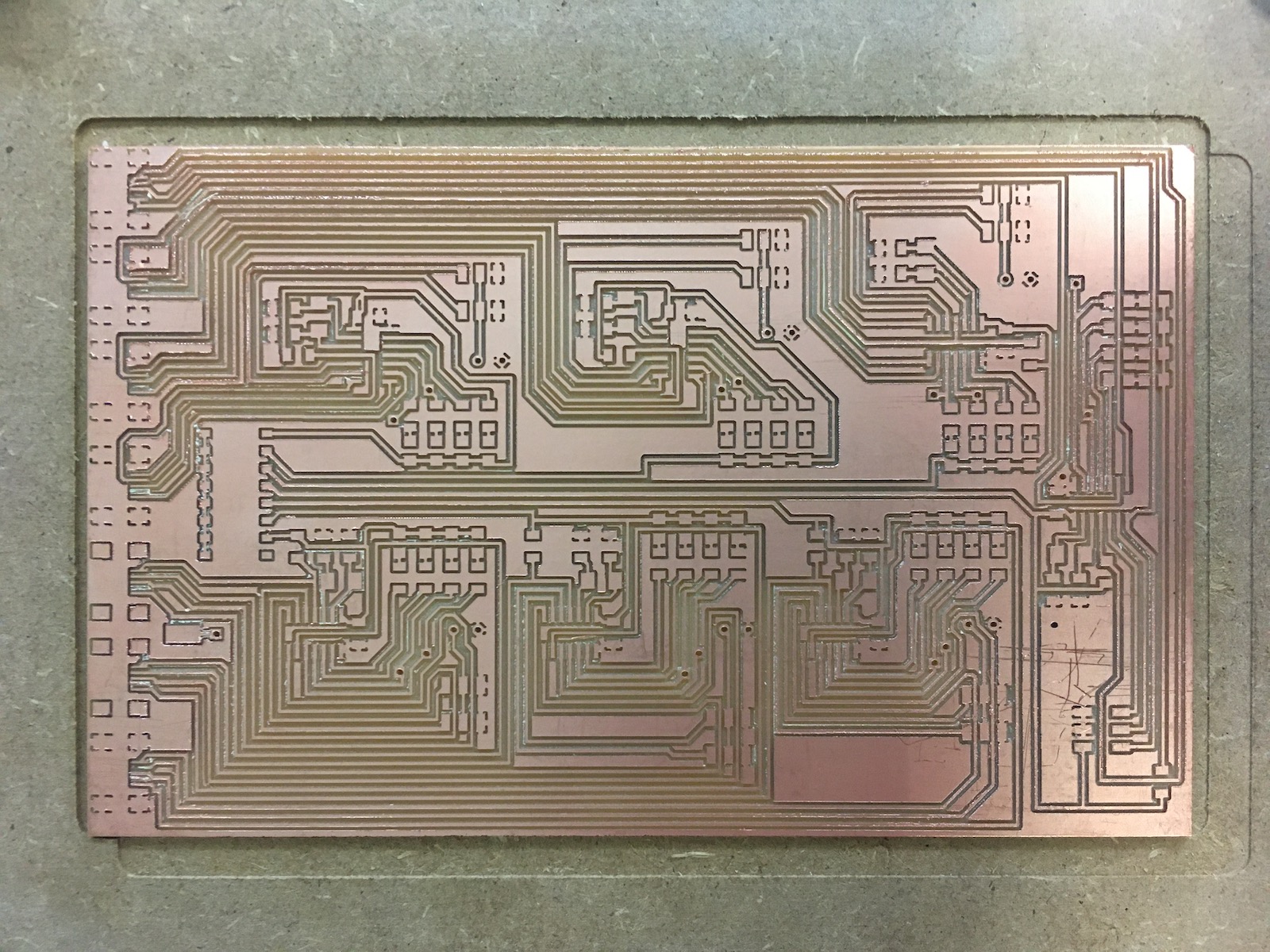
I used FabModules to make the G-code. I set the cutter to run at 2mm/s and at 9000rpm, then milled the board on the High-Z mill. It took five tries to get the cut right. The biggest problem was the fine resolution between the pads of the mini-USB ports. On the first few tries, the cutter just evaporated the copper in those areas. The solution was to make the traces narrower, but to keep the narrow parts very short. The board came out beautifully:
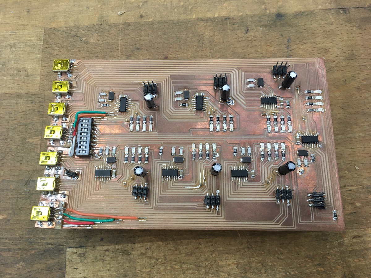
Stuffing the board went straightforwardly until I started trying to solder on the mini-USB ports. I made a wreck of two of them before I figured out how to tin the pads and place the component with fingers rather than tweezers (and even managed not to burn them!). There was a bit of panic when I realised I had ordered the wrong crystals, but DigiKey came through over the weekend. The final board, including some Frankenboarding to repair the damage to the two USB ports, looks like this:
The smoke test and fuse flashing went smoothly using an Arduino Uno. The second smoke test was also succesful, as I connected the external power supply to the servo/capacitor ciruit.
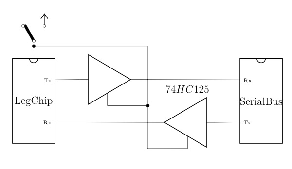
As I started programming the microcontrollers, a schoolboy error became obvious. The new permanent connections of the serial bus meant that when the leg boards were turned off at the switch, they were still powered by the TX output from the brain chip which powered them through their RX pins. Likewise, the brain chip itself was powered by any output from the TX pin from any of the leg chips. Neither of these is a particularly happy situation. The simplest solution would have been to simply run all of the serial bus wires into a pair of 8-connector female headers on the bottom of the motherboard and use a jumper made from a male header row. That would do for debugging, but it would have been impractical in the final robot.
The “proper” solution will be to use a tri-state buffer (74HS126) on each side of the serial bus. In this case, the buffer enable pin is connected to the local Vcc at each microcontroller. Only when that chip is powered on would the buffer allow the serial signal through.
To implement this part of the circuit, I’ll need to build yet another little board. That might or might not happen before the final presentation.
However, the objective of smartening up the robot’s guts has been achieved:
Programming Upgrades
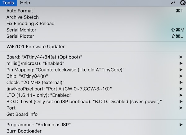
The first step was to note the changes to the Arduino IDE for the AtTiny84. There are a lot more options now available. The defaults are ok for most options, but several did need to be set to match the PCB layout and pin assignments I had chosen to use. The settings which were used are shown below:
With the simplification of the electrical design, there was no longer any need to use the more sophisticated PWMServo library, so I switched to the simpler, default Servo.h. The pins needed to be renumbered according to the new compiler arrangement. Otherwise the sketch is pretty much identical to the previous one.
Where I made the big changes was in the brain sketches. The first changes were just to the pin assignments and the patterns of LED flashing to provide feedback to the user. Then I added the commands to communicate with the LCD screen. These were sent along the serial line the same as the commands for the leg motions, just with the format “N8 xxxxx yyy”, where xxxxx could be “speak”, “count”, or “place”, as described in the UI board section below.
The same selection of behaviours was retained, and the last two were added:
- Flash LEDs
- Stand up on six legs
- Swing on six legs
- Push Ups on six legs
- Walk forward, one leg at a time
- Push Ups on three legs
- Walk forward, alternating tripod
The walking routines also included the detect and stop before hitting an obstacle segments, as before.
The three-legged pushups sketch is the precursor to being able to do the alternating tripod. It wasn’t possible to stand on three legs with the previous heavy wooden main board. The hope is that the lighter weight new board will make it possible. Of course, the new decorative top might nix that.
The alternating tripod gait is just the one leg at time motion in a different order. The robot heaves the three legs of a tripod up, sweeps them simultaneously forward, heaves them down into a three-legged pushup, then sweeps the three legs back relative to the body, which effectively moves the robot forward. The process is then repeated for the other side.
UI Board
The main communication with the robot has been via the LEDs on each of the microcontrollers. To improve the communication with the user, I added a 16x2 LCD with its own driver board to the front panel of the robot. That required a little 3D printed box and a PCB.
LCD driver circuit
Sticking with the AtTiny84 architecture of the rest of the robot, I designed a circuit to interface with the LCD. I included the usual 20MHz external crystal with its 10pF capacitors, a 1uF smoothing capacitor across the supply, and a 10k resistor from RST to Vcc. I used David Mellis’s LiquidCrystal library to operate the LCD. It has the useful feature that the output pins of the microcontroller can be assigned as desired, so I picked an order that made the circuit board easiest to route.
| LCD Pin | AtTiny Pin | Arduino IDE |
|---|---|---|
| RS | 10 | 7 |
| E | 11 | 8 |
| D4 | 12 | 9 |
| D5 | 13 | 10 |
| D6 | 6 | 3 |
| D7 | 5 | 2 |
| RW | GND | |
| VSS | GND | |
| VCC | +5V |
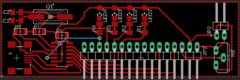
I included a 1k potentiometer wired between Vcc and GND, with the wiper connected to pin V0 of the LCD, to adjust the brilliance of the back light. The board layout looked like this:
I milled it on the High-Z following the now standard approach. I do need to make some checklists, though, to remind myself and others of the steps to go through at the mill. I had to redo the milling job three times because I forgot a step each time…
LCD box
Once the board and LCD screen were manufactured, stuffed and assembled, I could take some dimensions and design a simple but stylish box to house them. The box was to be mounted on the front panel of the robot top cover, for which I included four M4 bolts which screwed into threaded holes in the POM. The serial bus and power wires were fed through holes through the housing and panel.
LCD sketch
The driver sketch for the LCD board uses the SoftwareSerial library to communicate with the robot brain and the LiquidCrystal library to run the LCD screen. The code is available for download in little further below.
The code starts by defining an array of communication strings. These are called by number from the robot brain sketch. The serial communications are done the same way as for the leg boards. The LCD sketch is addressed as ‘N8’. Its commands include:
- speak: display the string specified in the argument
- place: position the cursor as indicated in the argument
- count: print a two digit number on the lower line at the cursor
The argument in the commandString contains three characters. The first indicates which line to print on (0 or 1). The second and third are either the string index or the number to be printed.
Updated downloads
- Motherboard SCH
- Motherboard BRD
- LCD board SCH
- LCD board BRD
- LegSection Sketch
- Brain Sketch
- LCD Sketch
Mechanical Behaviour
The new robot is lighter without its big heavy wooden motherboard and has no trouble now doing pushups.
It has more trouble with the cover, where the extra weight of the POM structure simply overloads the servos.
The problem was however quickly solved by increasing the voltage on the servo circuit and plugging it into the higher current side of the power supply.
Centre of Mass
One of the biggest problems with the previous design seemed to be that the centre of mass was not in the geometric centre of the legs. The robot pitched wildly up and down when either of the front or rear right legs was lifted. With the higher currents now available to the servos, they are more able to handle the load, so this problem may go away. We’ll see.
Gaits
This will be the plan for the development of the gaits.
| Task | Result |
|---|---|
| Move individual legs in stepping pattern | |
| Coordinate six legs in a rowing motion | |
| Stand up on six legs | |
| Stand on a three-legged tripod | |
| Stand on five legs | |
| Push Ups on six legs | |
| Stand in place, move one leg a time | |
| Walk forward, one leg at a time | |
| Push Ups on three legs | |
| Walk forward, alternating tripod |