This page is an archive for week 3 group assignment where the task was the following:
The following table is a summery of the characterized settings for the materials we used this week. The table contains the settings of our best trials. The rest of the details are explained thoroughly further down in this page.
| Machine | Material | Power | Speed | Frequency | Notes |
|---|---|---|---|---|---|
| USL PSL6MW (small) | Cardboard 6 mm | cut:100% engrave: 30% | cut: 12% engrave: 100% | cut: 500 engrave: 500 | kerf measured = 0.25 mm. |
| USL PSL6MW (small) | foam (corefoam 4.7 mm) | cut: 40% | cut: 100% | cut: 1000 engrave: 5000 | kerf test is not applicable for foam. Due to curve nature occurring on the cut surface, measuring the pieces together is impossible and they collide with each other, and measuring a single piece gives an inaccurate result. |
| USL ILS12.150D (big) | foam (corefoam 4.7 mm) | cut:60% | cut:7% | cut: 1000 engrave: 5oo | NA ( similar result as ULS PSK6MW) |
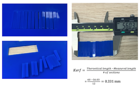
| USL PSL6MW (small) | Plastic (Cast Acrylic 3mm) color blue | cut:100% engrave: 26% | cut: 3.9% engrave: 100% | cut: 1000 engrave: 5oo | kerf = 0.331 mm |
| USL PSL6MW (small) | MDF 3mm | cut:100% | cut:5.0% | cut:500 | kerf = 0.266mm |
| USL PSL6MW (small) | Cardboard 6 mm | cut:80% engrave: 9% | cut: 7% engrave: 100% | cut: 300 engrave: 500 | Second Trial with cardboard settings, Thickness has been changed from 3 mm to 6 mm. Kerf measured = 0.25 mm |
| Trotec laser machine | Cardboard 6 mm | cut: 45% engrave: 40.05% | cut:2.5 engrave: 1 | cut: 1000 Hz engrave: 500 PPI | Kerf measured = 0.34 mm |
| USL PSL6MW (small) | MDF 3mm | cut: 100% engrave: 60% | cut: 6.4 % engrave: 100% | cut: 250 engrave: 500 | Kerf measured = 0.317 mm |
| USL PSL6MW (small) | Cast Acrylic | cut:50% engrave: 50% | cut: 100% engrave: 100% | cut: 500 engrave: 500 | Kerf measured = 0.25 mm |
| Trotec | MDF 3mm | cut:80% engrave: 10% | cut: 0.4% engrave: 100% | cut: 1000 engrave: 1000 |
I chose cardboard as my test material with 6mm thickness. And I started my test on the Universal Laser System machine.
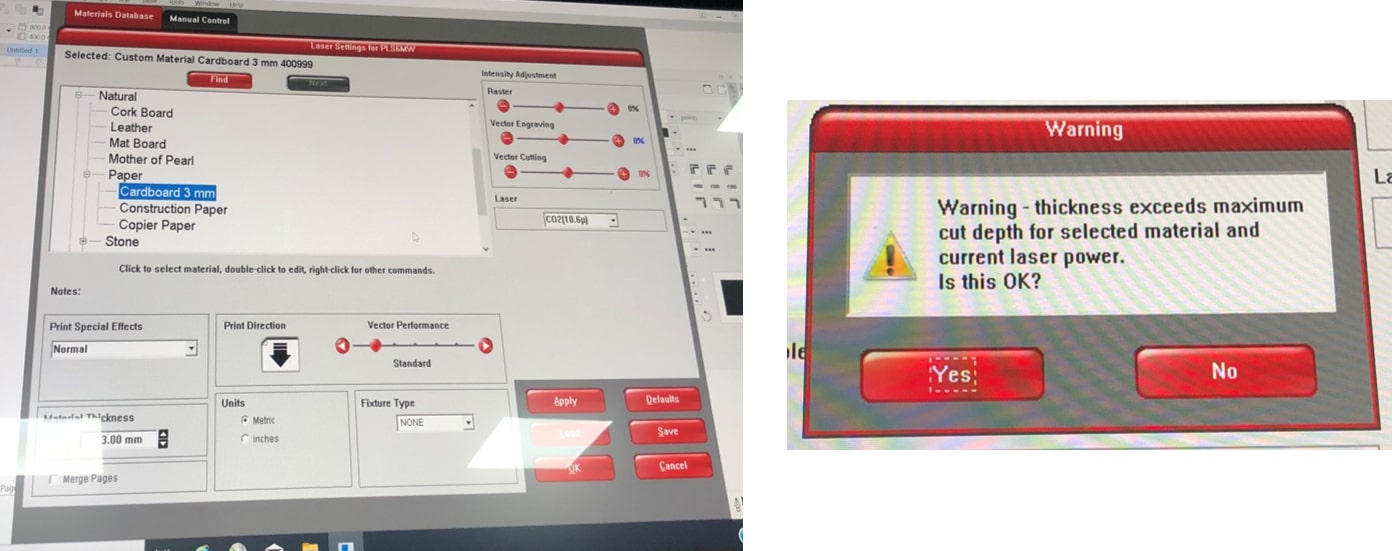
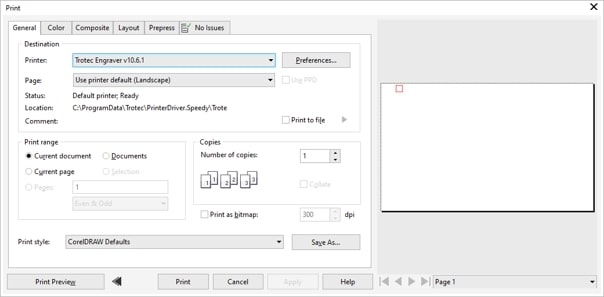
I created a simple rectangle on CorelDraw, made sure that the thickness was hairline and the outline was in red. Then I went to file tab >> print>> preferences, and changed the parameters on material database and manual control.
In material database I chose natural >> paper>>cardboard 3mm. When I tried changing the material thickness, an error message popped out, thus, I tried the settings on the default material thickness.
In the manual control, I kept the default settings for the speed and changed the power and clicked on set, apply and ok!
| power | speed | frequency |
|---|---|---|
| 50% | 27% | 500 PPI |
Then I opened the control panel of the laser machine. As the machine had Auto focus, I just had to navigate to my starting point using the focus pointer, then clicked on navigate to pointer which places the design on the point I chose previously. I made sure that the Filter was on and clicked on RUN.
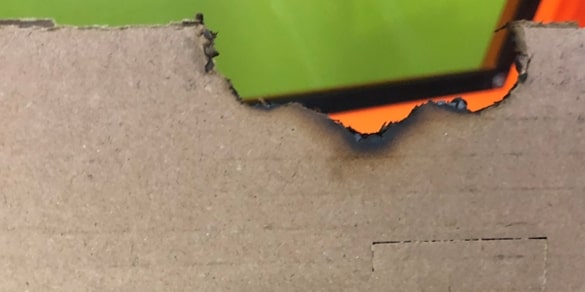
Needless to say that with these values of power, speed and frequency, the result was disastrous. As soon as the cutting started, tiny flames surrounded the design and the cardboard was slowly burning and spreading out.
I .. froze. I didn’t know whether I should take it out, or whether to keep it inside with the filer on with the hopes that the slowly burning cardboard would stop .. well .. burning! Knowing in the back of my mind that the latter of the two was wrong and I had to take action fast.. I took the cardboard and killed the dying ashes.
After recovering, I tried different settings using the procedure above.
| power | speed | frequency | notes |
|---|---|---|---|
| 50% | 27% | 500 PPI | Burned the material |
| 65% | 27% | 500 PPI | The cardboard was not cut all the way, no indentation can be observed on the back of the material. |
| 100% | 20% | 500 PPI | The cardboard was not cut all the way, slight indentation can be seen on the back. |
| 100 % | 15% | 500 PPI | The cardboard was cut all the way but it was still hard to remove. |
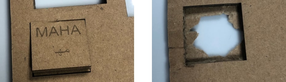
| 100% | 12% | 500 PPI | The perfect settings! the cardboard was cut correctly and removed easily. |
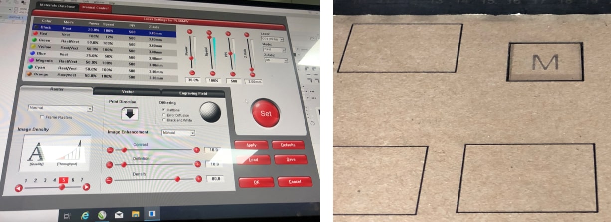
Next was the engraving, I added the letter M to my design and followed the same procedure, this time however, keeping , my ideal cutting values and changing the values for the engraving which was represented in black.
| power | speed | frequency | notes |
|---|---|---|---|
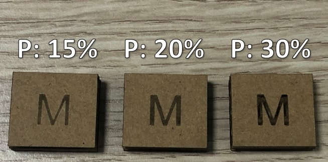
| 15% | 100% | 500 PPI | on surface engrave, slightly fade |
| 20% | 100% | 500 PPI | a bit deeper into the surface, darker engrave. |
| 30% | 100% | 500 PPI | penetrated through the first layer of cardboard, deep engrave. |
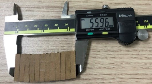
After making sure that the ideal cutting settings were achieved, I tried measuring the kerf of this particular laser beam. The kerf is a value that indicates the amount of material being “vanished away” by the laser beam.
That was done by creating a rectangle and cutting it into 12 identical pieces, then taking the difference in width and dividing by the number of pieces.
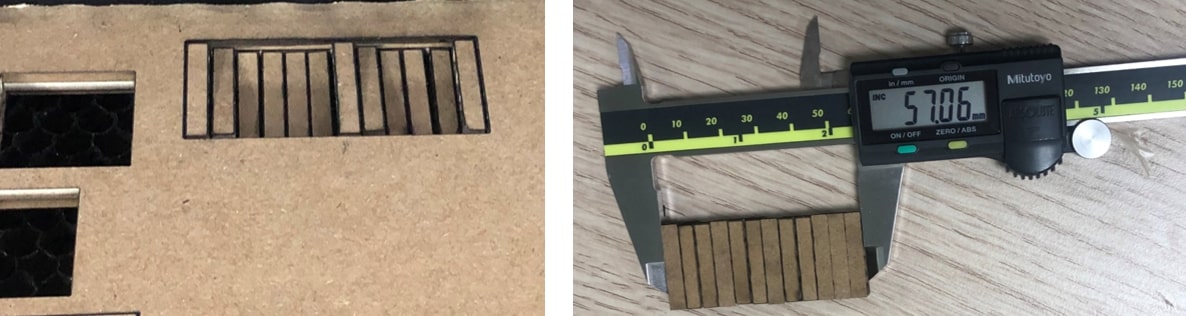
The kerf in the universal cutting machine measured to be 0.25 mm
Next, I tried the Trotec Laser machine, which admittedly was a bit different than the universal machine.
The first step here was to create a simple design, make sure it is in hairline thickness and it is outlined red for the cut, then go to files >> print.
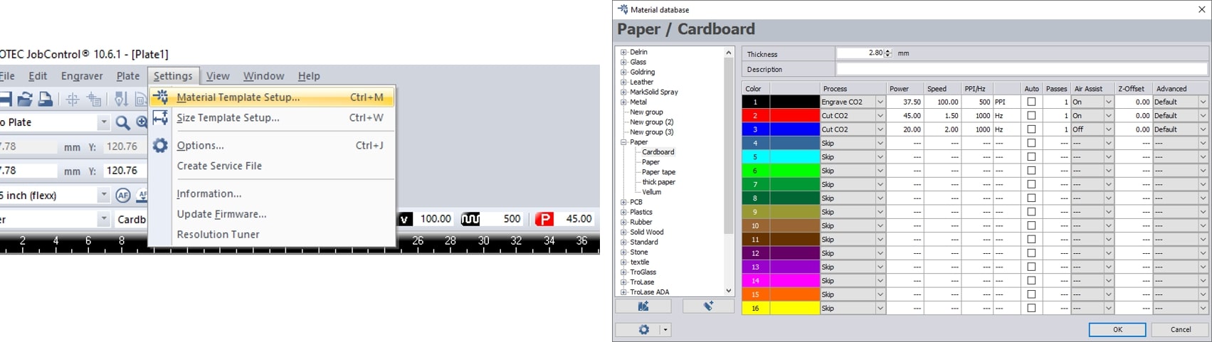
Then, contrary to the universal laser cutter procedure, the parameters are changed from the Troctec Job control software, where I clicked on settings >> material template setup which pops the material data base window.
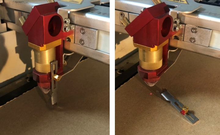
To use the auto focus we clicked on the up and down arrows at the same time, of which the machine automatically adjusts the height of the plate according to the laser beam.
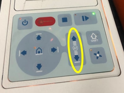
Then to increase accuracy the manual focus tool can be slipped on the side of the laser tool and the plate can be brought up manually until the tool touches the plate and falls down.
I tried different settings for the cutting but kept the engraving on the same settings since it worked perfectly.
Engraving
| power | speed | frequency | notes |
|---|---|---|---|
| 40.05% | 100% | 500 PPI | on surface engrave, dark and clear. |
Cutting
| power | speed | frequency | notes |
|---|---|---|---|
| 45% | 0.5 | 1000 Hz | The cut did not go all the way through. |
| 45% | 1.5 | 1000 Hz | The cut did go all the way through, however, the piece was hard to remove. |
| 45% | 2.5 | 1000 Hz | the cut went directly through, and the piece came out clean. |
I also tried the kerf on the trotec machine which came out to be 0.34 mm
__
I did select: Plastic (Cast Acrylic 3mm) color blue, Of course I did use board already used to preserve materials.
There are two things we need to do to figure out the perfect cutting settings:
I have draw square to (test cutting) and write my name inside it to (test engraving) in corelDRAW. Moreover, for Universal Laser cutter PSL6MW) understand/used Red color for cutting and black color for engraving, so I have selected the square outline to be red to cut it, also I must select the line type to (hairline). In the other hand, for engraving I have select the name with black color.
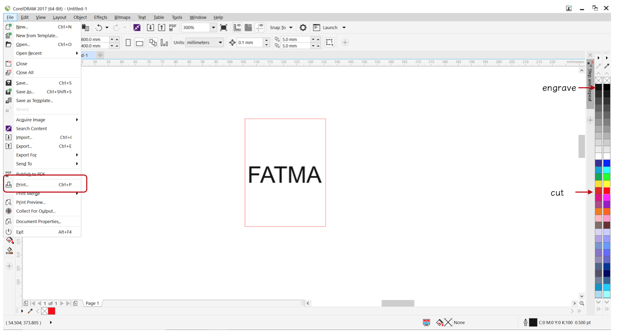
Next, click File >> Print >> Preferences >> Universal Laser systems control panel page will pop to add the setting needed for the machine.
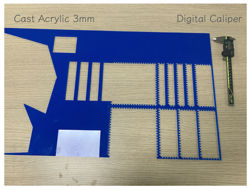
Its important to add the right thickness of material otherwise we may having errors during cutting so we measure the the thickness using Digital Caliper from all the sides and then took the average, I found it equal to 3.152 mm.
Although, the material thickness is known from the manufacturer but still we need to measure it to avoid any possible error.
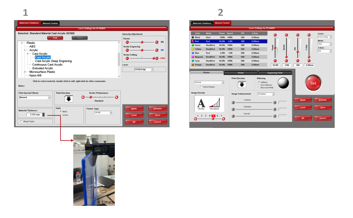
As shown above first for Material Database I select plastic >> Cast Acrylic, also I entered the material thickness 3.152 mm >> then press Apply.
(Failed )Manual control black color for engraving:
Power : 100%
Speed: 100%
PPI: 500
Manual control Red color for Cutting:
Power : 50%
Speed: 3.8%
PPI: 300
Perfect settings for (cutting and engrave) for Cast Actylic :
Manual control black color for engraving:
Power : 26%
Speed: 100%
PPI: 500
Manual control Red color for Cutting:
Power : 100%
Speed: 3.9%
PPI: 1000
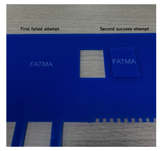
The above setting result the cutting and engraving shown below in the image it clear that the laser did not cut the board for the first attempt(failed), but the engrave was perfect so I did try one more time and I changed the material thickness to 3 mm and use the default setting for “Cast Actylic” and every thing went prefect for the cutting and engraving ,I had recode this settings in the table for future use.
The image below shown the laser cutting for the mention settings above :
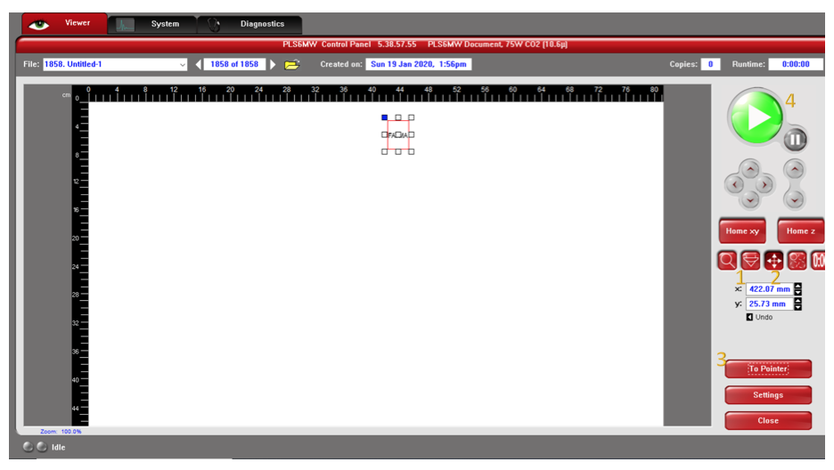
After entering all value I press “set”, then I open Universal Laser System control panel from windows toolbar.
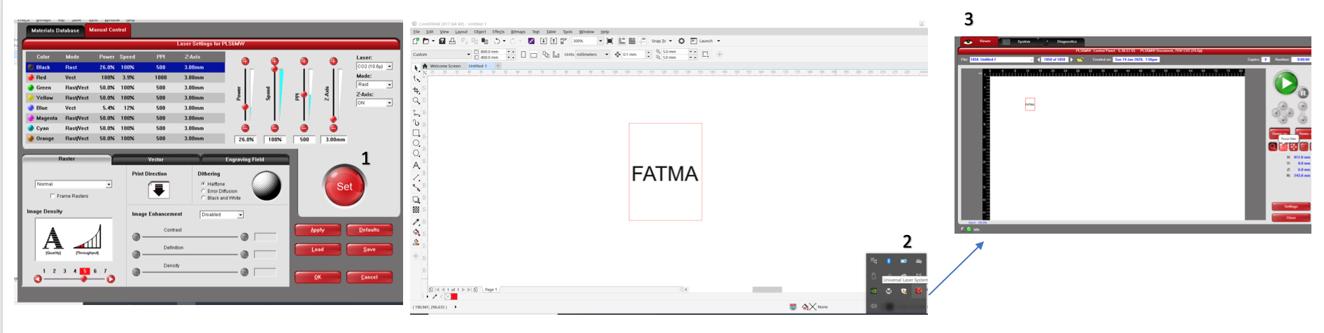
The focus in this machine is automatic we choose the “focus view” icon, then we move the design to the place we want it to be printed by using “Relocated View” then press **" To Pointer“** to put the design in place I choose then press play button to start cutting.
Kerf is the width of material that is removed by a cutting process. For the kerf calculation, Shaikha did create rectangular (60x25 mm) and section it to 12 equal parts we can have more sections, increasing the sections number will make the calculation more accurate, all of us used the same file to insure having uniform dimensions. Afterward, we used Digital Caliper to measure the length after cutting in order to find the kerf.
For the material test, I chose the MDF with thickness 3mm, using the laser machines Trotec & Universal Laser System PSL6MW.
Universal Laser System PSL6MW:
I first began by drawing in CorelDraw a simple rectangular shape with letters in the middle to be engraved. Then the border line is changed to hairline and red color while the letters to be engraved are kept in black color -After that, I selected the print option and went to the preference to specify the material and the parameters for cutting and engraving (power,speed,PPI). 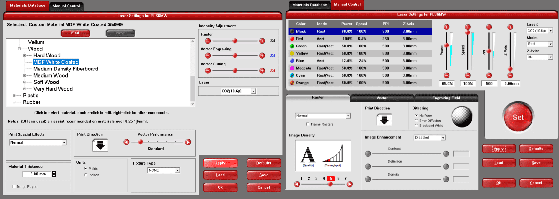
Here I kept changing different parameters every time I cut until I was able to reach the perfect result. The parameters that resulted in the best cutting/engraving are: 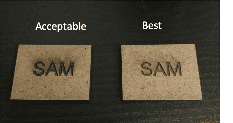
Cutting
| power | speed | frequency |
|---|---|---|
| 100% | 6.4% | 250 PPI |
Engraving
| power | speed | frequency |
|---|---|---|
| 60% | 100% | 500 PPI |
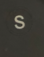
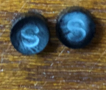
I chose acrylic as my test material. I started with universal laser machine (PSL6MW) and I drew a small circle and I add a text on the circle. I go to print >> preference >> chose the material >> change the cutting (Red color) and engraving (Black color) value as shown on the below table :
| Color | Power | Speed | PPI (Pulse per inch) |
|---|---|---|---|
| Black | 80% | 99% | 500% |
| Red | 100% | 2.5% | 1000 |
and this was the result:
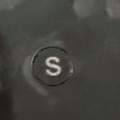
The machine didn’t cut the shape but the engraving was good so I had to change either the power or the speed of the cutting in order to cut the drawing. There is an invers relationship between the power and the speed which is mean if I reduced the speed the power will be more and if I increased the speed the power will be less. Below is the values of my second trial :
| Color | Power | Speed | PPI (Pulse per inch) |
|---|---|---|---|
| Black | 35% | 50% | 500% |
| Red | 100% | 2% | 1000 |
and this was the result :
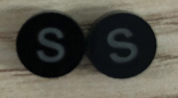
Again the same thing happened it didn’t cut. So i had to try the default setting for this materials which is shown in the table below :
| Color | Power | Speed | PPI (Pulse per inch) |
|---|---|---|---|
| Black | 50% | 100% | 500% |
| Red | 50% | 100% | 500 |
And finally it cut and this is the result:
After that i had to calculate the Kerf which is a measure of how much material is removed. It can be calculated using the following equation: (Actual length - Measured length)/Number of parts. So we draw a rectangle with a length of 60 and divided into 12 parts and we cut it using the laser machine. After that I measured the length and this was the result :
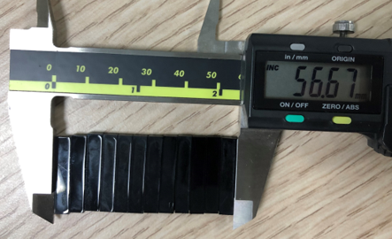
Now I will apply the equation to know the kerf of this machine:
Kerf = (60-56.67)/12= 0.27
I used the Universal laser machine (ILS12.150D) and directly I used default setting for cutting and engraving and it directly worked so I didn’t used different settings for this machine. Below are the default values for the big Universal Laser machine :
| Color | Power | Speed | PPI (Pulse per inch) |
|---|---|---|---|
| Black | 51.8% | 18% | 500% |
| Red | 100% | 2% | 1000 |
And this was the result:
And to calculate the Kerf for this machine I repeated what I did for the previous machine and this was the measured length value :
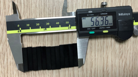
So the Kerf = (60-56.36)/12 = 0.30
Trotec:
In Coreldraw I created the same rectangular shape with letters in the middle to be engraved, again making sure that outline is hairline (red) and for engraving we keep it black.
In trotec machine, we introduce the blue color and use it along the red color for cutting in CorelDraw and that is to indicate which part will be cut first. But this feature won’t be used now since my design is straight forward.
Then using the print option, I was able to export it to TROTEC software.
In Trotec, I chose the material type and the parameters for cutting and engraving (power,speed,PPI), also specifying the process (cutting/engraving).
On the machine, I chose the starting point using the 4 arrows.
Then on the software I move the job to the location since it will be visible on software, and then click on Ready to begin cutting.
Cutting
| power | speed | frequency |
|---|---|---|
| 80% | 0.4% | 1000 HZ |
Engraving
| power | speed | frequency |
|---|---|---|
| 10% | 10% | 1000 PPI |
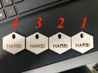
For the group assignment test I tried the setting for PPI in the laser machine (Universal Laser) on a piece of MDF that has a thickness of 3mm and started with.
What PPI mean (points per inch) determines how many dots the laser cutter head will place per inch.
1- The power of the laser is (%50) and the speed is (%1.9) PPI (%10)
2- The power of the laser is (%50) and the speed is (%1.9) PPI (%20)
3- The power of the laser is (%50) and the speed is (%1.9) PPI (%30)
4- The power of the laser is (%50) and the speed is (%1.9) PPI (%40)
5- The power of the laser is (%50) and the speed is (%1.9) PPI (%50)
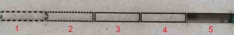
And in the picture, it shows the work of PPI as a result..
Foam is a very sensitive material to work with, specially FIS Foam the double sided foam board that is used for presentations, signs, mounting artworks or photographs. I thought that using the default Core Foam settings will be sufficient and it will not be necessary to adjust intensities of the burn, bellow was the result.
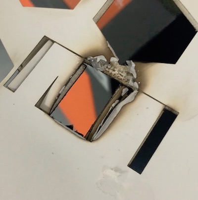
The FIS Foam bored cached on fire, good that I followed the procedure: Always Keep an eye and don’t leave the machine running. The next trial was with a less power and higher speed.
I concluded that kerf test is not applicable for foam. Due to curve nature occurring on the cut surface, measuring the pieces together is impossible and they collide with each other, and measuring a single piece gives an inaccurate result.
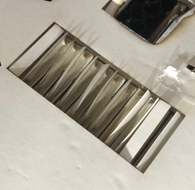
Regardless of the kerf test I still needed to find the best speed and power needed to cut and engrave on FIS Foam, so I preformed a several tests to a simple design with a cut and engrave. Using Universal Laser System ILS12.150D. The result is in the picture bellow.
| Test # | Power | Speed |
|---|---|---|
| 1 | Cut: 100% | Cut: 10% |
| engrave:50% | engrave:100% | |
| 2 | Cut: 80% | Cut: 10% |
| engrave: 45% | engrave:100% | |
| 3 | Cut: 70% | Cut: 10% |
| engrave: 45% | engrave:95% | |
| 4 | Cut: 60% | Cut: 10% |
| engrave: 40% | engrave:90% |
The best laser sitting for Universal Laser System ILS12.150D for cutting and engraving on FIS Foam would be Test # 4.
For the group assignment I selected MDf 3mm, using the universal laser cutter PLSMW.
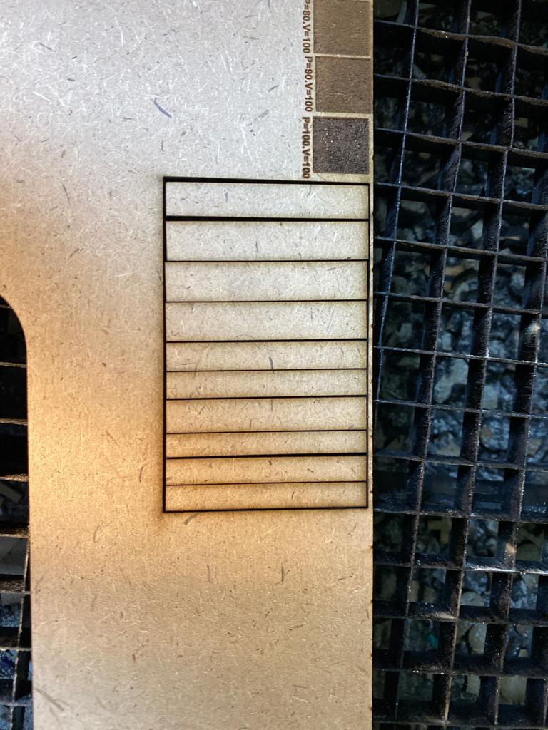
I will try to do several engraving test with varying the power and fixing the frequency to be 250 PPI and speed to be 100,
to do that I have to draw a rectangle using coreldraw software then going to File >> Print >> Preferences >> Universal Laser systems control panel page will pop to add the setting needed for the machine.
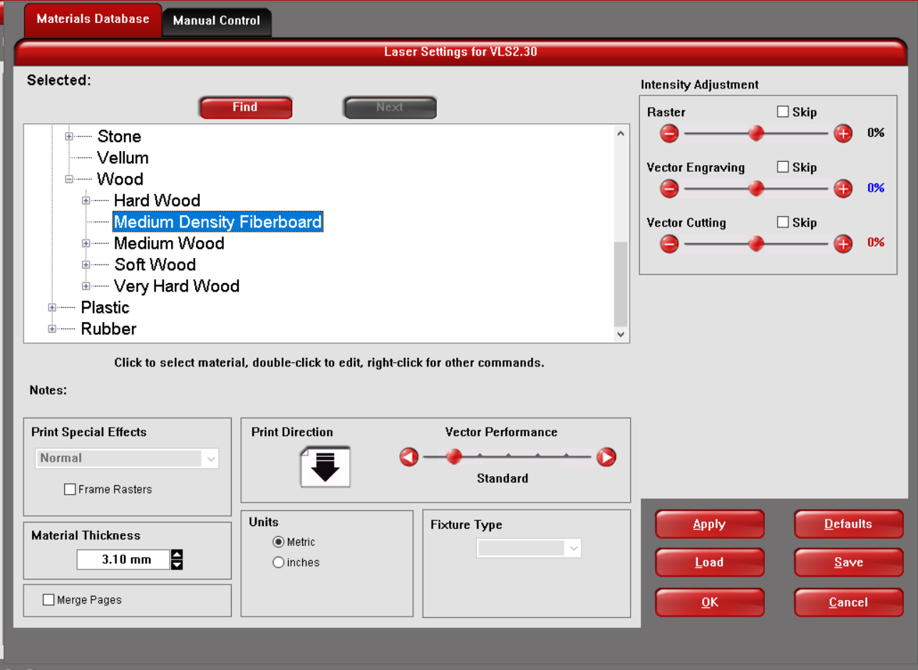
Fisrt thing to do is to select the material go to Natural >> wood >> Medium Density Fiberboard ,
and modifying the material thickness according to the sheet you have in my case it was 3.1mm
after that under the manual control tab to adjust the power and speed according to each test,
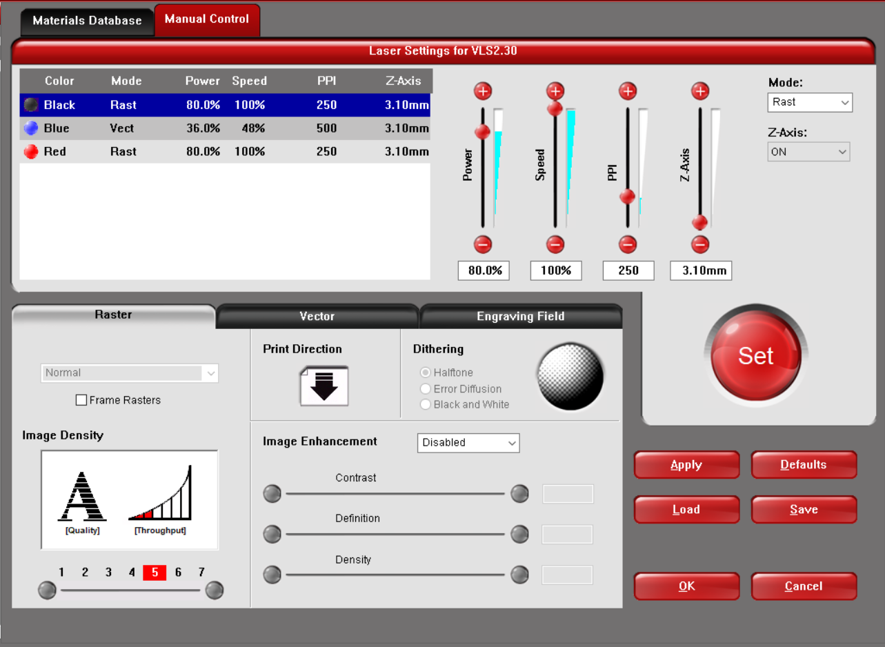
and then I just ran the job
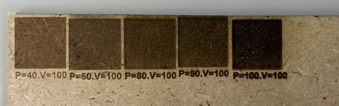
you could easily observe the difference in each test, where it gets darker when the power in increased.
to calculate the kerf I draw a rectangle with legth of 80mm by 30mm then devided into 10 pieces, then I cut it with the universal laser cutter PLSMW
I found that measuring the pieces together was only 77.34mm
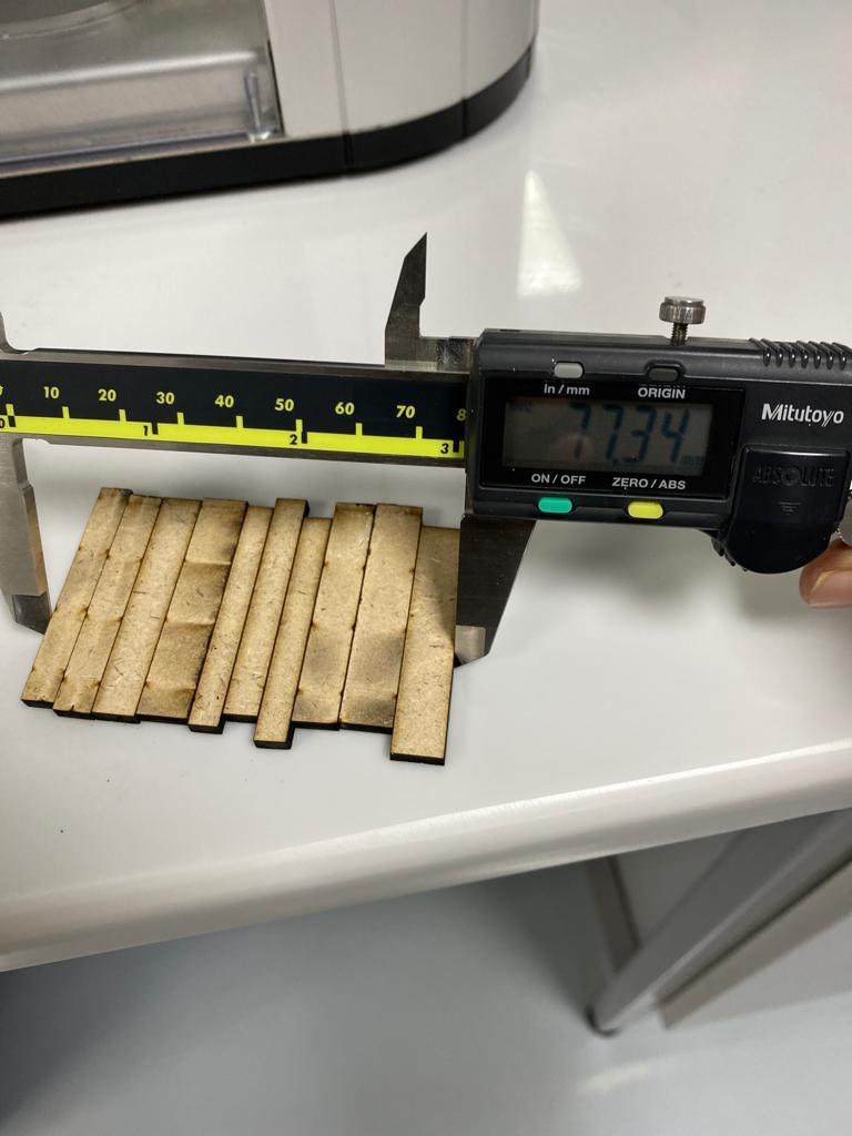
to measure the kerf we simply use the following equation: (Actual length - Measured length)/Number of cuts.
Kerf = (80-77.34)/11= 0.24