This week’s group assignment goal was the following:
Characterize the design rules for the PCB production process
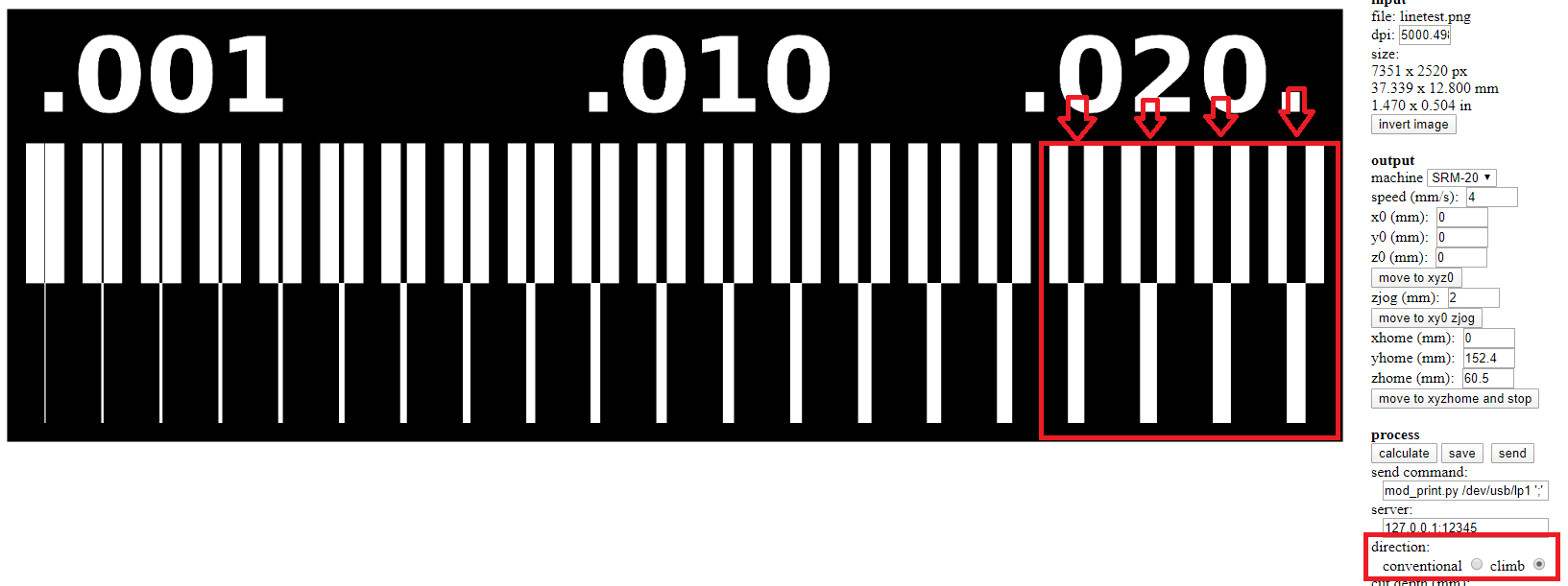
I have a group assignment that I have to make so my instructor gave me this assignment. I opened this website and inserted my trace to use it.
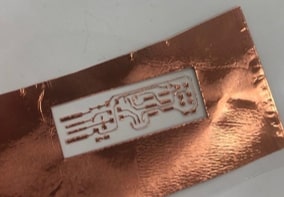
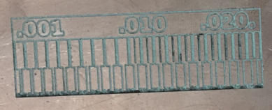
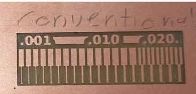
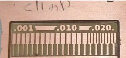
The picture above shows the traces of my assignment.
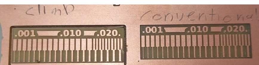
I used 1/64” (0.4 mm) milling bit on two pictures and the direction I used is ‘’Climb’’ and then I used ‘’Conventional’’ for each one.
I do not see any change from these settings Climb and Conventional while engraving. The machine engraved the first four parts of the circuit and I might use a laser machine to complete it.
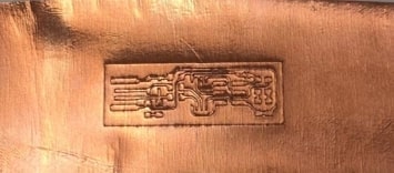
This picture shows where the machine engraved the board. It engraved only 4 parts only and the others I couldn’t.
In this week we tested the capabilities of the vinyl machine to produce an ISP PCB. Since all of the students wanted to try the vinyl machine, we decided to test for the perfect settings.
The first thing we did was to place the copper sheet on a double sided tape, then place the whole thing on a transparent transfer paper. This steps ensures that the copper sheet has some stability for the cut.
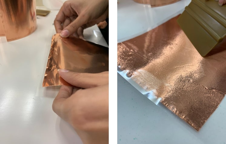
Next, we inserted the sheet into the vinyl machine, choosing piece instead of roll this time. This option allows the machine to take measurements of the height and the width of the piece we are choosing.
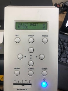
While still to use the copper sheet sparingly, try to using a bigger sheet of the transfer paper, or else the machine wont be able to detect the parameters of the sheet, and display the error message sheet unloaded.
Next we followed the same steps of using CoralDraw to change the traces to vector, then place in RolandCut studio software that would connect us to the machine. In this step, Instead of entering the length of our choice in the cutting setup, we entered the parameters measured by the vinyl machine.
Another point to be aware of, was the placement of the vector image in the RolandCut Studio, hence the negative space caused by the placement of the motors needed to be considered.
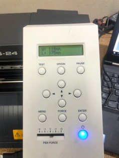
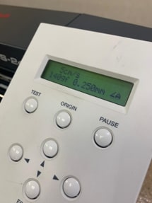
Ahead of cutting the PCB, we tested for the best force, and found out that using a range of 140~150% produced the best cut.
The results of the cut were not as satisfactory as expected. The copper sheet was extremely fragile, the traces were very thin, and moved off the double sided tape even before we started weeding. While weeding, the traces were cut off easily due to being so thin. So we aborted this process.
For our second trial with the vinyl cutter, we skipped the double sided tape adhering the copper sheet directly to the transparent transfer paper. And re-did the steps above.
The results this time could be only be described as .. better .. compared to the results of our previous attempt. The traces were much more stable and adhered better to the transfer paper. However, the traces were still to thin and hard to handle and some broke off while weeding.
While discussing this issue with our instructor, we came to a conclusion that the conversion of raster to vector images in CoralDraw may have “eaten” some of the width of the traces away causing them to be too thin.
A couple of suggestions to solve this issues popped out. We discussed the possibility of re-doing the PCB on eagle, and changing the width of the traces, or the possibility of somehow skipping the CoralDraw step and using another tool to turn the raster picture into a vector.
And thereby, we went with the easier solution first. We referred to a tutorial to learn how to import an image directly into Roland cut studio.
The image needs to be in A jpg format, thus we used the PNG to JPG web tool for the conversion. Then the image can be imported directly by clicking on the import tool.
A problem we faced while doing this is the size of the image, as it appeared to be scaled up. To solve this issue we uploaded the image into fab modules to check for the exact dimensions in inches, and scaled the image in cut studio accordingly.
The image now is still raster, so we used the bitmap tool to trace the outlines and change it to vector.
We re-entered the parameters of the piece we were using and it was time to cut.
The results this time were astonishing! The cut was extremely neat and the traces were visible and bold. Much better than the previous attempts.
 Next, we mass produced the flexible PCBs for our team. And everyone moved on to their individual tasks of weeding, soldering and programming the ISP.
The time-lapse video below shows the procedure of fabricating PCBs :
Used machine: Trotec speedy 400 flexx laser
We would like to produce PCB using a fiber laser, therefore we decided to work in a group to test the limitation of the machine that will give us the best settings for the traces and pads.
The steps are as follows:
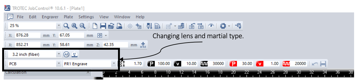
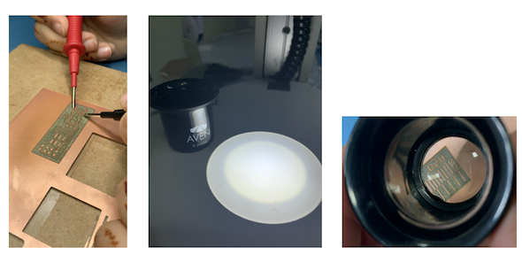
because we need engrave copper which is a reflective material that needs fiber laser. As shown in the image below the **fiber 3.2“** lens with manual focus tool.
While changing the lens we must be really careful to not cause damages in the lens or broke it as it’s so expensive and sensitive can be easily broken.
Moreover, there is no store in Dubai provide the lens so if we lose it we need to order online and it takes a long process as our instructor mentioned.
The video below shows the process of changing the lens:
Also we need to select the lens type in the software.
Making sure of the leveling is very important as we did with milling, inaccurate leveling may cause problems in focus which leads to cause problems in cutting.
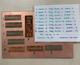
The below Table shows all the test settings until we reached to the best setting:
| Speed | Frequency (Hz) | Passes | Position | |
|---|---|---|---|---|
| 1 | 7 | 20000 | 6 | Top Left |
| 2 | 7 | 20000 | 10 | Top Left |
| 3 | 5 | 20000 | 10 | Top Left |
| 4 | 5 | 20000 | 12 | Top Left |
| 5 | 10 | 30000 | 4 | Top Left |
| 6 | 10 | 30000 | 4 | Top Right |
| 7 | 10 | 30000 | 4 | Top Right |
Best settings we come with so far:
| Speed | Frequency (Hz) | passes | position | |
|---|---|---|---|---|
| 8 | 10 | 30000 | 10 | Top Right |
Observations :
We notice big difference if we changed the position from Top left to Top right as recommend in this guide made by one fab academy instructors, we did use the same settings in the top left and top right and get different results shown in trial 5 and 6.
Sometimes after cutting by laser everything looks good but the problem there will be small particles of copper cant be see with naked eyes, we need to use a magnifier or do connectivity tests to know that there’s a short circuit.
The steps below are a summary of the cutting steps, for more details visit Maha page:
Changing the lens from fiber to Co2, fiber laser used for engraving copper it will not be able to cut it.
Open the PCB outline image in CoralDraw.
Load the cutting settings in the software suggested from this guide as shown in the table:
| Power | Speed | Frequency (Hz) | Passes | Correction factor |
|---|---|---|---|---|
| 60% | 5 | 1000 | 10 | 15% |
Observations:
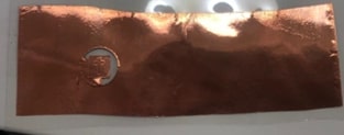
As shown in the image above the copper sheet with our trial using the above settings,
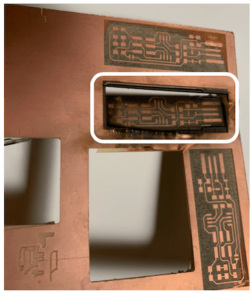
it’s clear that the outline did not cut completely, the problem was from leveling the copper sheet on the board, not from the settings, consequently, its important to align and fix the FR1 sheet at the board very well, another important point we forgot about is to keep the reference point of the laser after engraving without moving it, since it will be difficult then to return it to the correct place and traces may get damage by mistake. Moreover, fabricating PCB using the fiber laser consumes a lot of time more than using other production techniques, and need high precision while working.
Open the Mods page and follow the tutorial mentioned in the fab academy page.
Right click on the page and chose program
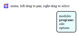
open server program
Roland mill (SRM 20) so I chose it as shown below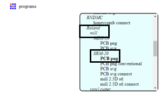
png file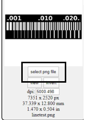
mill traces (1/64)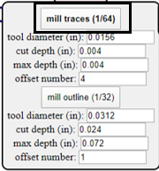
0.2 mm then clicked calculate and the below picture will appear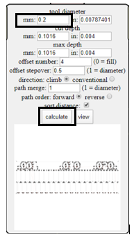
delete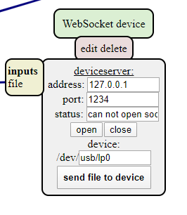
modules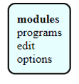
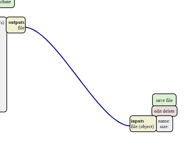
I recalculated the process and then the file will be saved automatically on my computer.
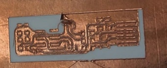
I fixed the xyz points on the roland machine and make sure they are in the right place after that I entered the file and clicked on cut to start the milling process and what happened is when the machine start working it goes up or to be more specific it goes somewhere not the xyz points that I chose so it started milling on the air. At the beginning I thought that I miss a step or I did something wrong so I tried to print it again but the same problem occurs so I asked for help from our instructor and again the same problem happened. So he told me to try to use fab modules instead of mods so when I follow the fab modules steps it worked and the machine work perfectly and this was the result of using the 0.2 mm milling pits:
I have a group assignment what the defrent between Climb Milling and Conventional Milling instructor gave me this assignment. I milling two pieces to see the difference between them

but i couldn’t see a difference between Conventional Milling and Climb Milling. But I read on the web site and understood what the difference is
The Conventional Milling: Starts cutting from zero and increases which cause more heat on the material to cut it. The speed of the machine increases as it cuts. Used for hard materials like stainless steel and steel.
The Climb Milling: Starts cutting at maximum speed and then decreases. Creates cleaner surfaces. Used for making clear adjustments for a better surface finish after cutting the material.