Input Devices Group Assignment
In this group assignment we are going to probe an input device's analog levels and digital signals.
Analog levels
We measured the analog levels of an LDR:
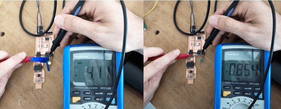
You can see how the voltage at the analog-input-pin changes between 0,8 and 4,11V depending on the amount of light that hits the LDR.
Digital signals
For the digital signals we decided to measure the Humidity sensor DHT11 (datasheet)
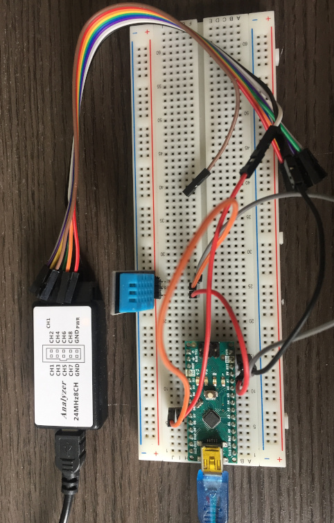
We used a cheap Logic Analyzer 25MHz8CH with the software from Salae.
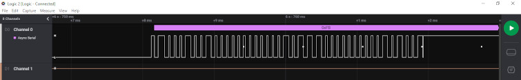
After installing the adafruit-library for the DHT11 and uploading a sample sketch, we were able to read the digital signals on the output pin of the DHT11.
We also did a test where we measured the "TX" output of the Arduino while sending the letter "1" from the Arduino serial monitor.
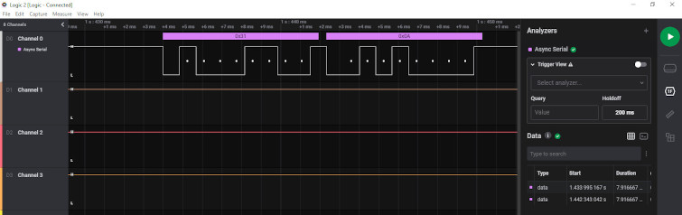
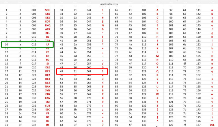
In the data we measured with the Logic Analyzer you can see the letter "1" (0x31) and the Linefeed (0x0A).
Probing the Sonar
Before doing the test I made a quick research cause I didn’t really know what and how I was supposed to probe 😅, then I found a good explanation of the sonar sensors:
Image taken from Last Minute Engineers
In this case I wanted to watch and compare the behavior of Trigger and Echo sensor.
I made the test connecting the Echo pin to Channel A (in yellow), and the Trigger pin to Channel B (in green):
Description:
According to the code uploaded to the board:
- The Trigger sensor produces the 10 µS pulse (the green signal in the oscilloscope) every 100 microseconds.
- The Echo sensor uses the width of the received pulse (the yellow signal in the oscilloscope) to then calculate the distance to the reflected object (my hand in this case).
Probing the Joystick
I did the test connecting the X pin to Channel A: