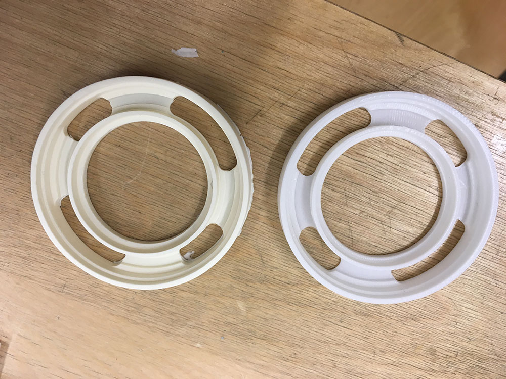
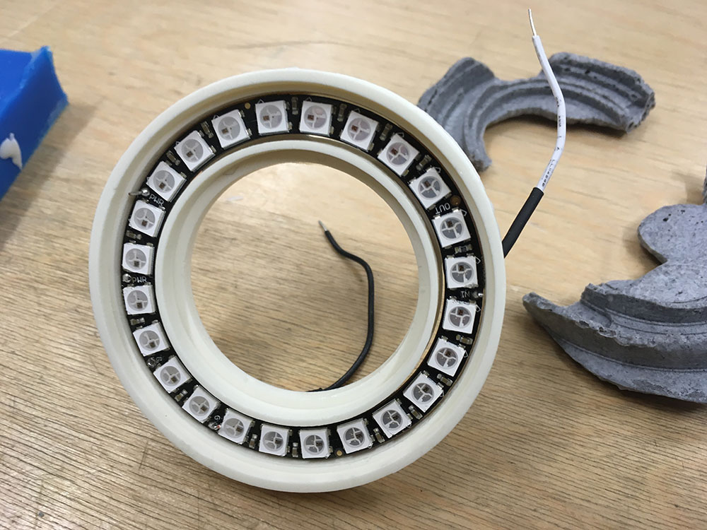
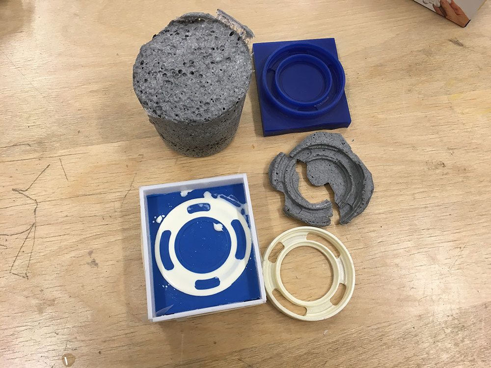
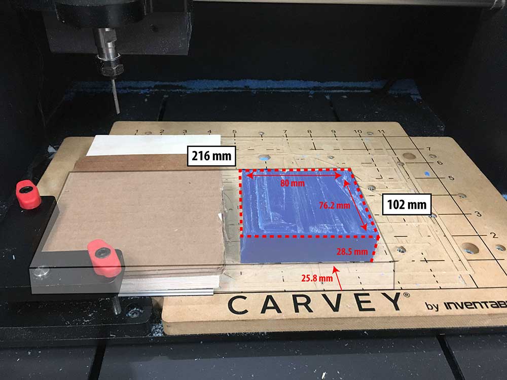
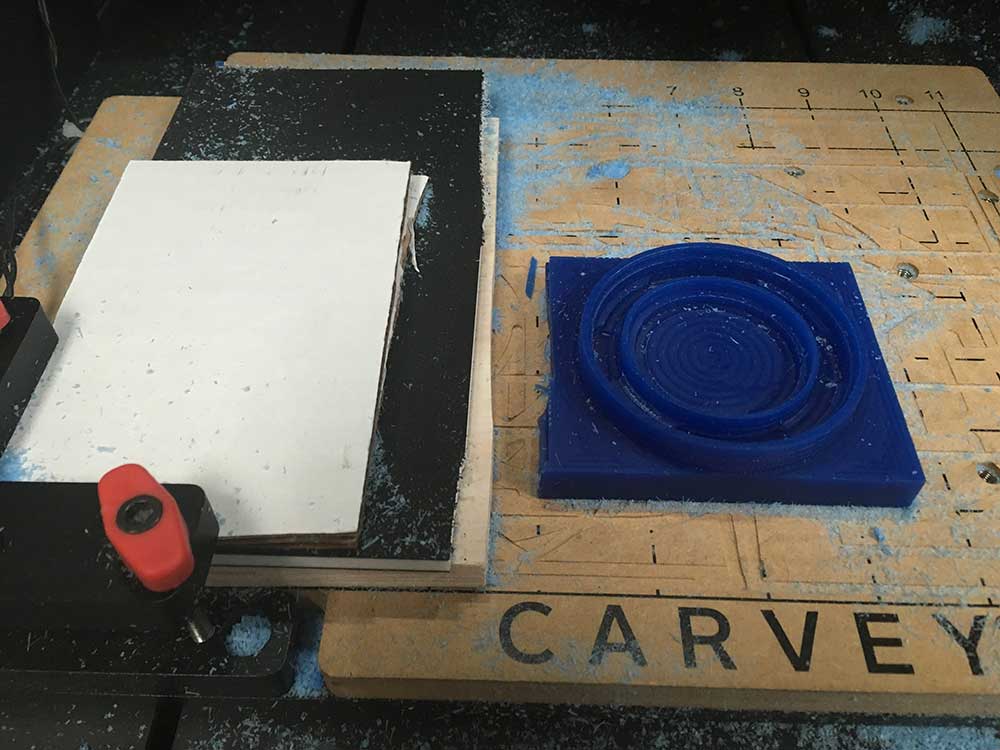
I was excited to dig into 3d milling and to learn more about Fusion 360's compatibility with the Carvey mill. Once I had my model created, I had to prepare the tool paths for milling. The clamp on the Carvey can take up a lot of space and everything is milled in relation to it. On other machines, like the Roland series, you can manually position your milling bit and set the origin of the x,y,z accordingly. With the Carvey, everything starts at the clamp. This proved to be a bit of a problem as there would never be enough space and material to mill my model near the smart clamp. Also, as I made mistakes I had to work with smaller pieces of wax. The smart clamp took up to much space and I had to find ways to "trick" the machine.
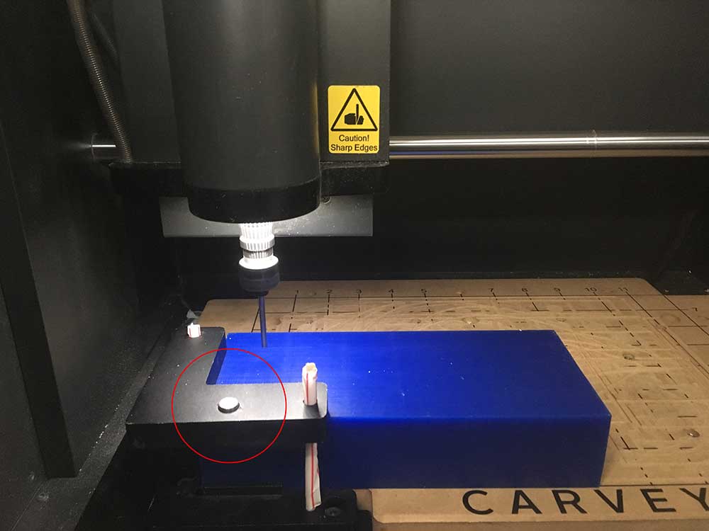
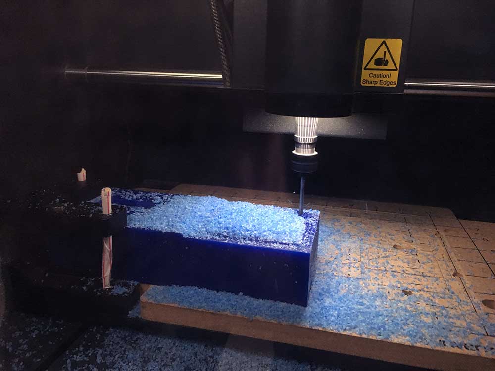
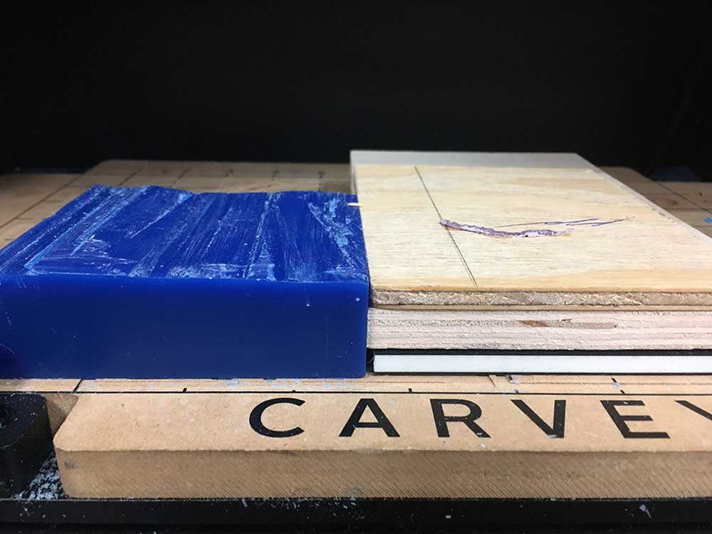
Note:If you are looking at this picture and wondering why I had the straws in there, it is because the Carvey does not come with bolts for stock thicker than 1". The material is secured using double-sided tape so I only needed the clamp for homing purposes. I had to use dowel, straw, and more double sided tape to secure it in place. I later received a gift from my Fab Academy colleague Mark which was the right sized M5 1.5" bolt. This "jerry-rigged" setup worked but I don't recommend it. Inventables sells larger bolts or pick up your own M5 bolts at the hardware store. They are not as common in generic hardware stores in Canada and I was unable to get one the day I worked on this assignment.
Before starting to program all my tool paths, I visited a variety of forums and sites to figure out what the optimal speeds and feeds were for milling wax and also for milling wax on the Carvey. Here are the links I visited:
---> Machineable Wax - Technical Info
---> Inventables - Machineable Wax
---> Autodesk - Feed Rates
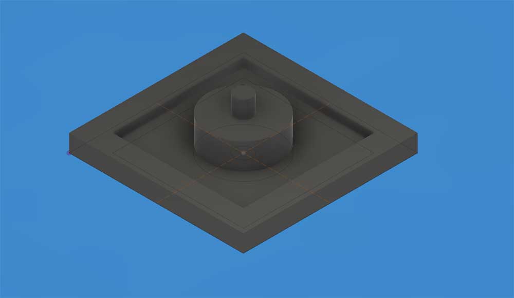
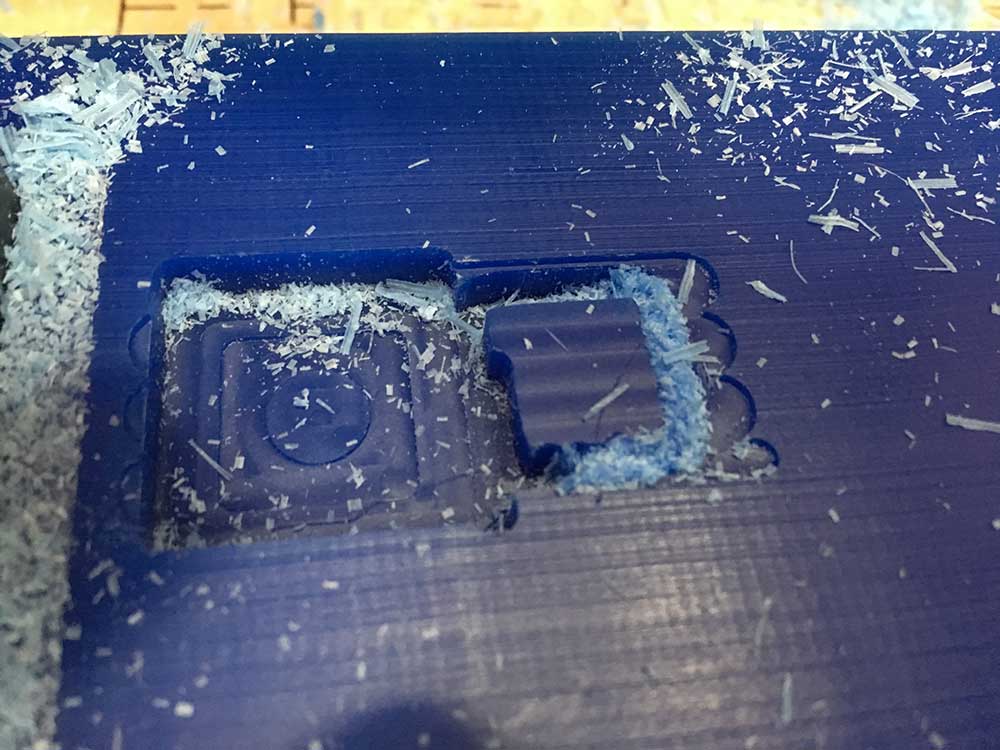
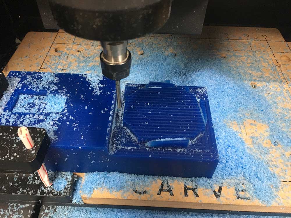
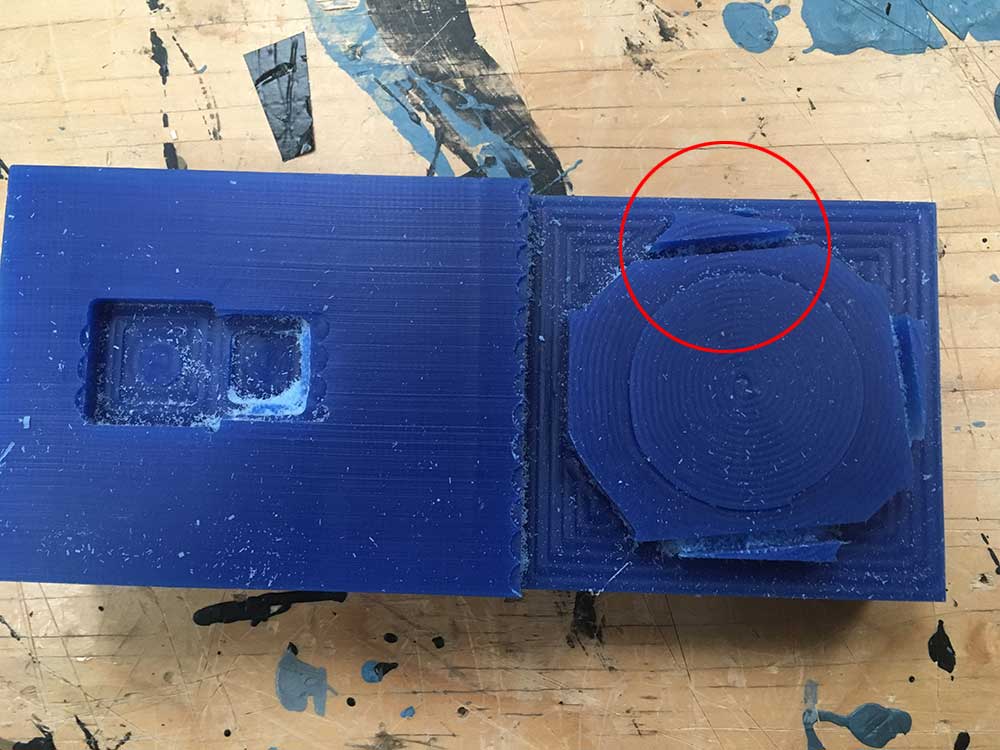
Before milling my part, I decided to attempt a quick test to check the workflow and test the Carvey post processor. I modeled a small shape and sent it through. I won't go into detail but I was happy that I successfully milled the wax. However, when it completed I realized that my tool path was wrong.
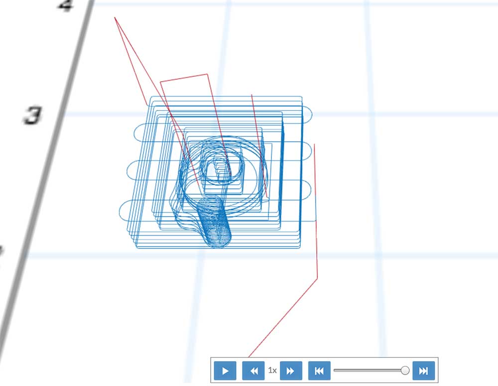
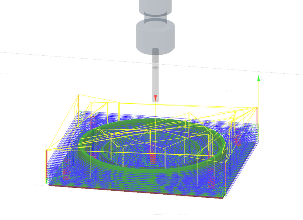
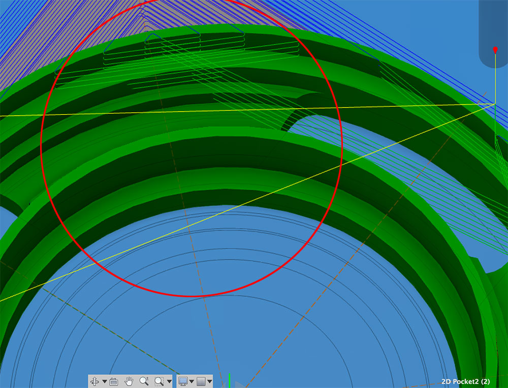
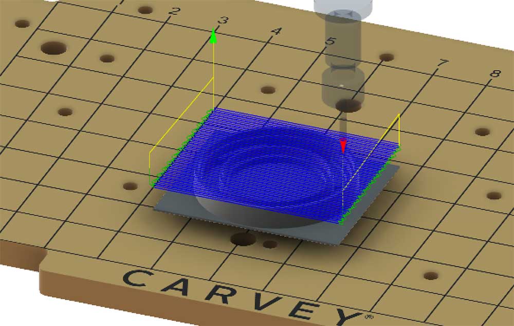
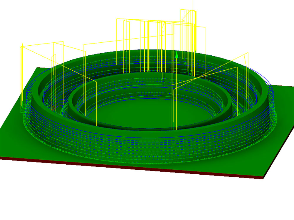
As you can see, I milled through the pin that was in the model. If you look at the image above of the tool path, you can see it spiraling down through the portion of the pin. The boundary geometry for that small pin in the middle of the model was not clearly defined when I sent over the job.
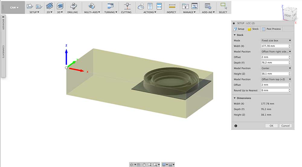
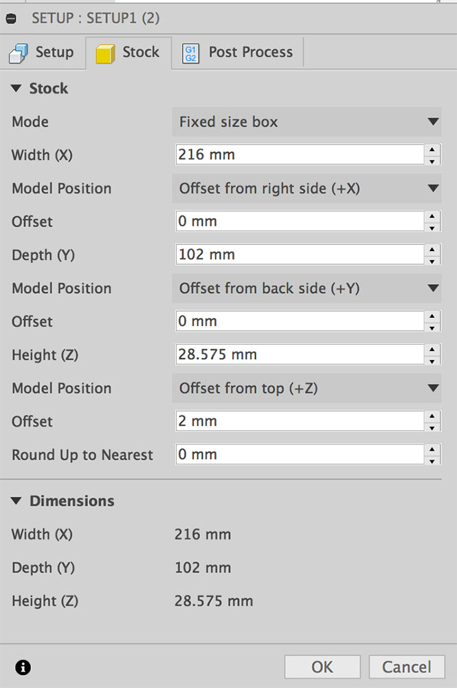
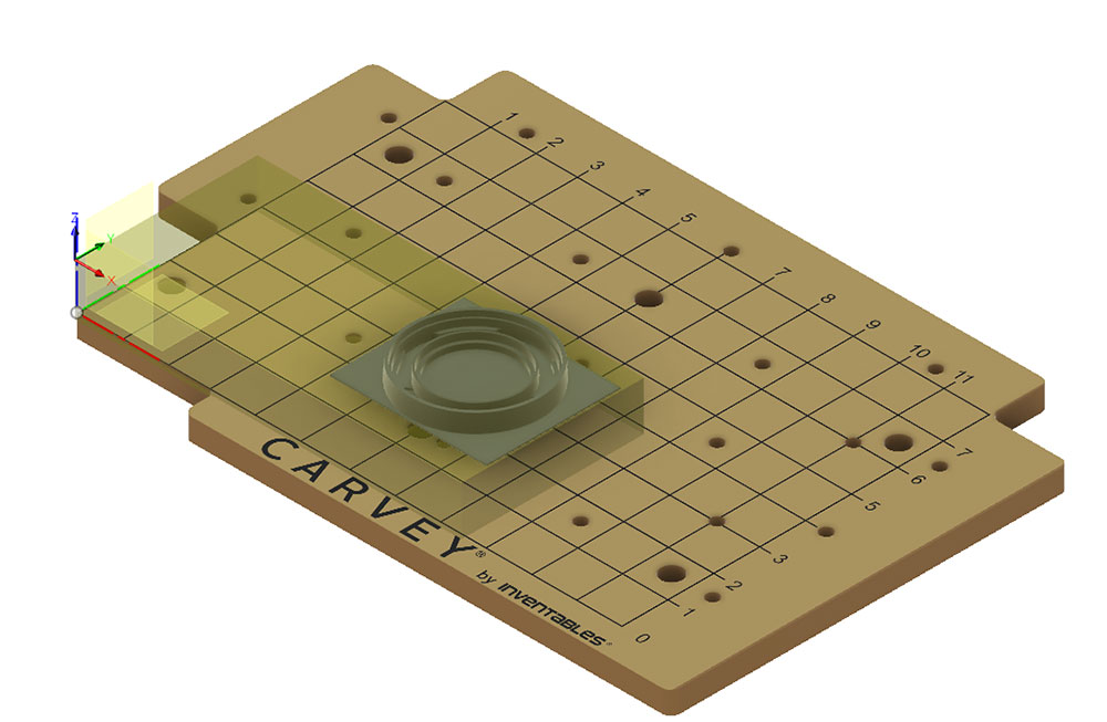
After the quick test, I started prepping for the milling of my model. First I set the dimensions of the stock I was going to use and the position of the model within that stock. I had a piece of milling wax that was 7" (177.78mm) wide, 3" (76.2mm) deep, 1.5" high. I left a 2 mm offset from the top of the stock as well as a 2 mm offset from the right side of the stock and I positioned the model in the center of y. I have very little room on the y axis so centering just ensured that the piece fit within the stock.
Next I made sure the orientation was set to Box Point and that the origin was at the top of the material in the bottom left corner. Because of the Carvey's smart clamp the origin is set at the surface of the stock that is under the clamp.
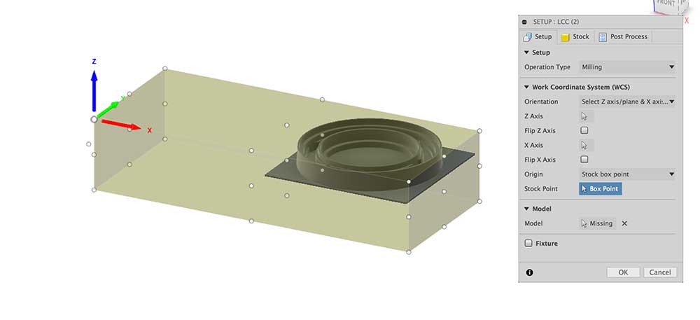
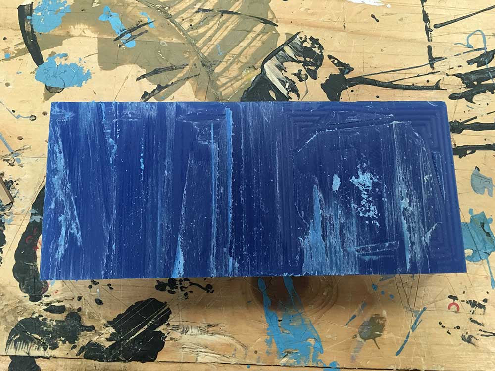
Once the stock settings were set, I needed to program the first tool path which was to re-face the surface of the wax. Although I was using a new piece of milling wax with a smooth surface, this step ensures that the surface of the stock is precisely located where the gcode expects it to be. It will help reduce any discrepencies. The fact that my clamping mechanism was not as precise as it would be with the right bolts, this step was even more relevant. It meant I could mill the wax to the right depth before starting to cut the geometries of my model.
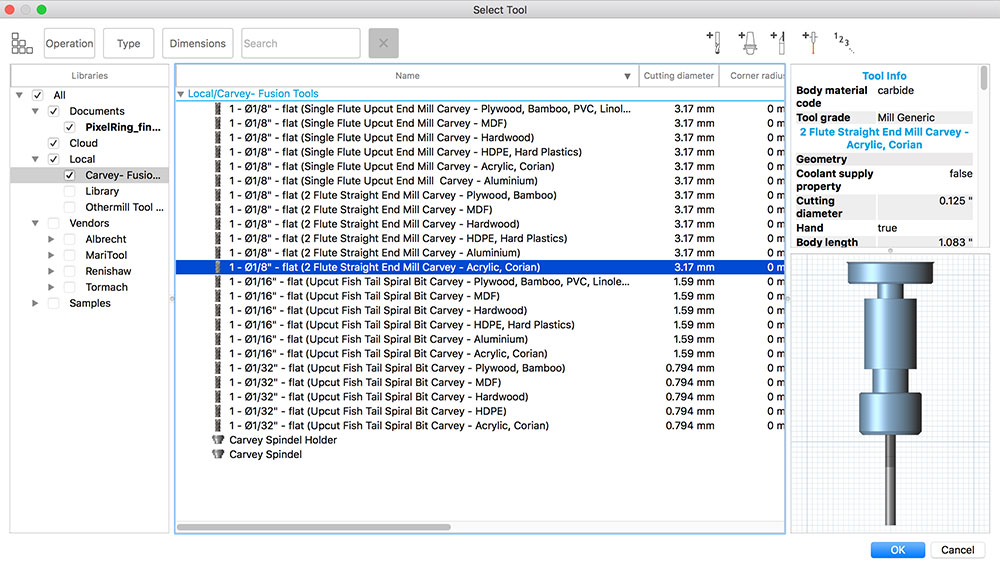
The first setting was to choose the right tool. I used only one tool for this entire milling process.
---> 2 Flute Straignt End Mill
To learn how to import a tool library into Fusion I visited the following:
---> Importing a tool library
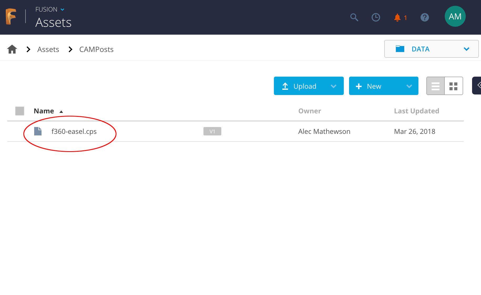
---> Carvey - Fusion Tools
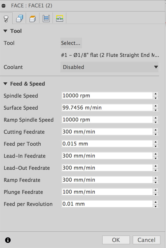
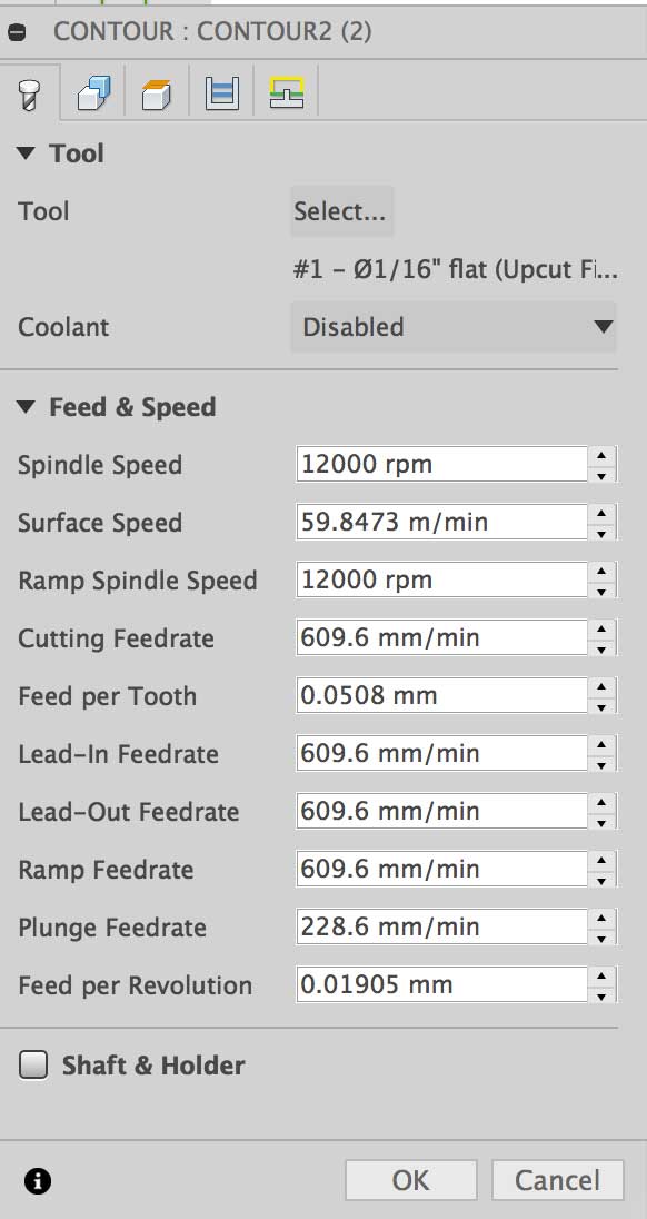
After the stock setup, I selected the feed and speed settings. Generally speaking, keeping the spindle at 10000 rpm for finishing or facing was fine.
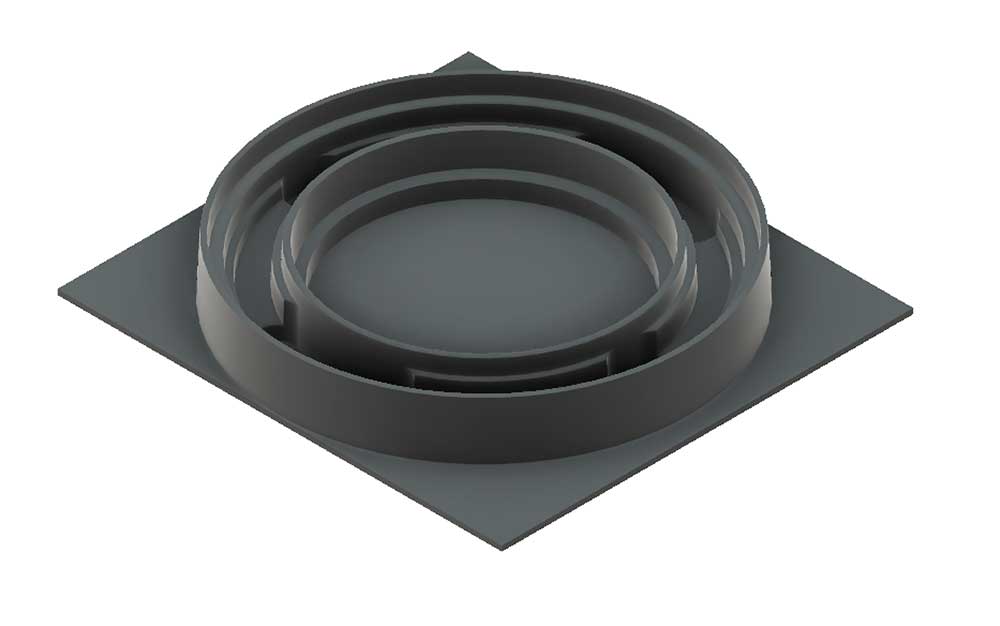
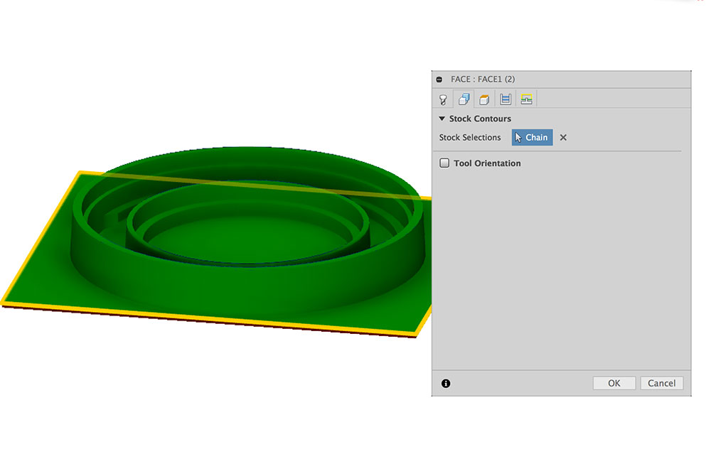
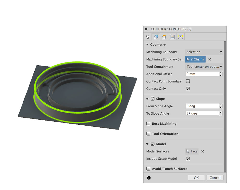
I made my model with a square base thinking it would help to create a perimeter around it. I selected this base as a boundary for the geometry. This worked out well.
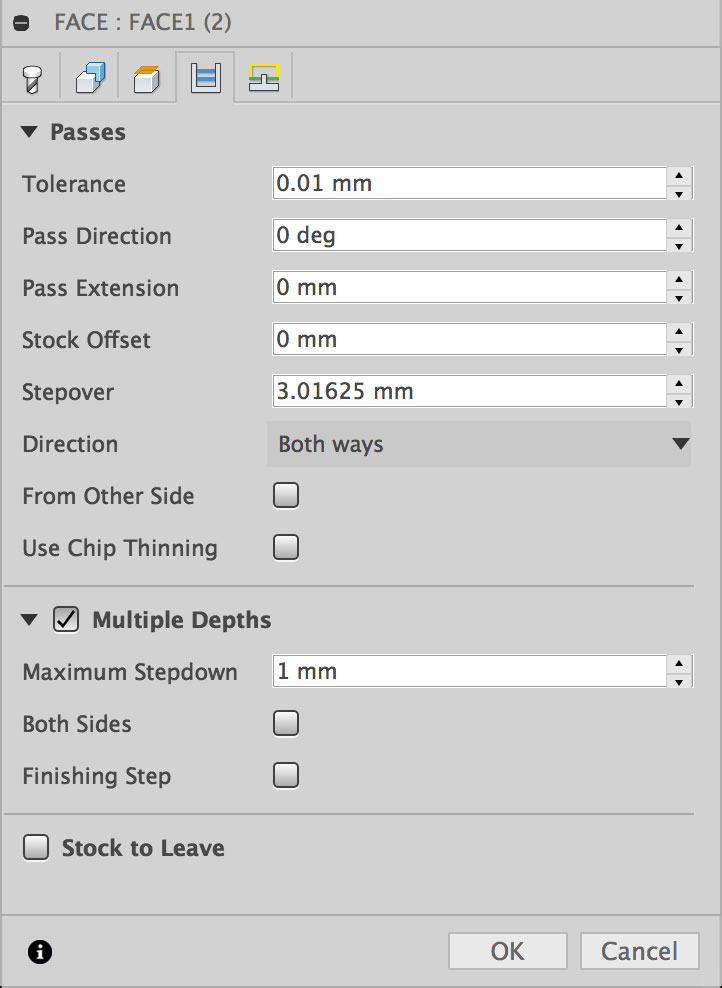
Next I selected the depth per pass by enabling Multiple Depths and selecting it to mill in increments of 1 mm.
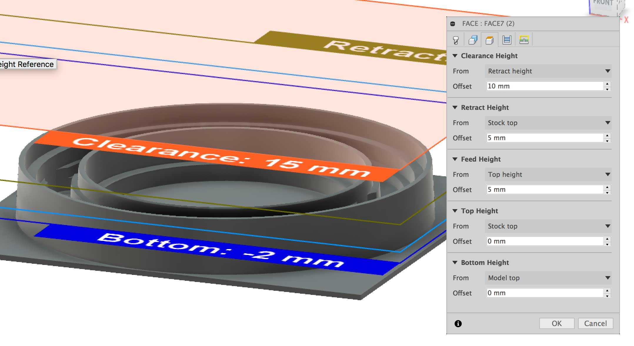
Lastly, I selected the Bottom Height to equal "Model top" and the Top Height to be "Stock top". You will notice Bottom:-2 mm which is the model offset that I had entered in the initial stock setup.
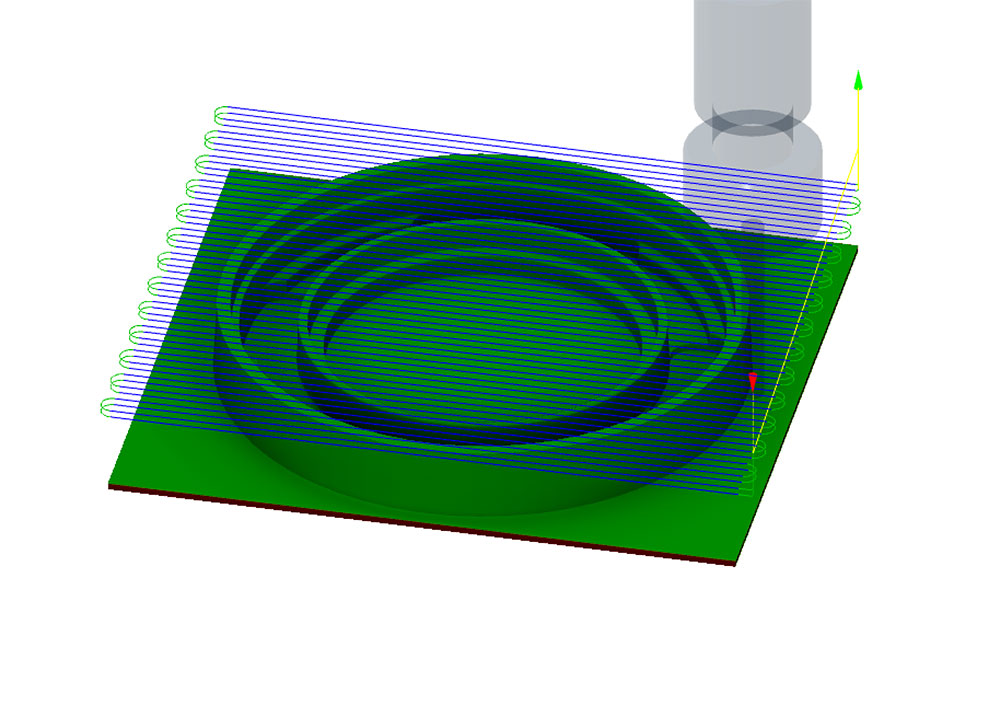
After applying the simulation, the Facing operation looks good.
This process went well.
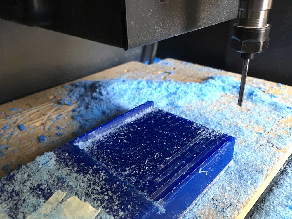
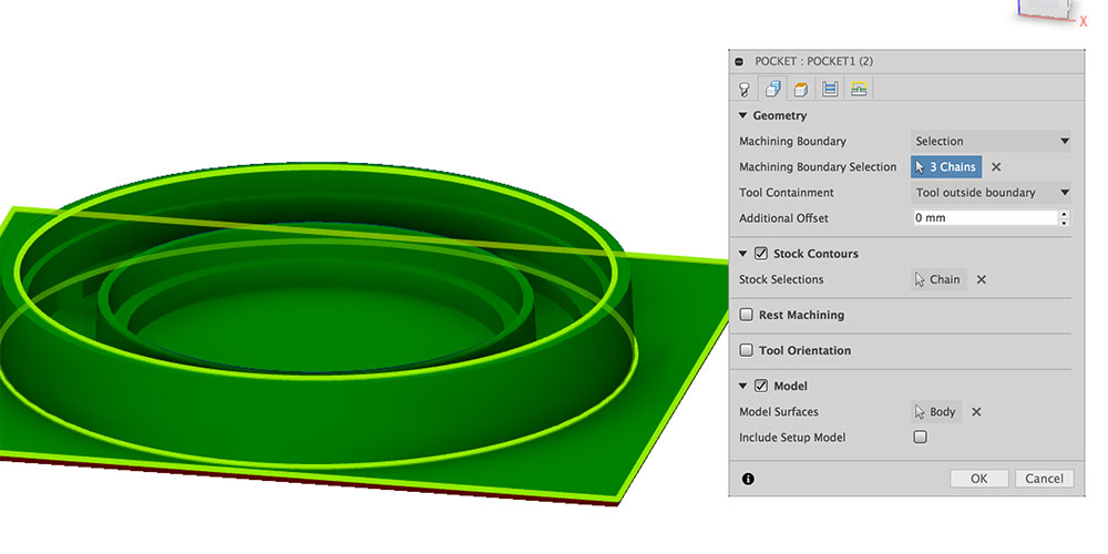
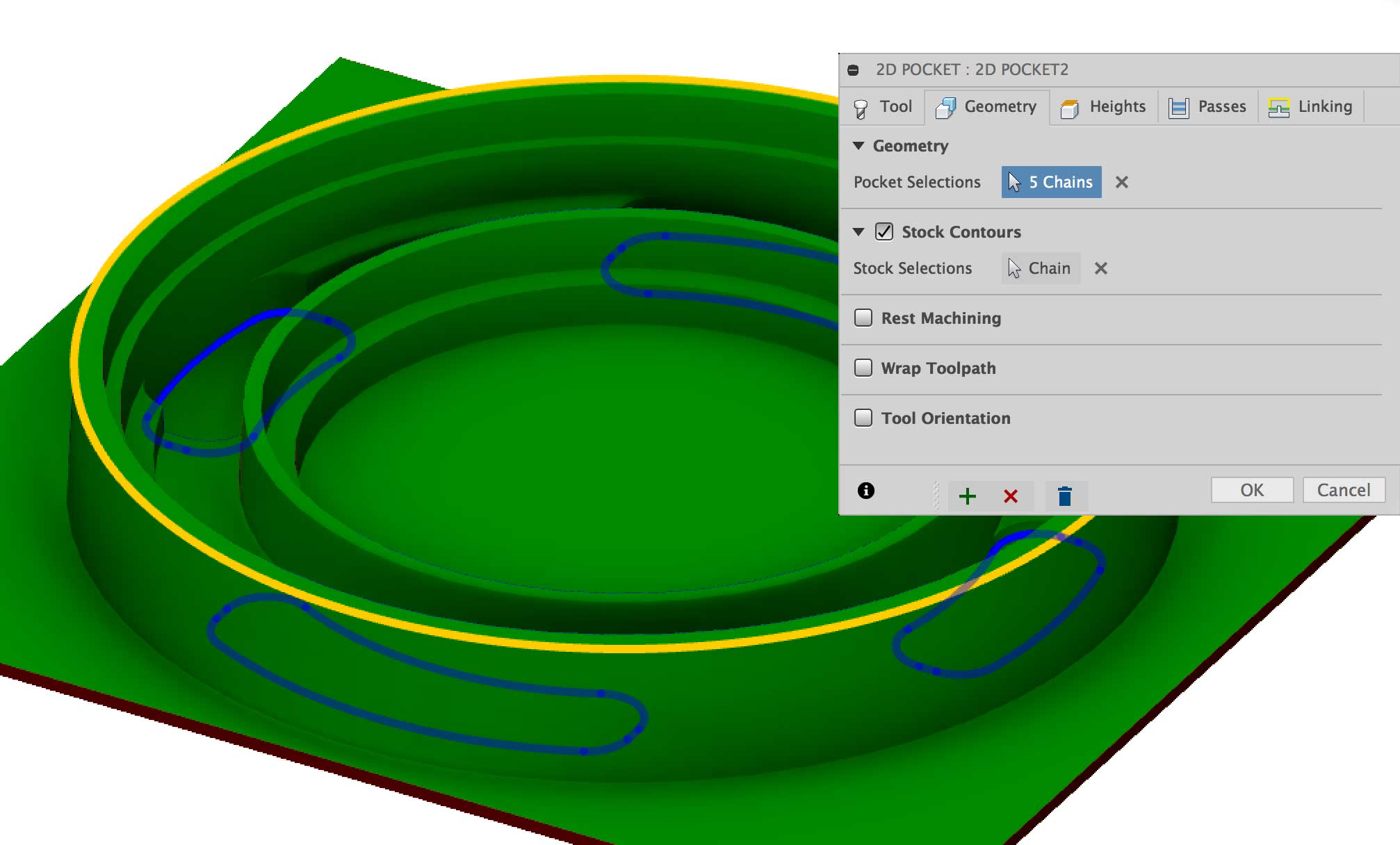
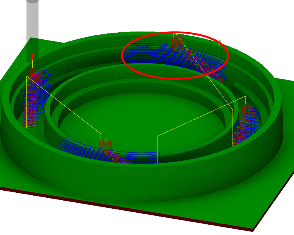
Next process was to rough out the caveties of the the model through 2D pocket clearing. I selected what I thought were the right geometries but as it turned out, I was wrong. The tool path I had selected cut through the model so I stoped the process.
I removed a layer of wax using a saw and prepared to try the process again.
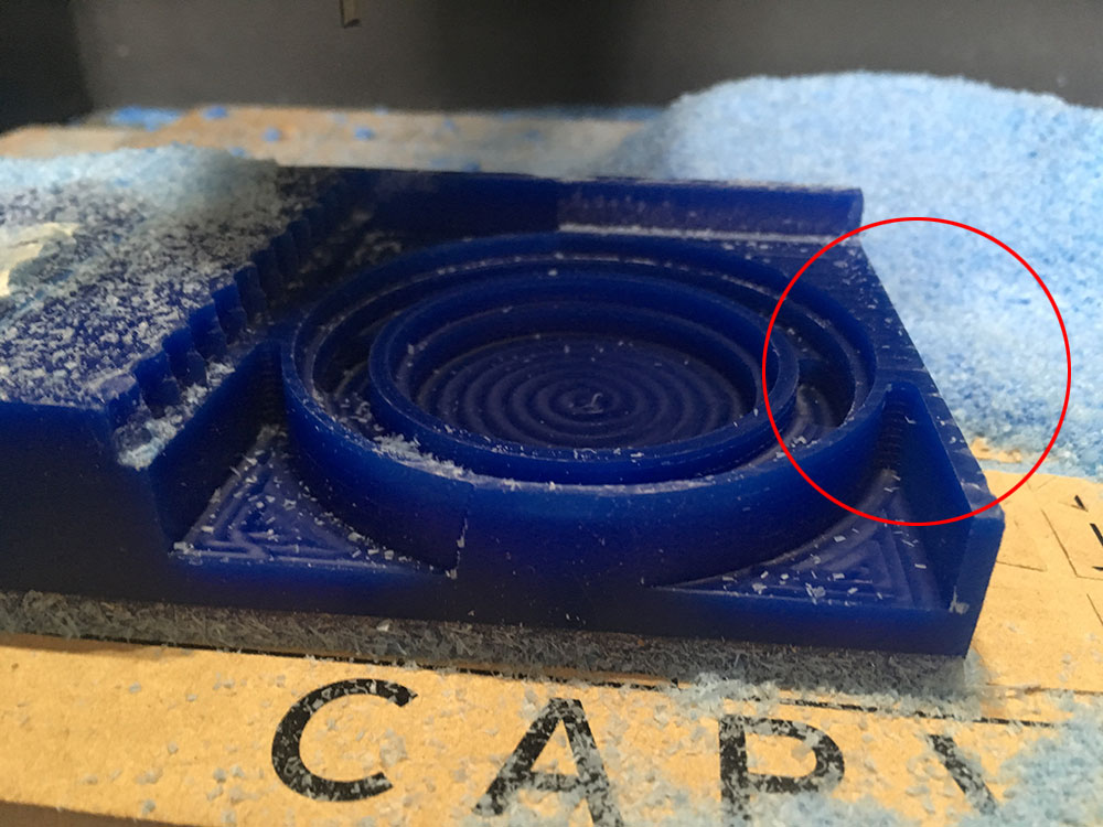
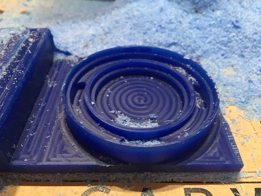
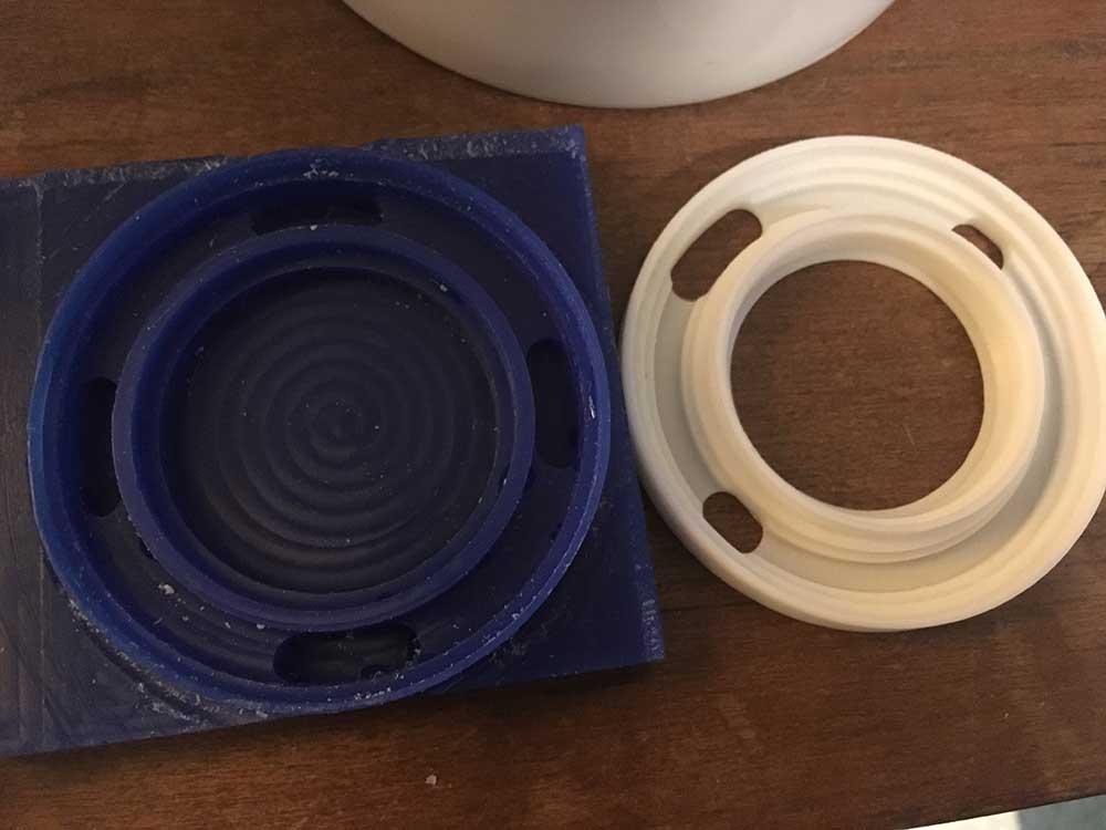
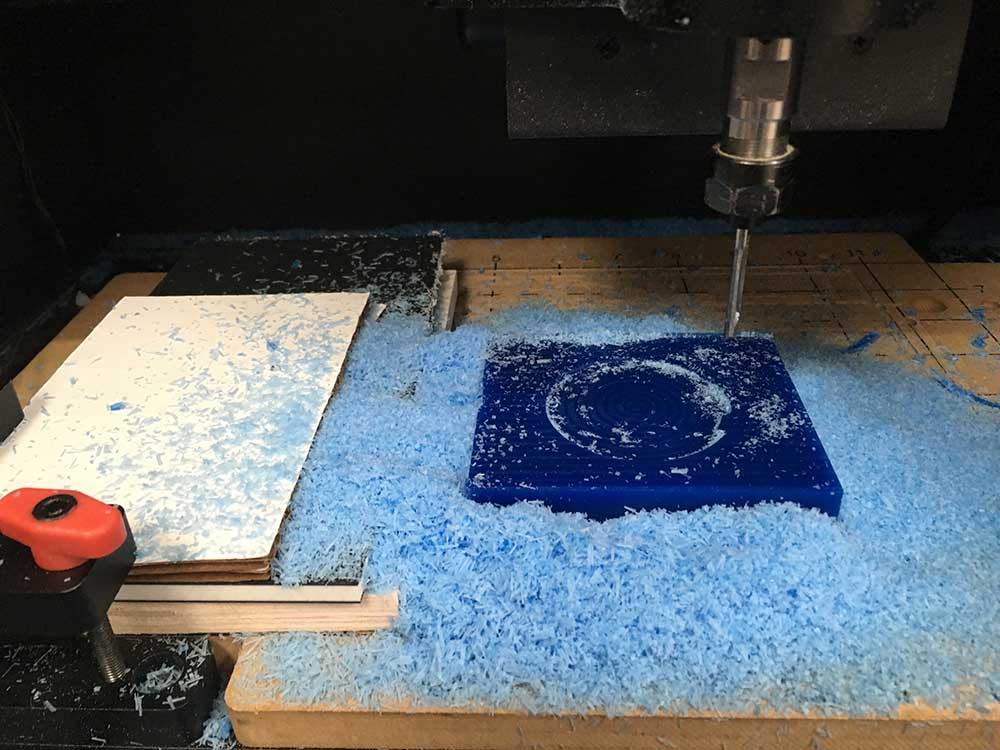
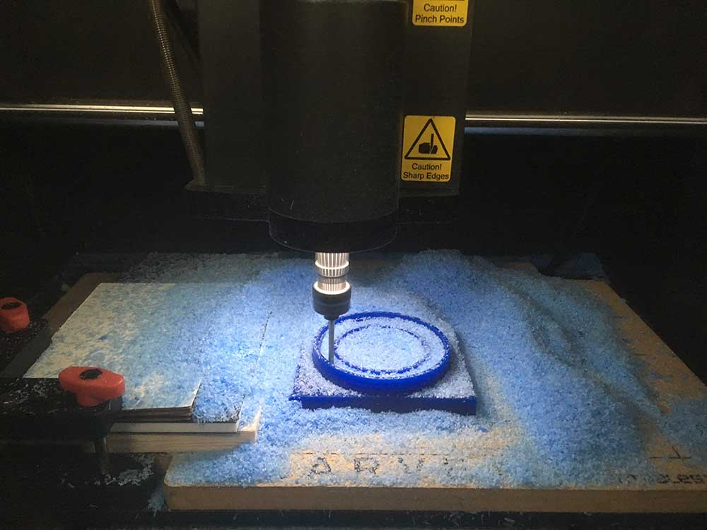
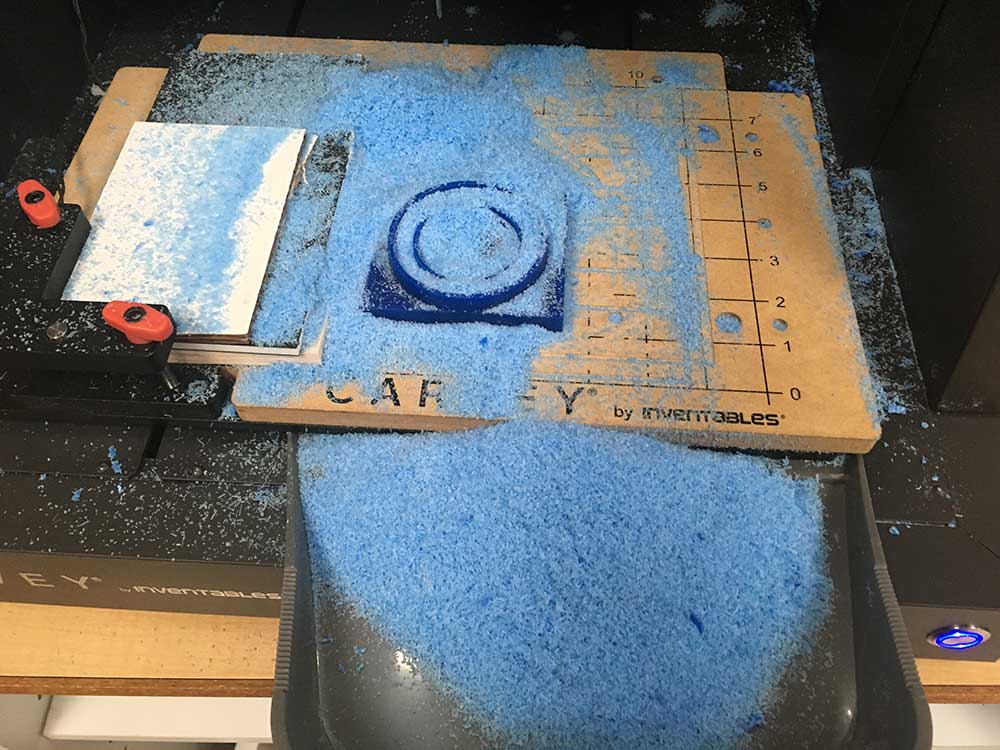
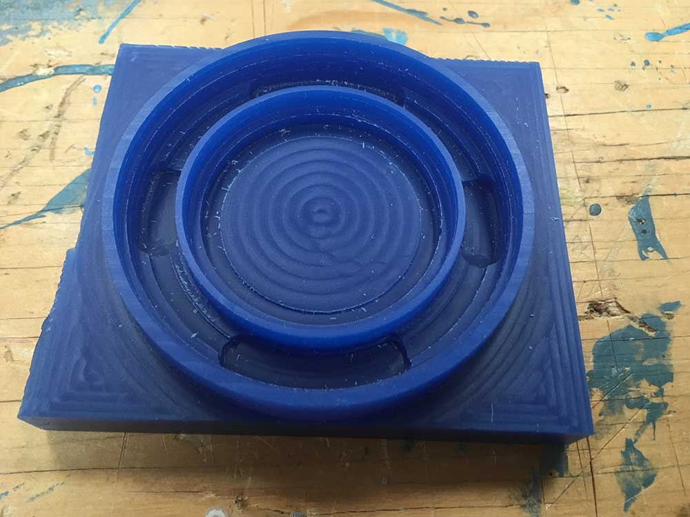
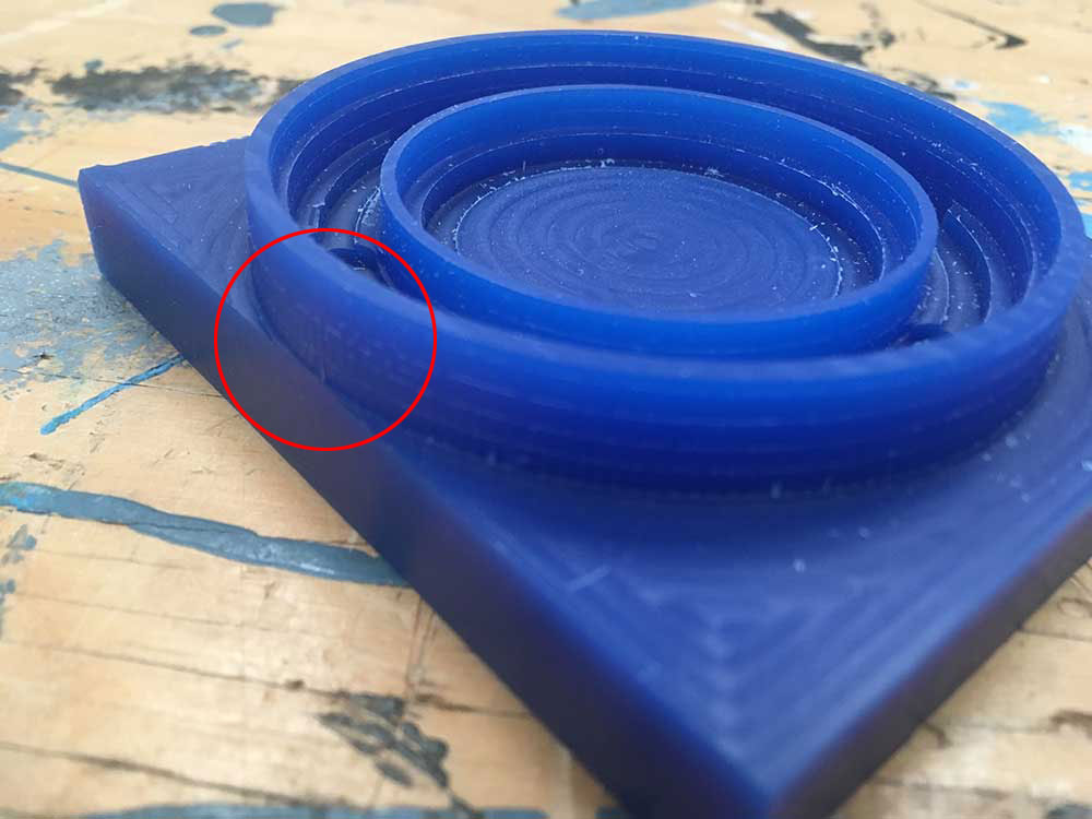
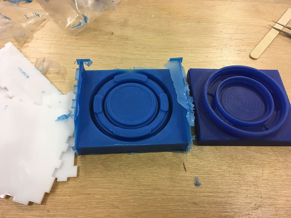
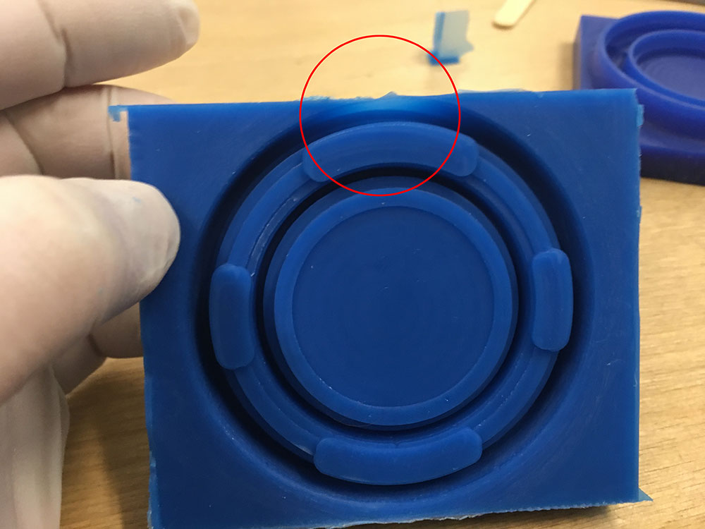
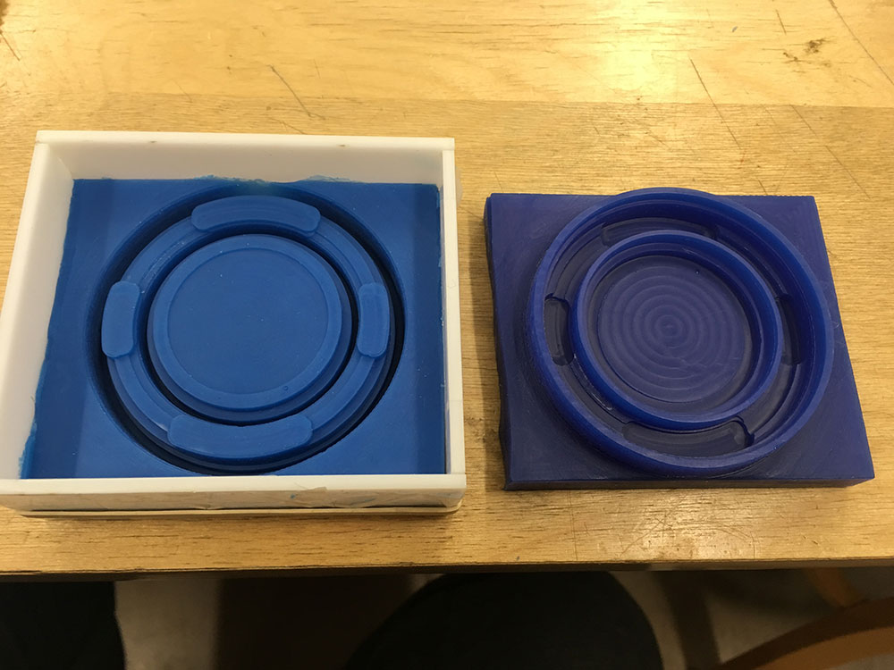
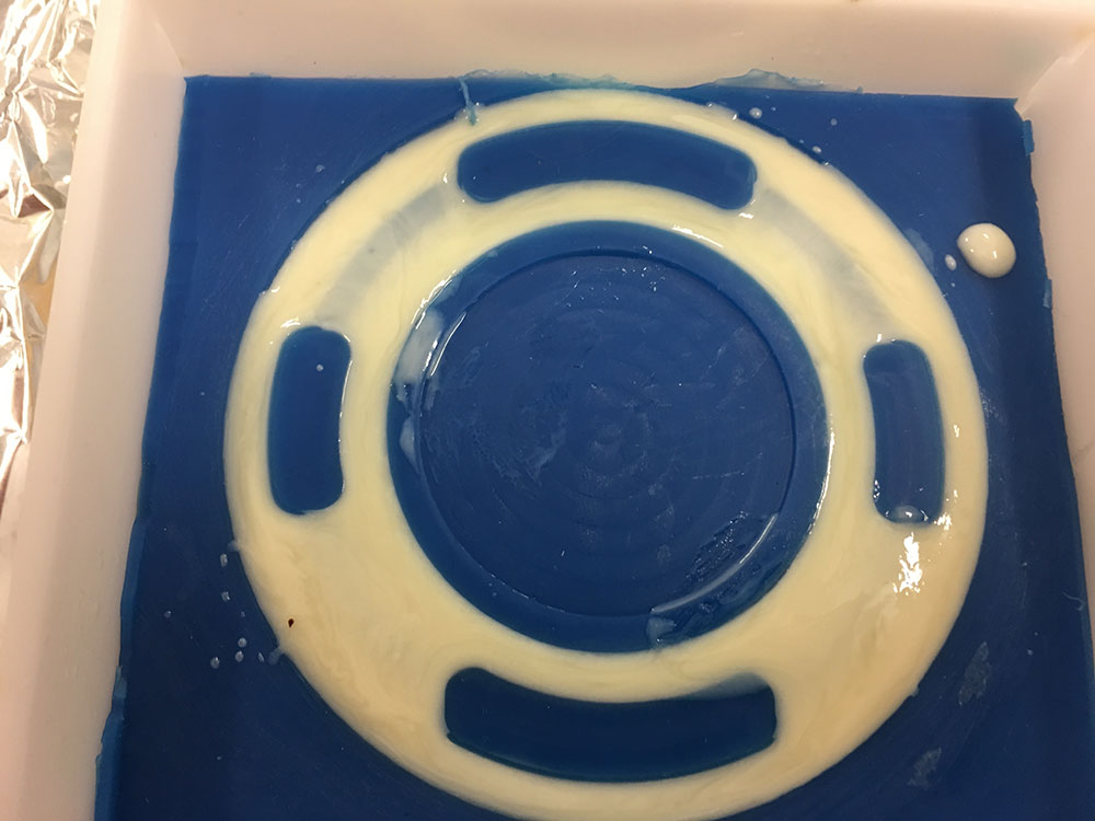
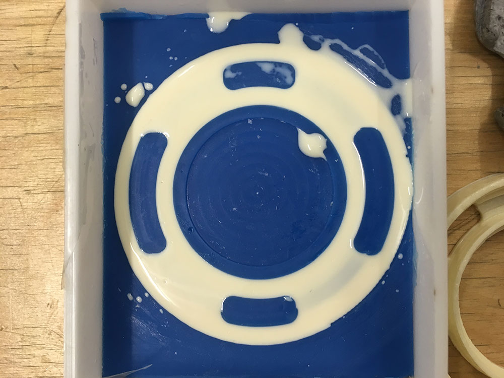
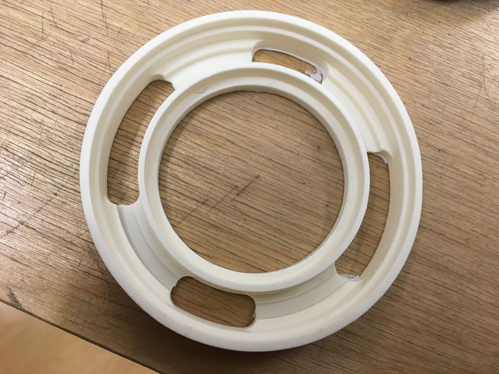
I then performed another facing operation after fixing the geometries so it wouldn't cut through the wall of the model as it did in my first try and I attempted to carve it again. The carving process was successful although it took a long time. The problem I was now facing was that my model takes up almost the entire width of the material leaving very little room. This resulted in a very thin perimeter wall of my model. The tooling was perhaps a bit agressive as well. Cutting through the pockets was a bit harsh and I had to pause the job a couple times to clear debris.
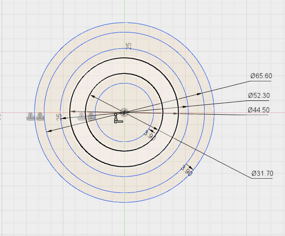
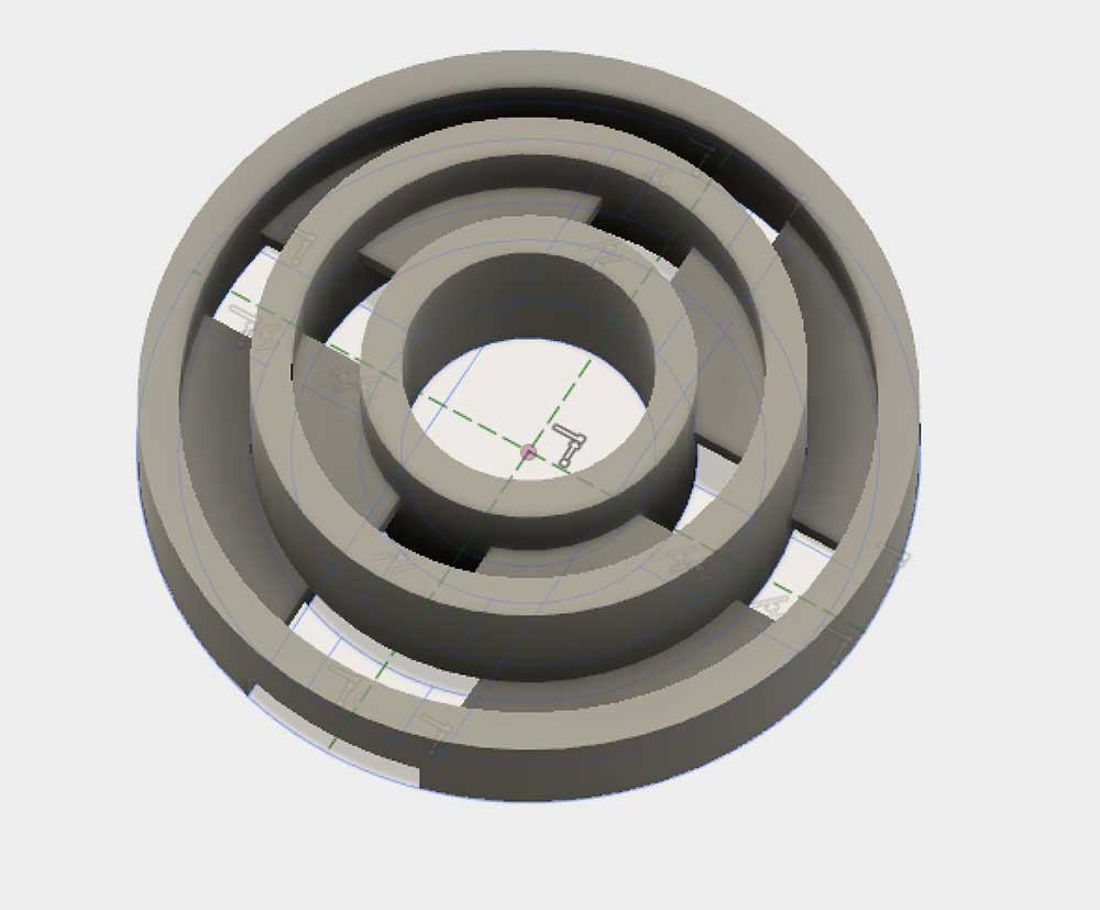
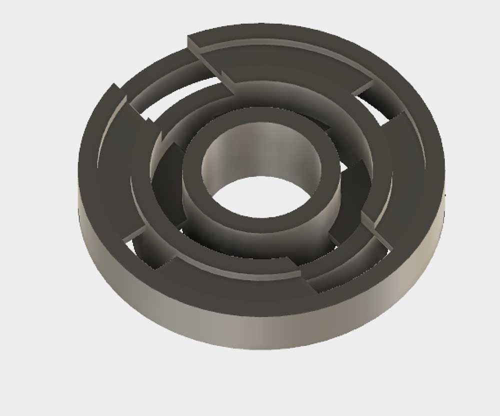
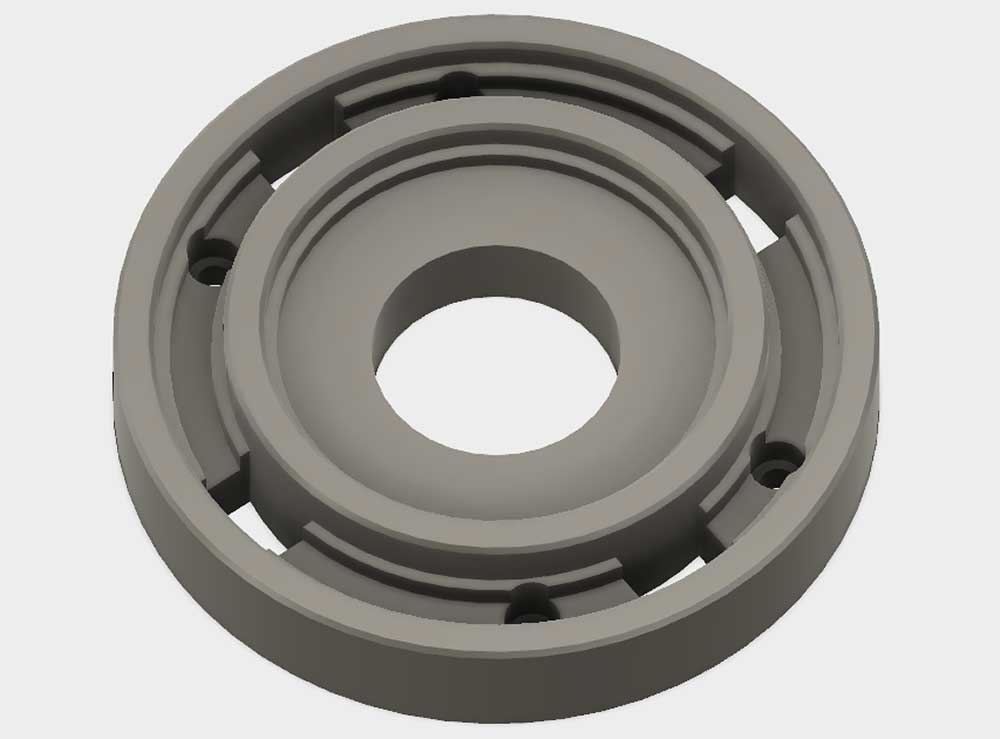
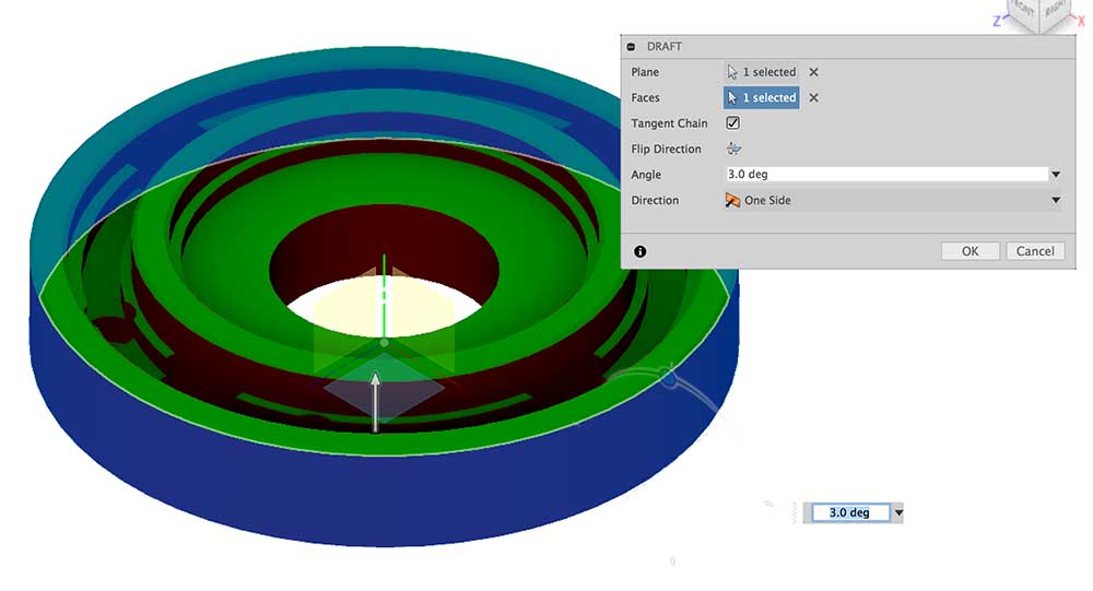
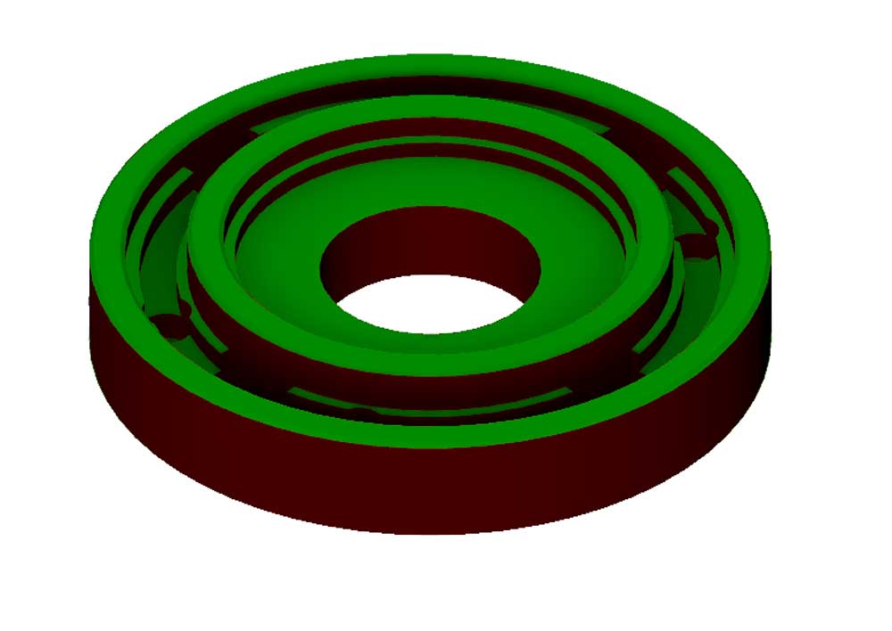
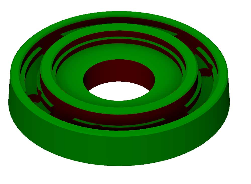
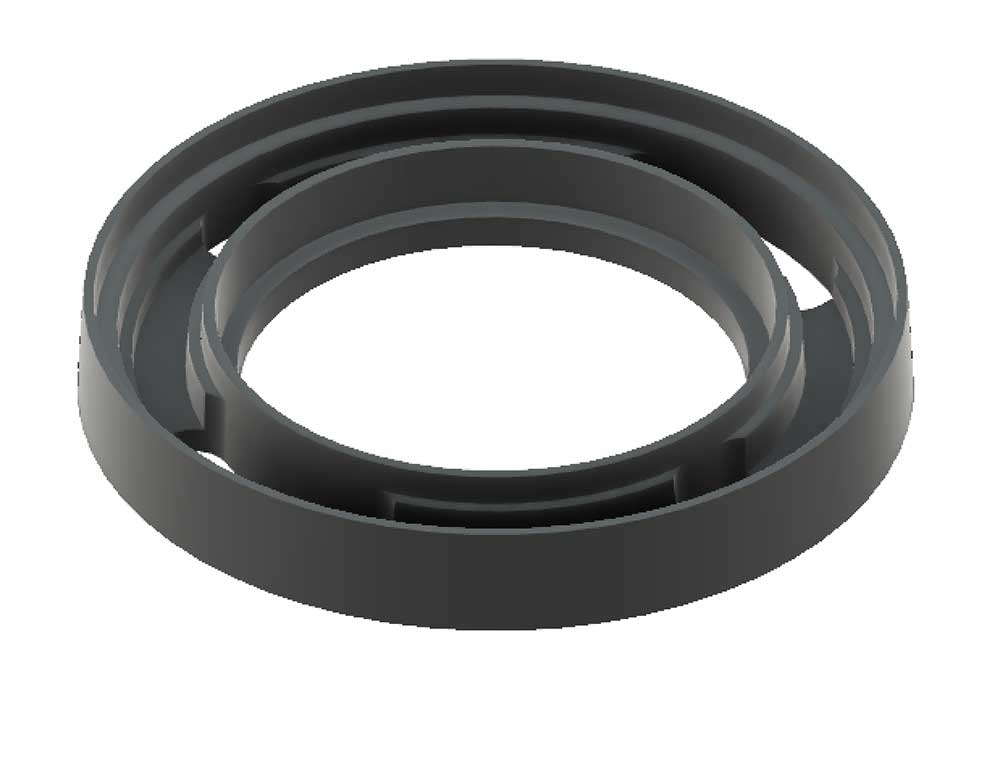
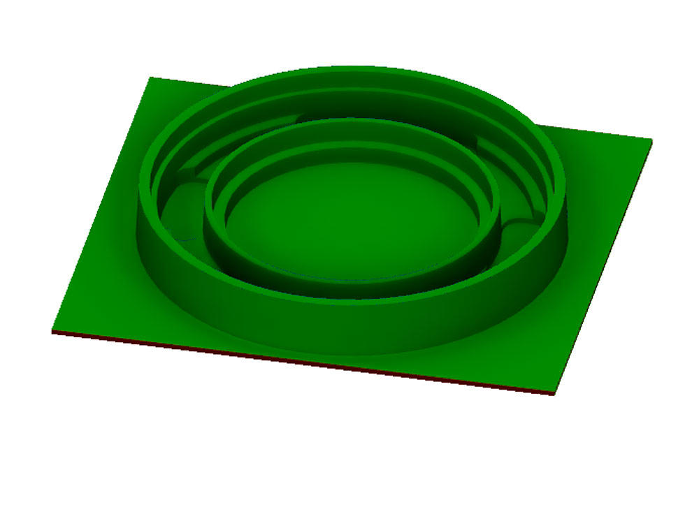
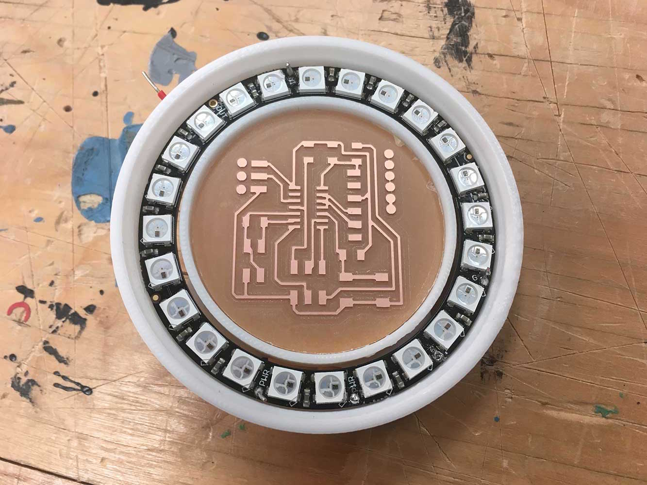
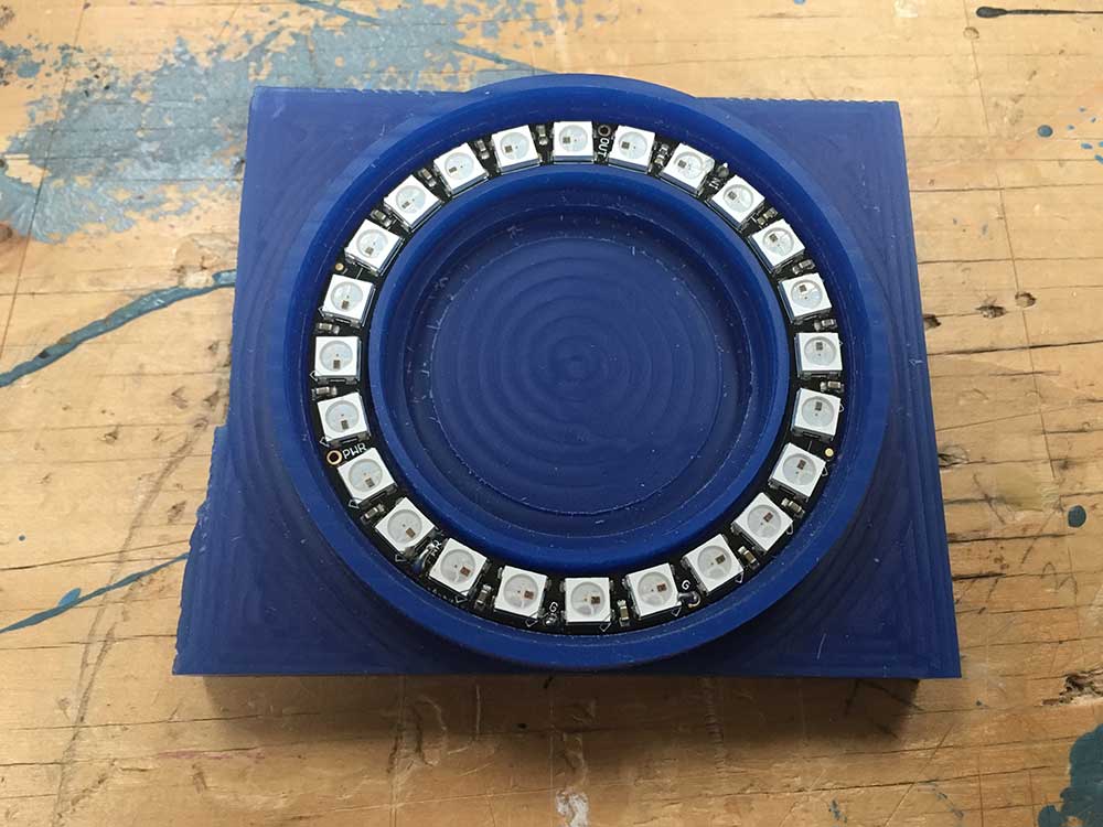
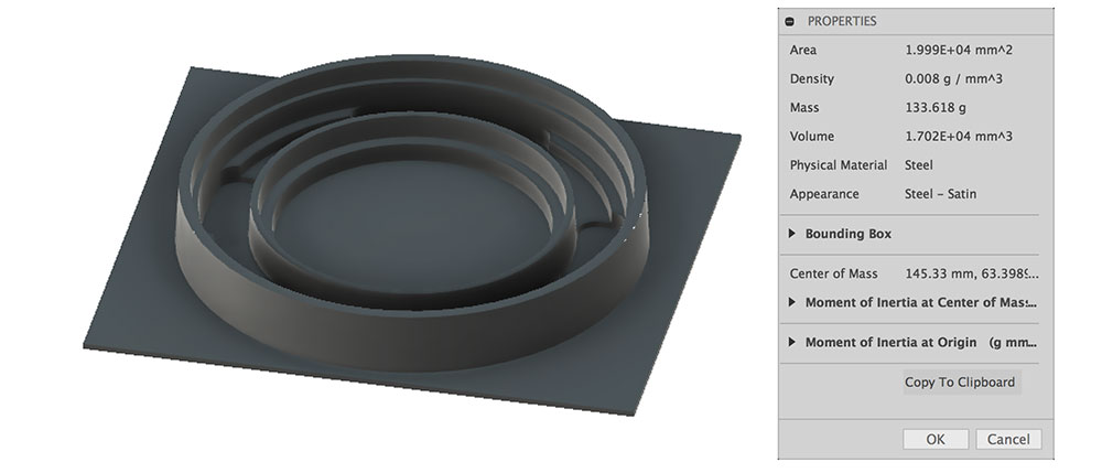
I decided I would do this again. I made some adjustments to my model by changing the wall thickness so that I would have a little more room to play with. Of course, I was limited by the fact that I was bound to the dimensions of the 24 LED NeoPixel ring I was using.





 x
x
