WEEK 5
ELECTRONICS PRODUCTION


ASSIGNMENT DETAILS
Group assignment: characterize the specifications of your PCB production process. Individual assignment: make an in-circuit programmer by milling the PCB, then optionally trying other processes


NOTE: For this process, I have a couple Milling machines I have access to. One is at EchoFab and the other is in the LCC Fab Lab. Both require different processes but together bring experiences from two different sides of the spectrum.


Echo Fab Mill

échoFab has a DIY mill that consist of a Hitachi Router in a frame made out of HDPE. At first we did not expect much from this machine but our instructor demonstrate how to get precision out of a tool that looked rather "un-precise". And it did!


Generating the gcode file.

We used Fab Modules to process the .PNG into G-codes(.nc)
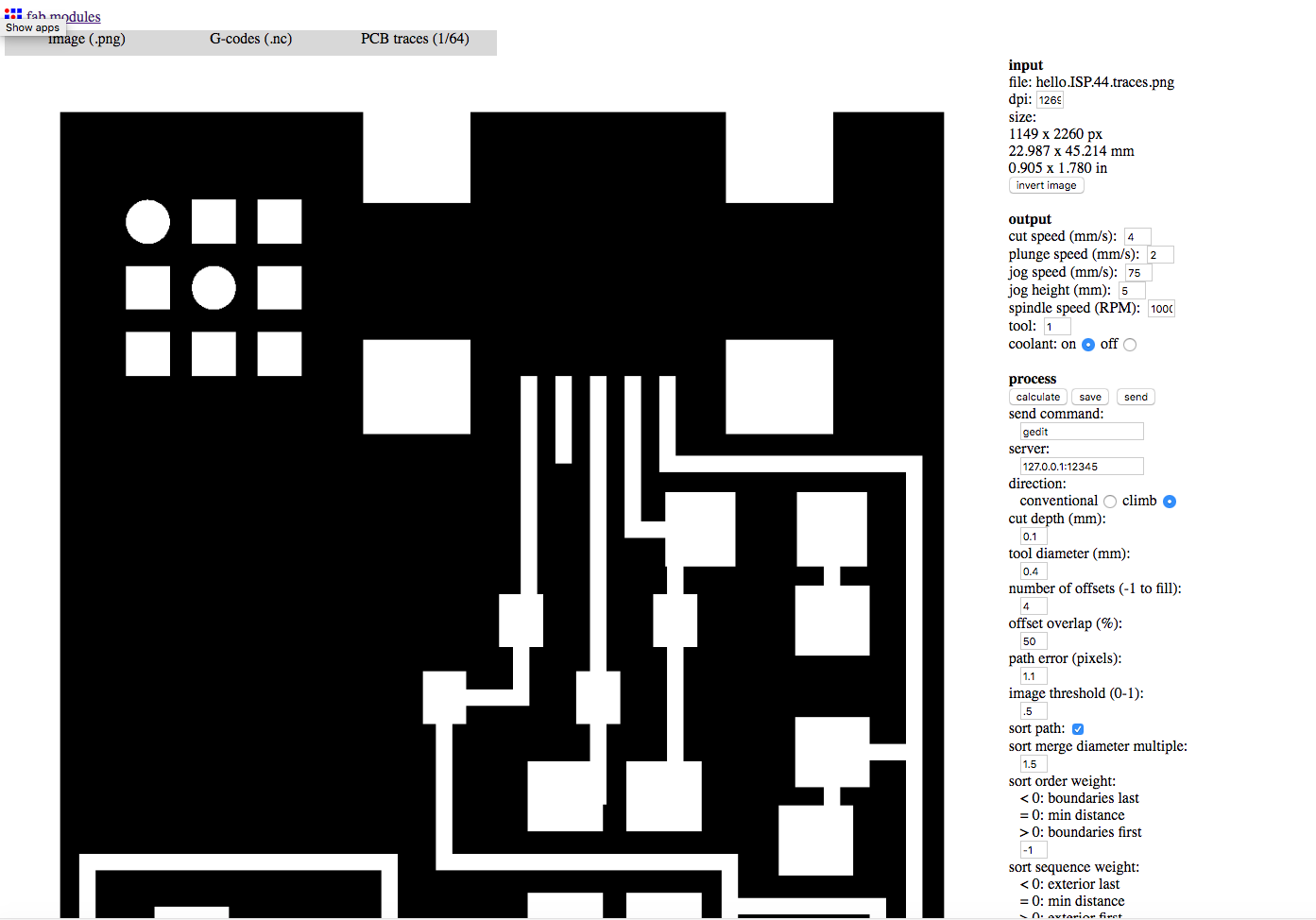

---> Input Format = image.png - select hello.ISP.44.traces.png
---> Input Format = G-codes (.nc)
---> Process = PCB Traces (1/64)

Here are the default settings for the échoFab mill. Because it is a router in a milling machine, the RPM setting will be ignored as this is set manually on the router which was set to "6".
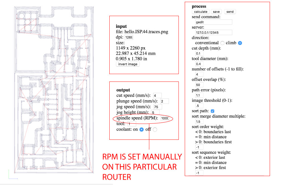


Milling with the échoFab Mill

Before milling, we need to set up the machine. It might look funny to see it on the floor but the results were better this way. Less vibration. First we need to add the 1/64" bit to the router. We do this with the machine "off"


Next, we need to place our PCB FR1 board on the flat surface using double-sided carpet tape and then we need to turn on the machine (not the router) and set the origin or "home" which is "0" on the x,y, and z, axes.


---> STEP 1: Connecting to the Machine

Connect to the machine by selecting the port and GRBL as your interpreter.
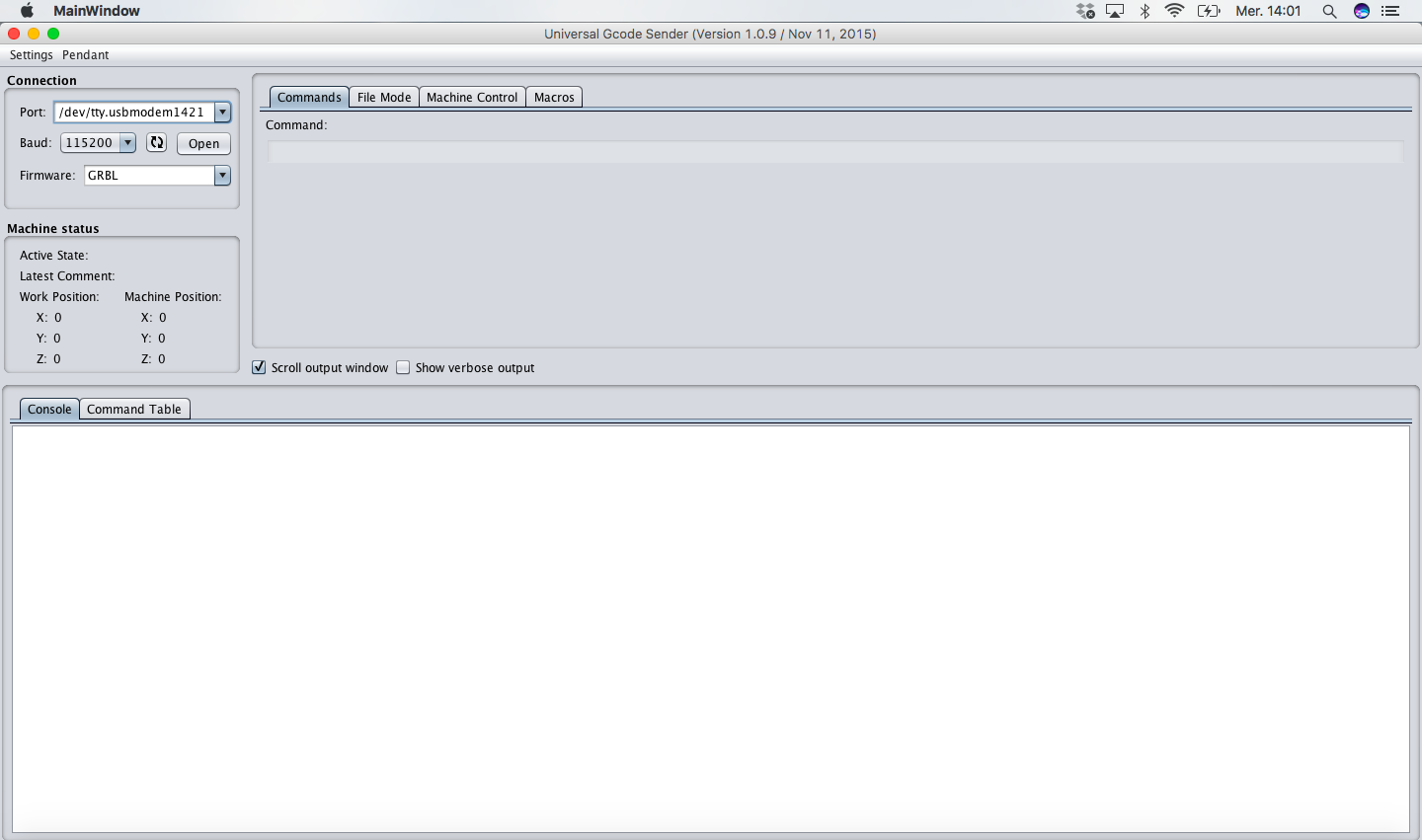


---> STEP 2: Setting the Origin

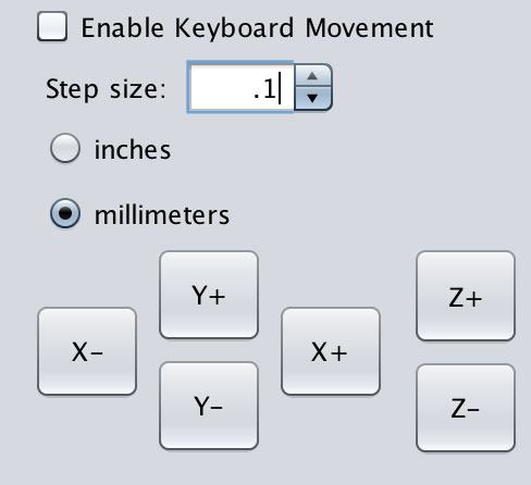
Navigate to the Machine Control tab and use the X,Y,Z, commands to move the router.
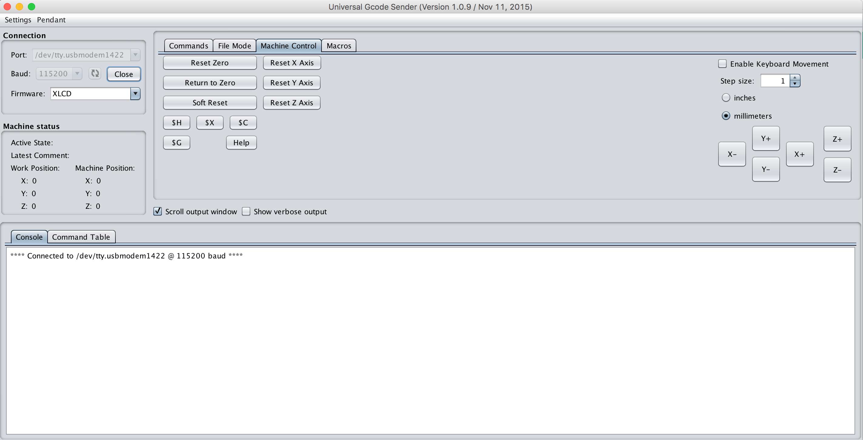
NOTE: Select 1 inch increments to move the router in large steps but as you get close to the origin or place you want your job to start, move in 1 mm increments and then 0.1 mm as you lower your Z axis. The bit should be close enough to the PCB board that a paper rubs when you slide it underneath.
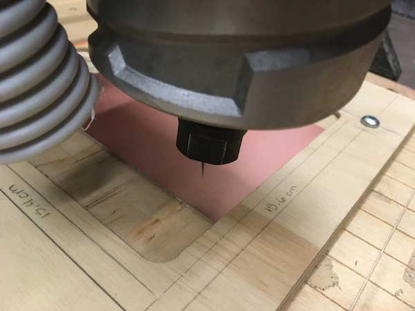
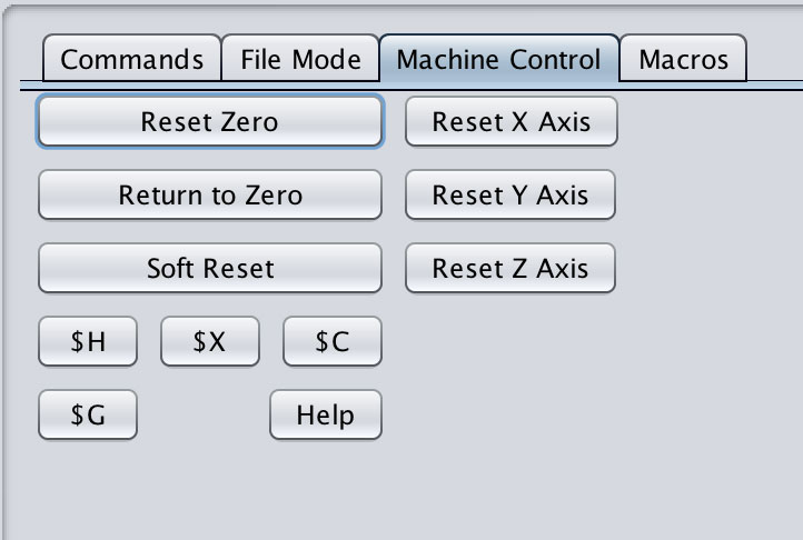
Select "Reset Zero" to set the new origin. Once this is done, it is good to move the router to another location and then select "Return to Zero" just to double check that it works.


STEP 3: Loading G-CODE

Navigate to the File Mode tab. Browse and find the hello.ISP.44.traces.nc file that was generated from Fab Modules and load it. You can press the "Visualize" tab to make sure the file looks as it should.
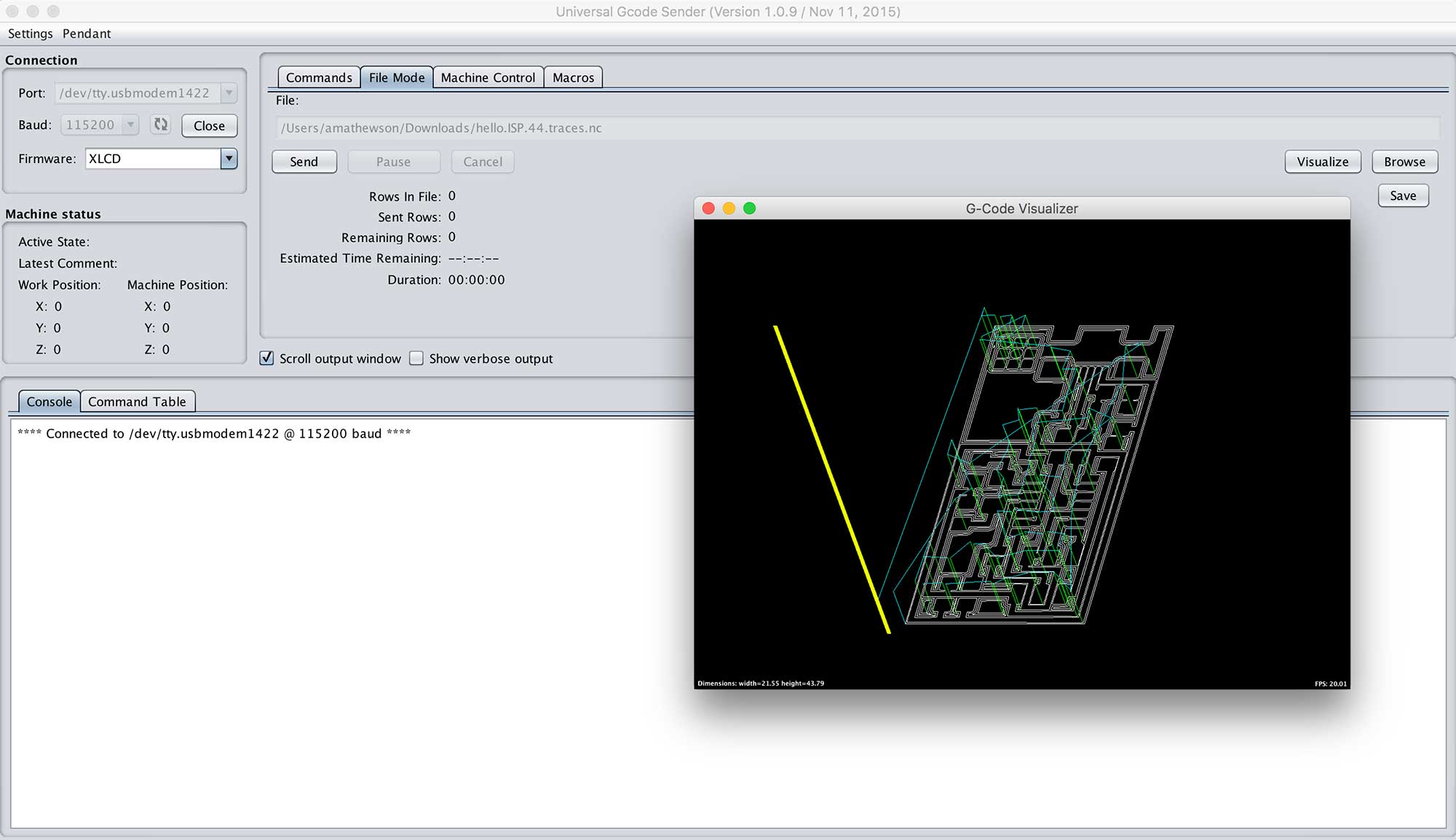
When complete, press "Send" and it will start to mill.
CARVEY

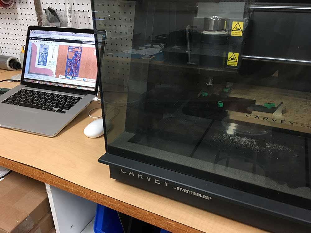
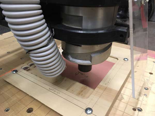
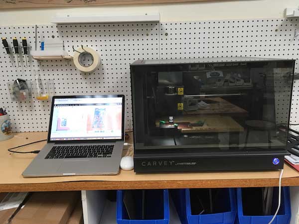
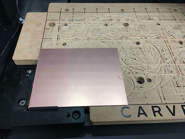
The day our group was milling at échoFab I had to go early so I decided to mill my ISP board using the Inventables Carvey at the LCC Fab Lab. This machine is as "kid friendly" as you can get. Which makes it great for schools but it is still a capable machine. This is my first time trying something as precise and PCB milling. While Inventables sells this feature, the information and presets for this kind of process I find are lacking.


STEP 1: Setup Material

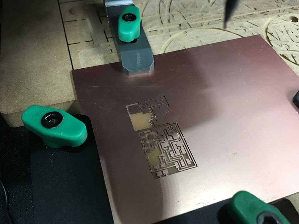
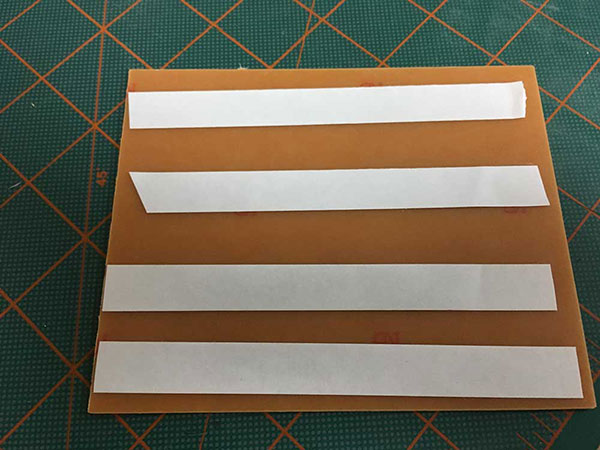
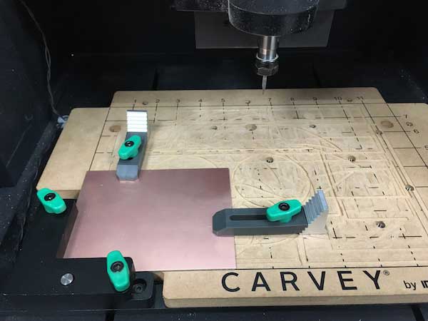
Setting up the machine is extremely simple. I added double sided tape to the bottom of my PCB board and I positioned it in the corner where the "smart clamp" is located. This machine uses the smart clamp to home. While it makes setup almost effortless, there are times when the clamp gets in the way. It takes up a lot of real estate on smaller objects. For more information on the Smart Clamp visit HERE.


I wasn't sure if the tape was enough alone so I added clamps. It turns out I later realized that teh double sided tape is all that is needed. The wasteboard had lots of cuts in it but the piece was still quite level.


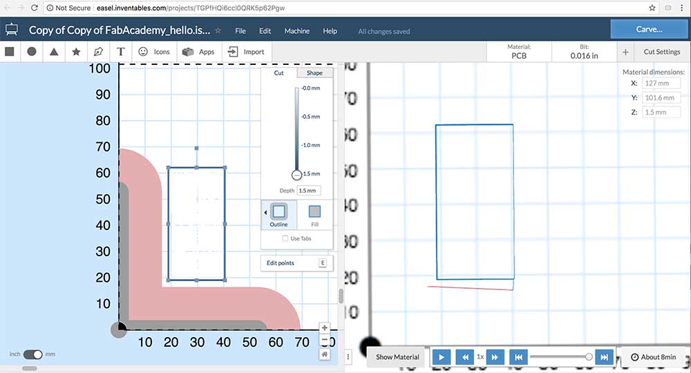
STEP 2: Setting up EASEL

Inventables, the maker of the Carvey Mill, make a tool called Easel. I don't like that it is run through their website but it has definitely made the process of milling relatively easy. It is only one of a few ways you can run this machine. You can also load gcode from Fusion 360 which I will try during in the Molding & Casting week. Apparently, you can use Universal Gcode Sender but this will void the warranty on the machine. Seeing as our Warranty is just about up, i will try this in the future. In the meantime, I just wanted to see how the machine would do with PCB Milling.


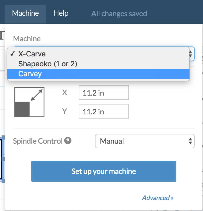
---> Select your carving machine


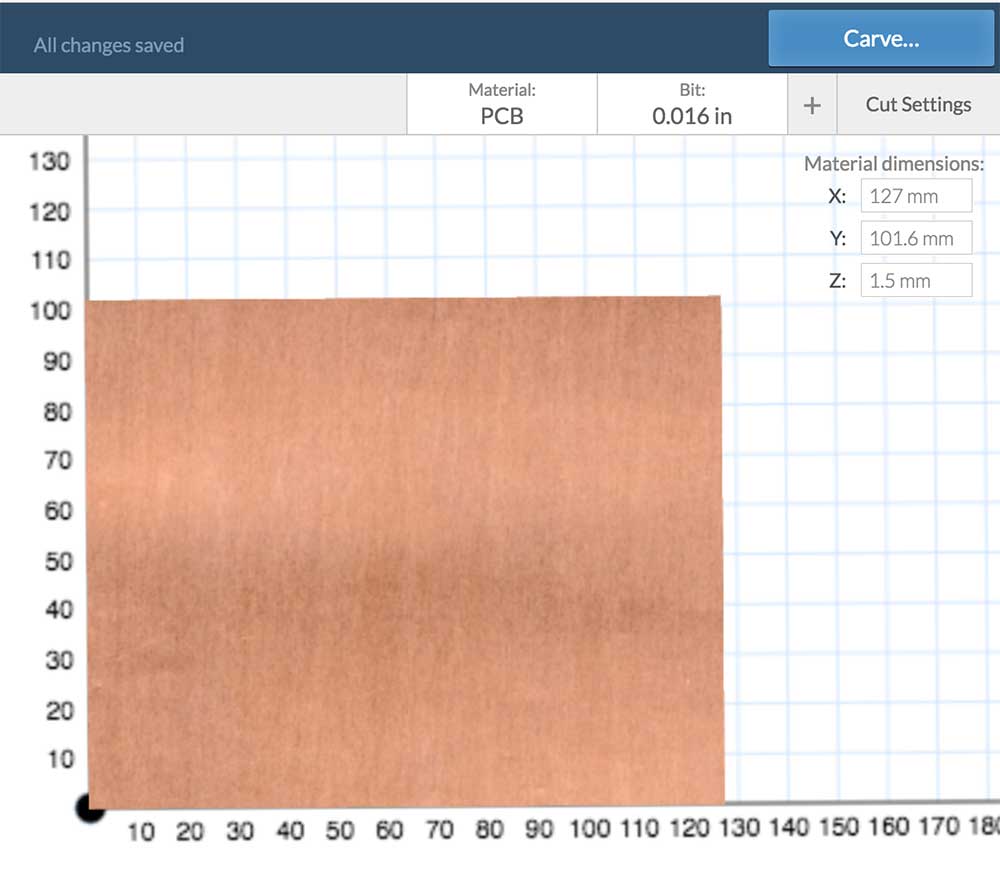
---> Enter your material dimensions.

NOTE: We are using 5x4" panels of FR1 PCB board. By selecting the material type you are giving initial settings or presets for that material.


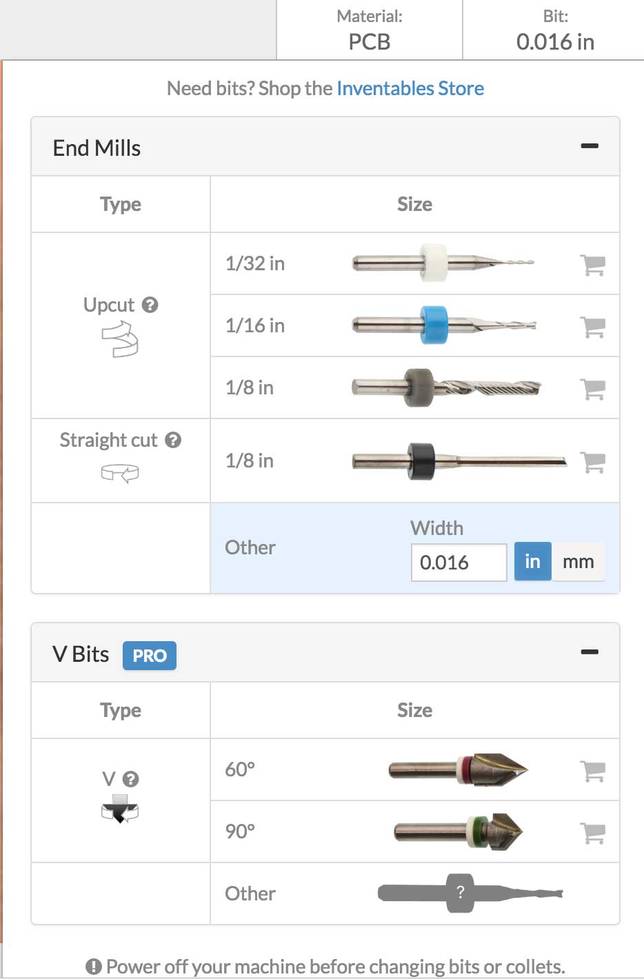
---> Select your bit.

This surprised me. There are no presets for the PCB milling bits even though they sell them. I contacted Inventables and they confirmed this. Why market a process if you do not support it like the others. I was wondering if maybe there are some limitations to milling PCB board. You have to add in your bit manually. I was using a 1/64" or 0.016" flat end bit.


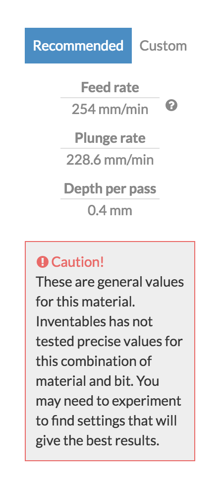
---> Set your feed and speed.

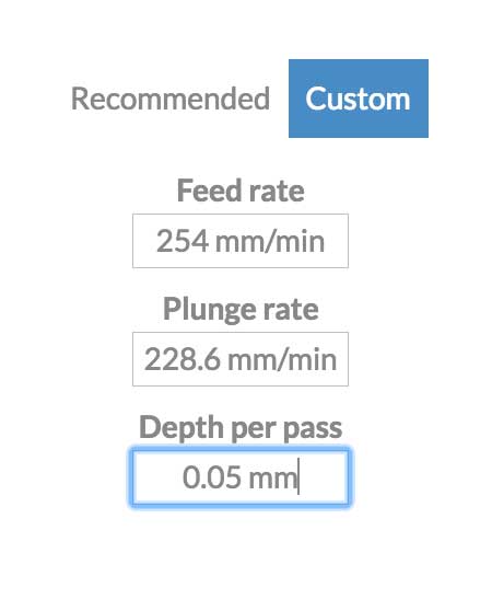
Another surprise. The recommended setting for Depth per pass seemed high for a material where you want to remove 0.05mm of copper.


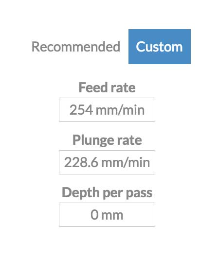
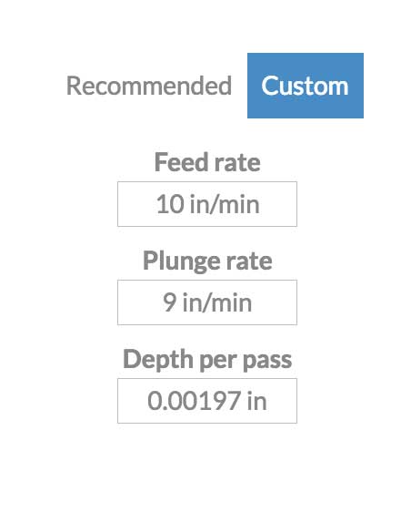
I chose to set custom values. Keeping the feed and speed the same but changing the depth to 0.05mm. For some reason the software would round up to 0. After some searching around, I found out there are some discrepencies in how the software interprets metric vs imperial. By changing the Easel to display in Imperial, you will see that the value is set.


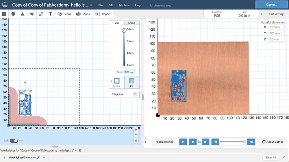
---> Import your file.


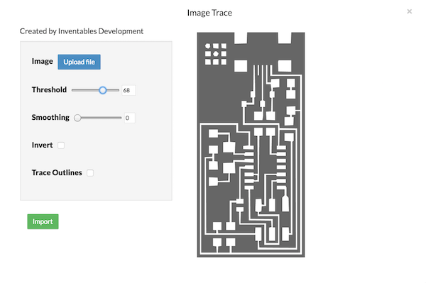
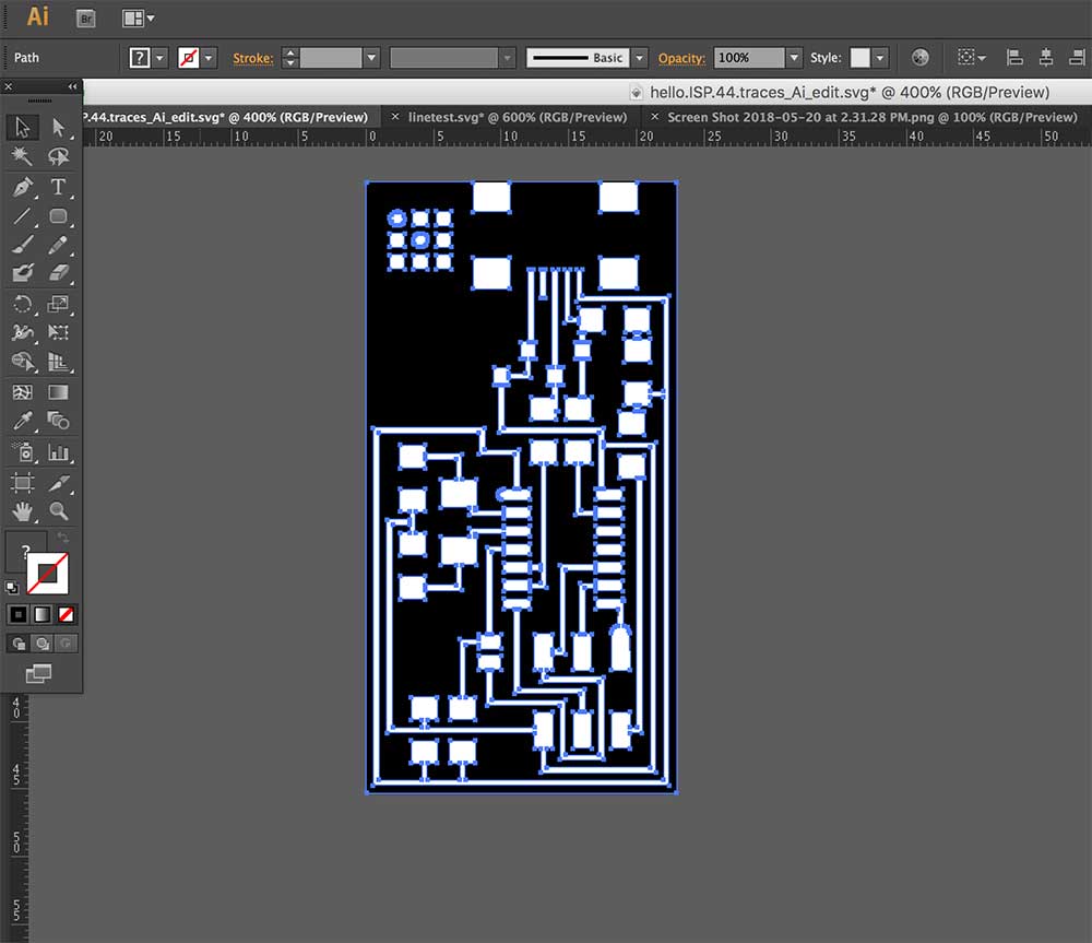
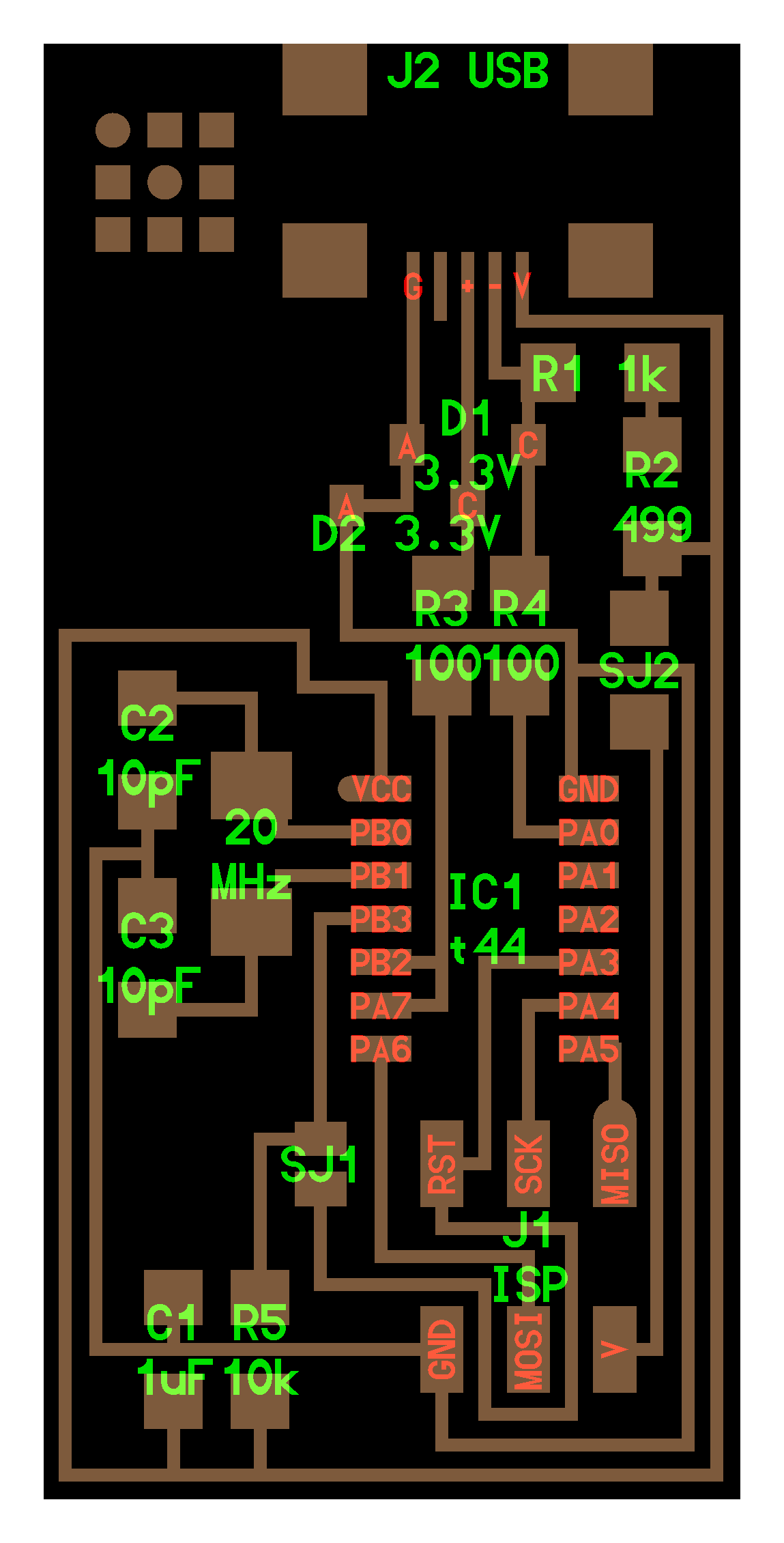
Once Easel was set, I needed to import the image for the hello.ISP board. Easel accepts .SVG or GCODE or it can also do an image trace of another image file. I tried this with easel but I did not like the results. Even with smoothing off it was hard to get straight angles. I chose to trace the hello.ISP.44.traces.png file and convert it to an SVG using Adobe Illustrator.


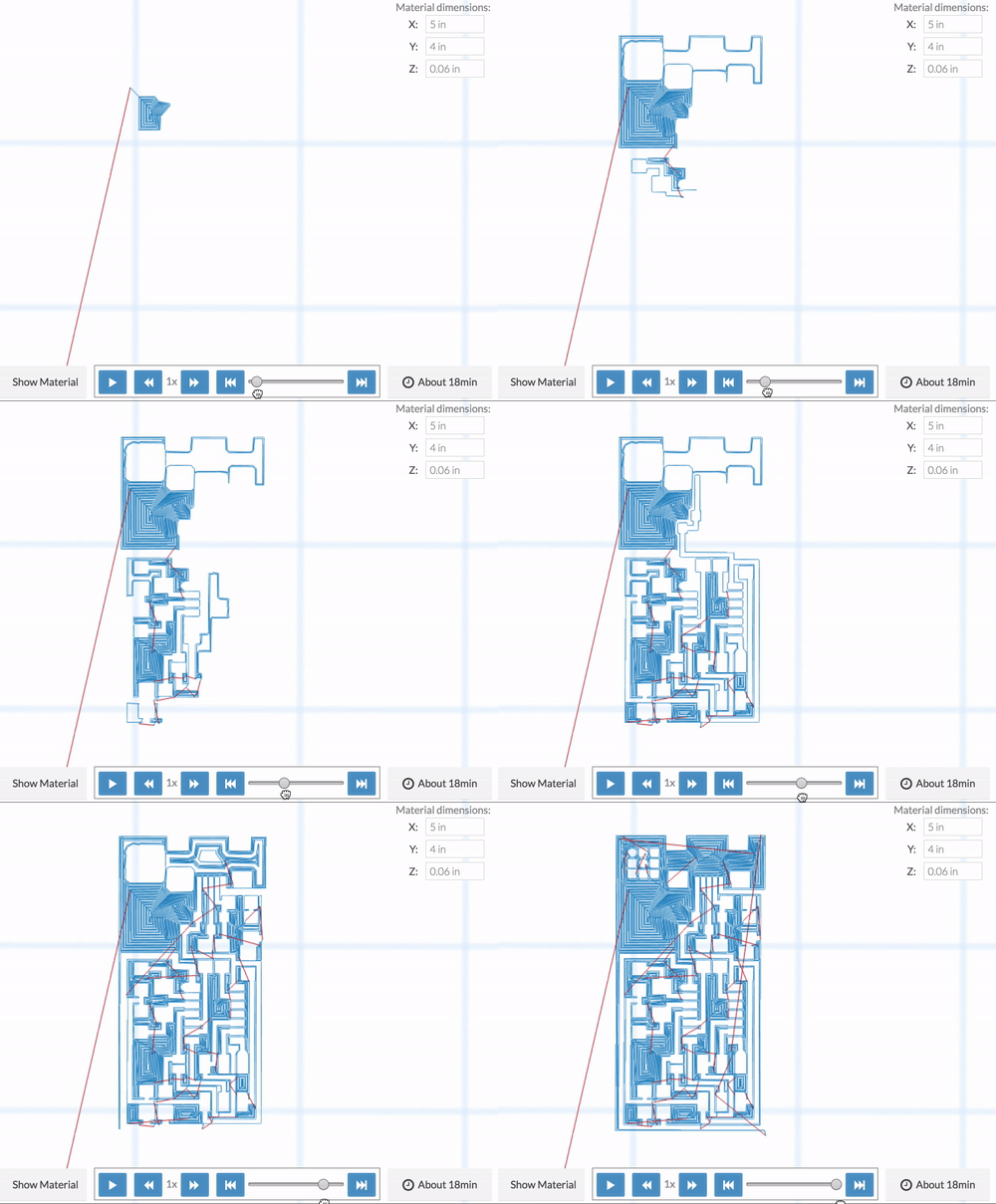
With the SVG file successfully loaded I positioned it and set the cut depth. You can select background fill or outline. I chose outline which will result in cutting away all the copper outside of the traces. I set the cut depth to 0.05mm then I pressed simulate and checked that all the traces looked complete or not joined. If you choose the wrong bit or depth you will see anomalies in your preview pane. Easel has been pretty accurate at detecting visualizing these.


---> Carve.

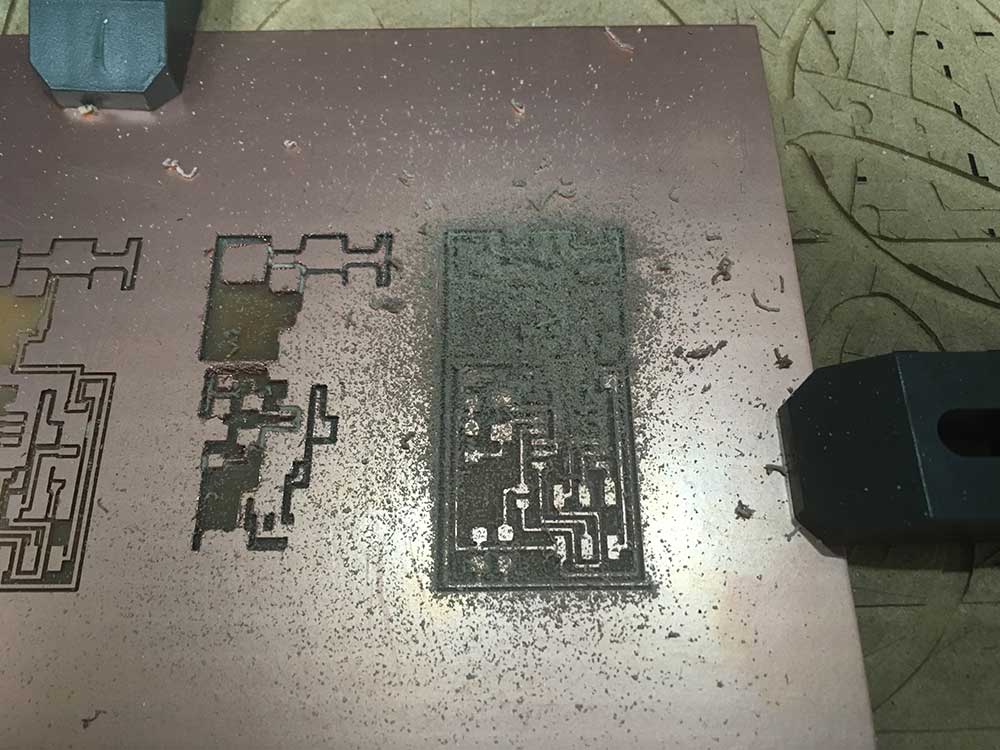
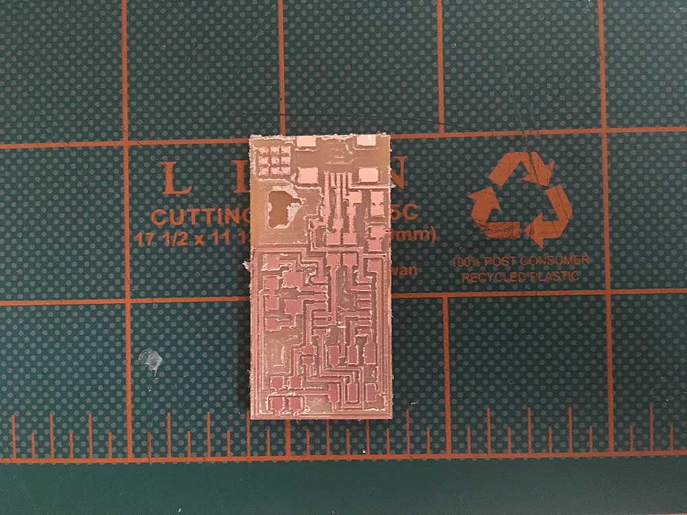
I started carving. Things were looking very good. I paused to vacuum and have a look. The depth of the cut seemed to be deeper than 0.05mm but the milling was surprisingly clean.


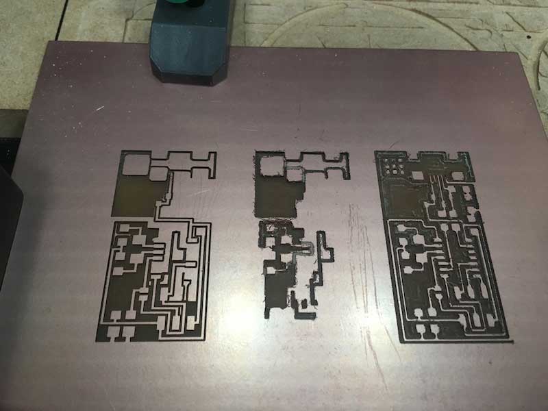
What I didn't realize is that I grazed the bit with the vacuum and broke it. This was the only bit I had so I continued with a broken bit.


You can see the different from left to right.


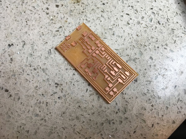
I set up a new board, completed the milling and then cut out the outline using a 1/32" bit. This time you set the depth to 1.5mm to cut all the way through and you make sure you are cutting an outline.


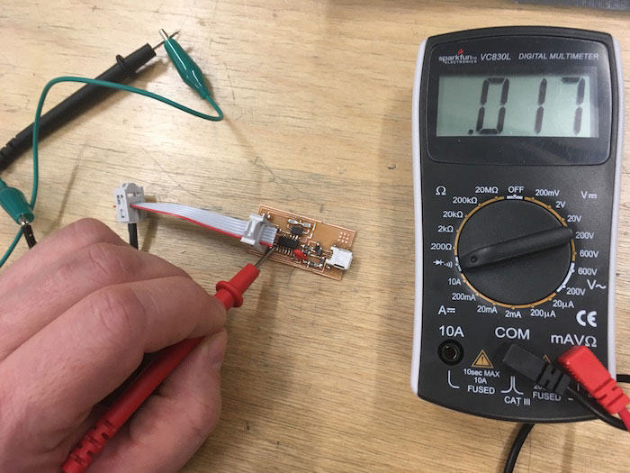
This is what milling with a broken bit looks like. I did not have another bit and I had to move on to electronics. I checked with a multimeter. All traces connect so I continued with this board. Applying a little sand paper makes a big difference.


ELECTRONICS


---> Collecting the parts.

Before starting, I read more info on the hello.ISP.44 board by reading Ali Shtarbanov's page which nicely describes what is going on with the electronics on the board. Using the "board" and "component" examples on the Fab Academy Lecture page for this week, I collected all the parts I needed.


PARTS LIST
---> atTiny44 microcontroller
---> 5 resistors (1 x 1k, 1 x 10k, 1 x 499ohm, 2 x 100ohm)
---> 2 jumpers (0 ohm)
---> 3 capacitors (1uf, 2 x 10pf)
---> 2 diodes (3.3v zener)
---> 1 20mhz crystal
---> 1 Micro USB connector
---> 1 6 pin header

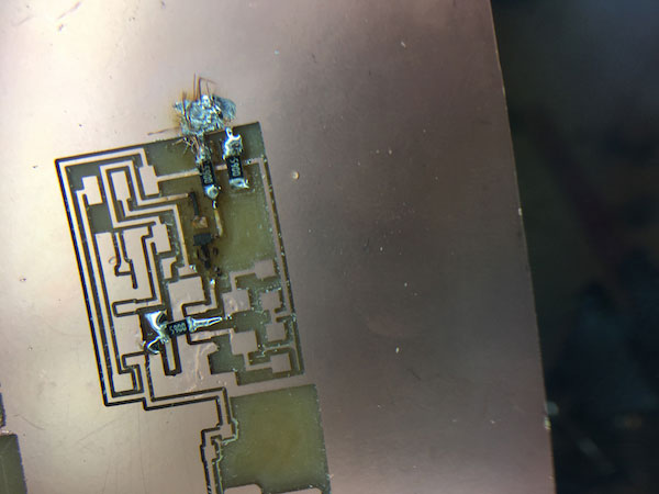
I was really concerned this would be a real challenge. So I chose to do some tests soldering on the wasted PCB boards from the milling process. It took a few tries but I eventually felt comfortable enough to begin this process.


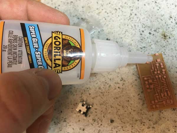
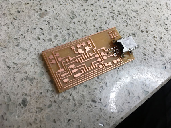
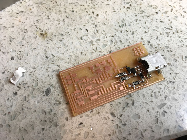
I started with one of the harder parts. The micro USB connector. I put a little drop of super glue between the traces to help keep the piece in place.


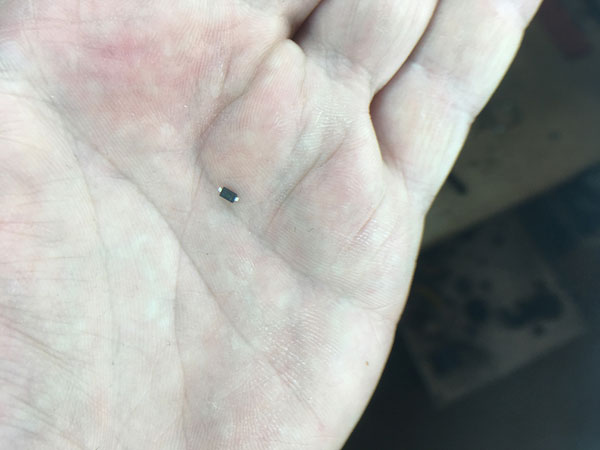
I still can't get over the size of these pieces.


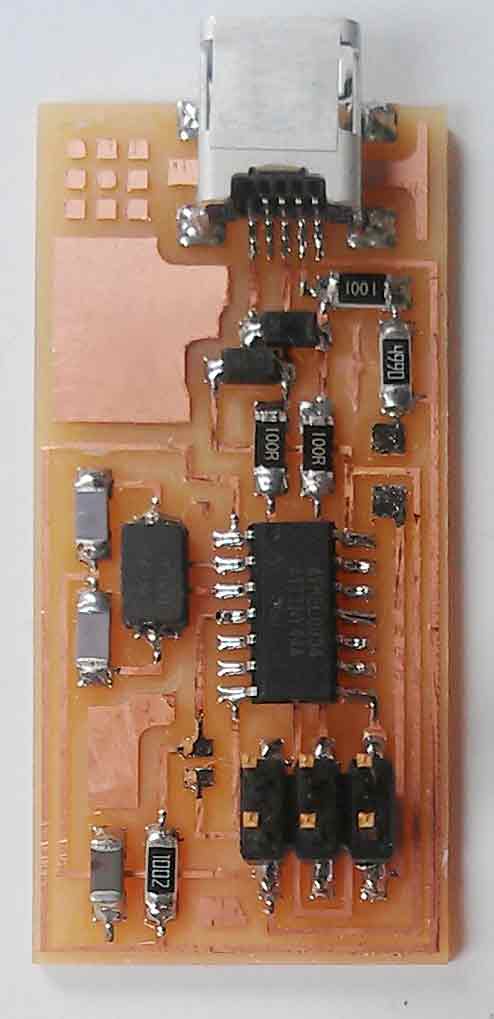
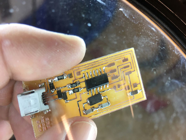
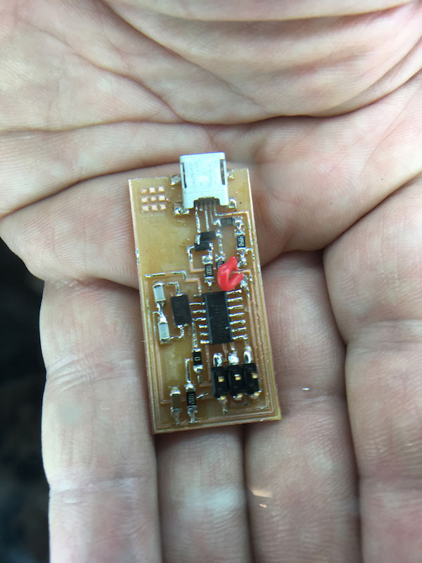
Moving down from the USB connector I started to see the board take shape and I was getting quite comfortable. It is certainly not beautiful or anything like the examples on the Fab Academy site but it was working.


Having removed all the copper between the traces really made getting soldering the ATtiny44 and other small parts as the solder does not like sticking to the bare FR1 board.


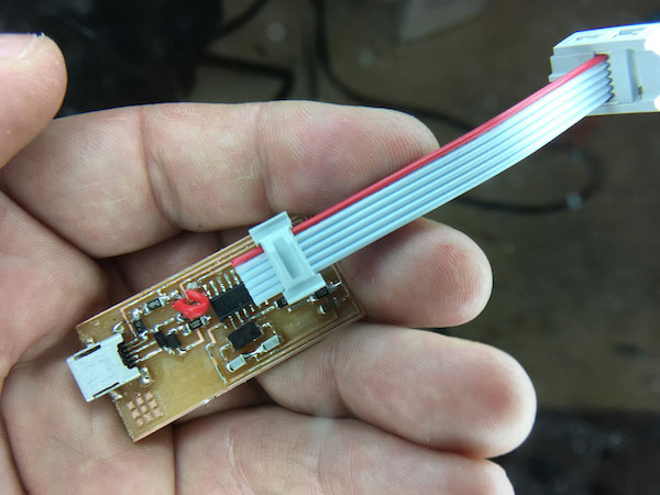
The last part I soldered on was a red wire in place of where the 0 ohm jumper would be placed to send power from the USB cable. I followed the example of our intsructors board. Keeping this jumper active makes it possible to power your target board without the need of a second USB cable.


Not using a small 0 ohm resistor makes it easier to remove or add back on. I also made my ribbon cable but realized I made it too small and I should have wrapped the end back into the clip instead of leaving out straight. After everything was connected I checked all my traces, cabling, and resistors.

I was especially proud of myself for making this. It was fun and I can see the appeal of working with surface mount electronics versus traditional breadboard and through hole circuitry. I only hope it survives the upcoming smoke test!


PROGRAMMING THE ISP

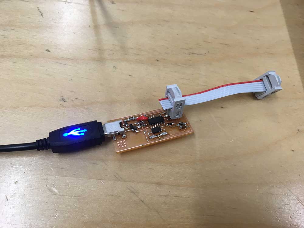
It seemed like I got through the electronics relatively easily. I was not expecting the same ease with the programming. First things firts... smoke test! I plugged the ISP in directly and no smoke!


Next I plugged it into our instructor's FabISP - making sure to get the orientation of the cable right. It would suck to burn your board at this stage.


---> Installing AVRdude / GCC

Following the instructions on the Fab Academy tutorial page HERE, I installed Crosspack AVR and followed these steps:


---> Download Fab ISP Firmware.

After downloading the ISP firmware onto my desktop. I navigated to the "Makefile" in the root of the ISP folder fabISP_mac.0.8.2_firmware and opened it using Text Edit


---> Selecting your programmer.

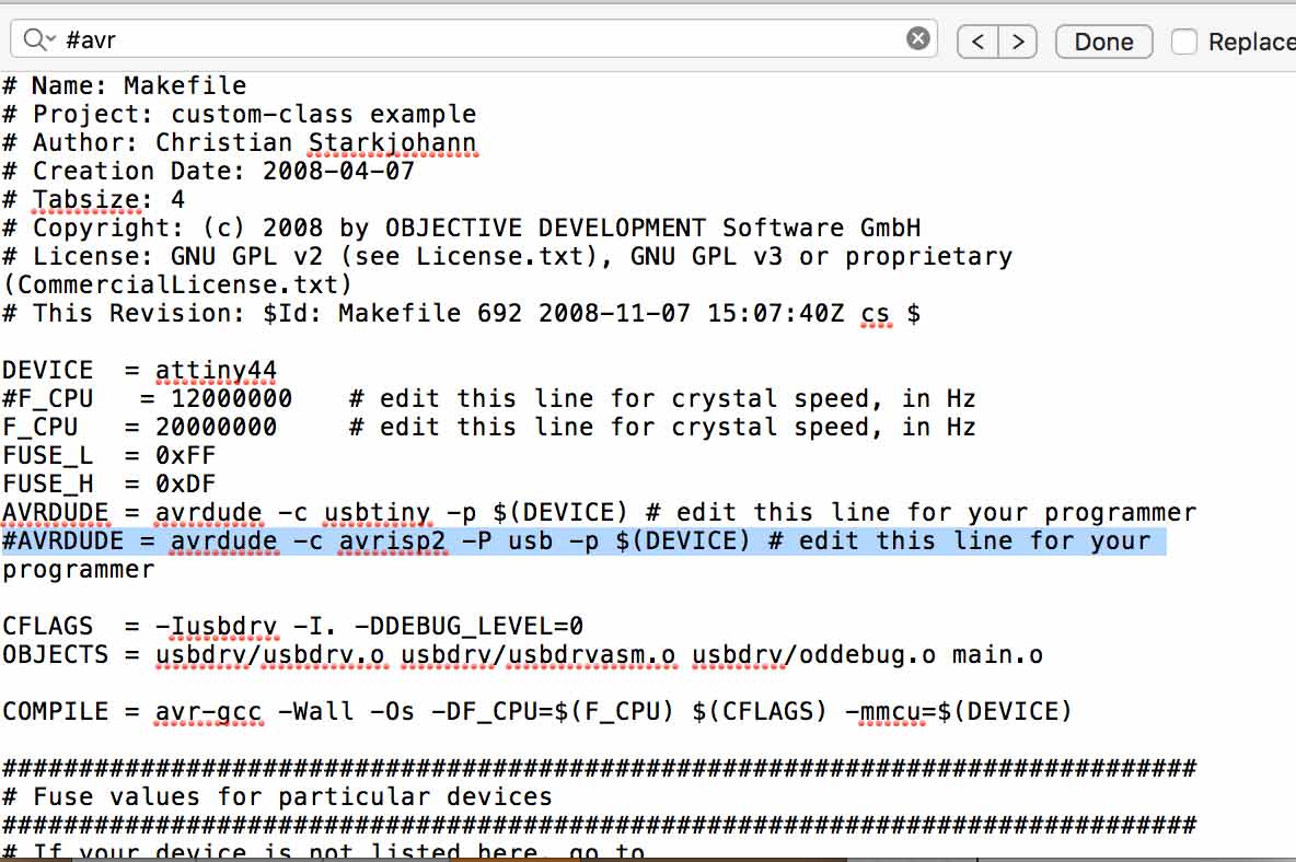
In the Makefile, there are two lines which tell you what kind of programmer you are using. In our case, I was using my instructors FabISP which is based off of the USBTiny programmer. As directed, I made sure that I moved the the hashmark (which tells the program to ignore the line) from the line containing USBTiny to the line below with AVRISP (which we are NOT using).


---> make clean

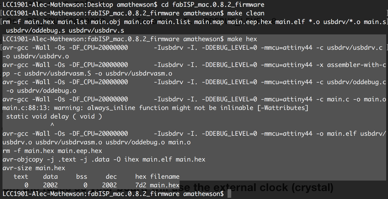
Next, I navigated to the same fabISP_mac.0.8.2_firmware folder using my Mac's terminal and typed make clean and received the following message...

A first success!


---> make hex

Next, following the instructions, I typed make hexand received the following message...

Another success!


---> make fuse

So far, I am feeling pretty lucky. Next step, I typed make fuseand received the following message...

Fail!


---> Using an Arduino as ISP

I tried several times and used an original USBtiny but kept getting an error. In reflection it was probably a simple mistake but I decided to try a new approach. Using Arduino as ISP.

After reading the following fab academy pages I followed instructions and set up my Arduino as an ISP.
http://archive.fabacademy.org/archives/2016/fablabaalto/students/294/articles/making-the-fab-isp/
http://archive.fabacademy.org/archives/2016/doc/arduinoisp.html


---> Using an Arduino as ISP


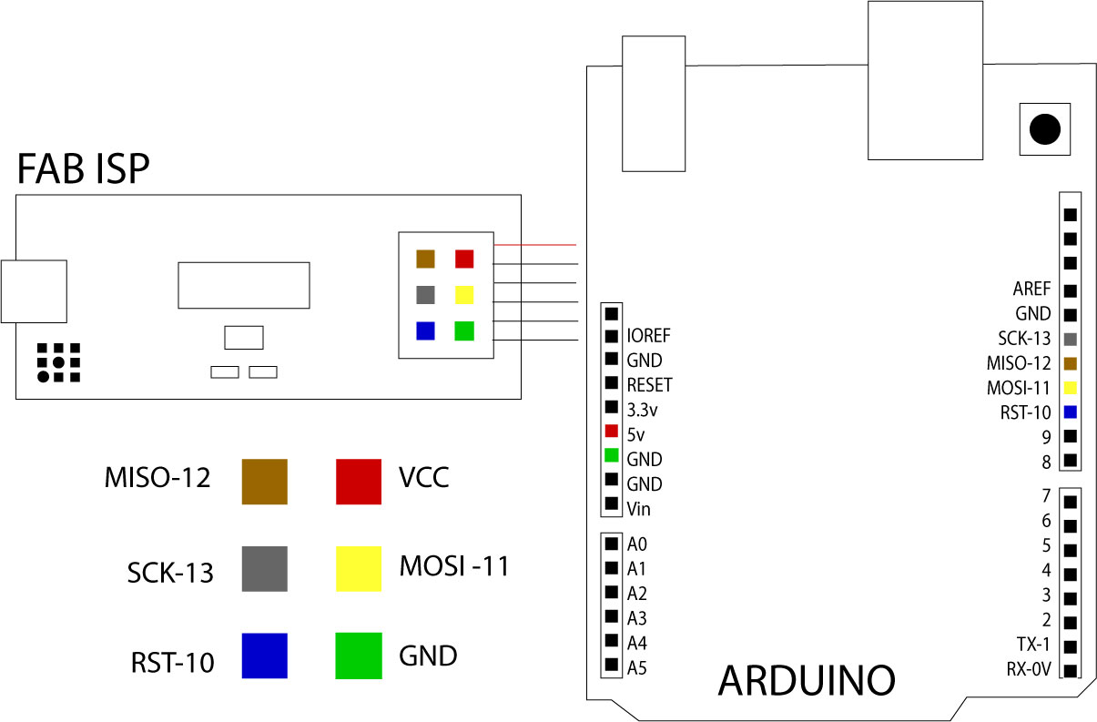
Make the following connections
---> RST = pin 10
---> MOSI = pin 11
---> MISO = pin 12
---> SCK = pin 13


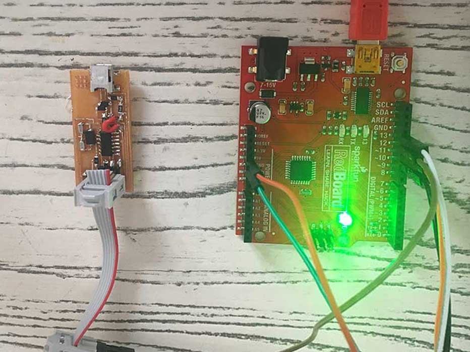
NOTE:Wire colors of the image below don't match the diagram above.


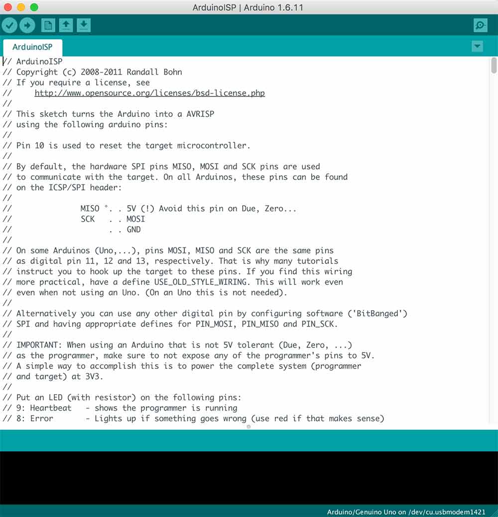
---> Upload Arduino ISP sketch

---> Adjust Makefile

To make this work you need to add the Arduino as a programmer in the Makefile. I hashed out the two previous programmer lines (AVRISP & USBTiny) and added the following:

NOTE: You need to include the USB port. In my case it was /dev/cu.usbserial-DN026GBP


Now that everything is set up I re-executed the above steps.
---> make clean
---> make hex


---> make fuse

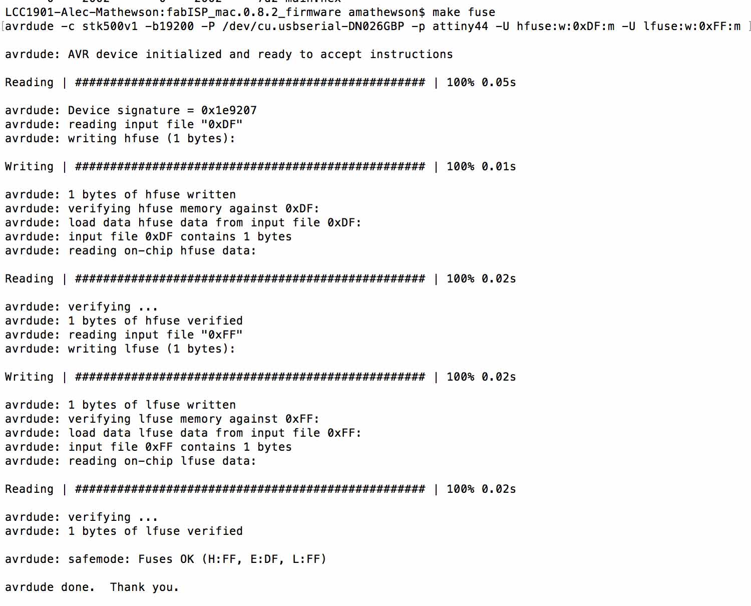
This time when I instructed make fuse I got the following response:

Big success!


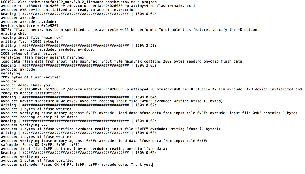
---> make program

hoora!


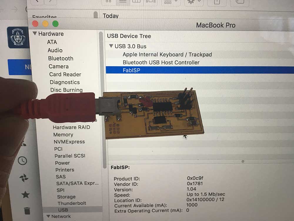
---> verify connection


ASSIGNMENT FILES


---> hello.ISP.44 svg:hello.ISP.44.traces.svg


Creative Commons License
This work is licensed under a Creative Commons Attribution-NonCommercial-ShareAlike 4.0 International License.