Design and build a wired &/or wireless network connecting at least two processors
This week I explored a lot. Lots of experimentation. Lots of learning. Lots of trial and error. Lots of troubleshooting. A lot of the learning during this week has helped me discover what will, and will not, be feasable to incorporate in my Final Project. In addition to the HelloWorld series of boards I have been spiral-developing, I will also explore a couple of module devices discussed by Neil. One is a WIFI (802.11) device and one is a Bluetooth device. I did not see any of these devices, or "modules" in the LCCC FabLab inventory, so I ordered some. In a continuation of my exploration of CBAmods this year, I also demonstrated connecting my HelloSolenoid-r13 board to CBAmods through the use of a webserver http-server hosted locally on a Apple Macintosh laptop, via a FTDI cable and node serialserver.js. During Week14, I figured out how to use CBAmods using an Arduino Uno, Arduino Leonardo, and Arduino Pro Mini without needing to have access to the MIT repository. This week, I sucessfully connected my HelloWorld board from Week7 "Electronic Design" to CBAmods, and I also demonstrate CBAmods connected to a board I fabbed for my Final Project, the HelloSolenoid-r13 (Week12), and effect a bar graph on CBAmods with a button on the fabbed board.
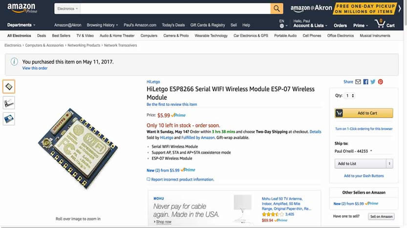
Neil stated that these devices are assembled cards with an integrated antenna. They are readily available on Amazon, and though there is some sort of specification for this device, there are variations between manufacturers including different features and build qualities. Many useful components are packaged together on a mini-board or "module", which can be integrated into a project board via soldering or through connection headers. Cheap enough, I decided I would buy a variety and experiement with them.
The ESP-07 package is a small form factor module which can be hand soldered with difficulty to a 3.3V project board.

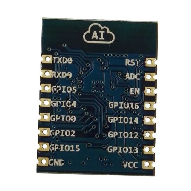
This ESP8266 WIFI module appears to have an antenna jack in the lower left corner, and can be soldered to a pc board of my design. This module requires 3.3V @ 300mA or better, and IS NOT 5 volt tolerant. I found an EAGLE library for ESP8266 which has ESP-07 listed.
This is a great module for Fabacademy while you are developing. Lots of components are stuffed on this development module.
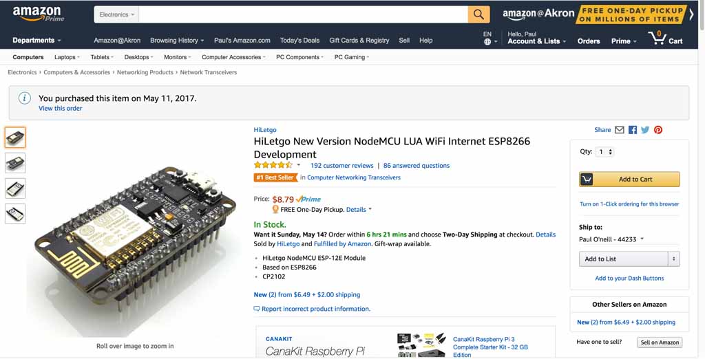
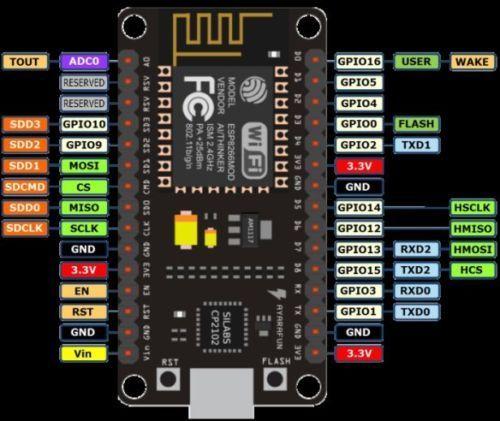
This module is described as an Internet WIFI Development Board Open source Serial Wireless Module. It seems to have many features for a great price, and comes complete with header pins and a micro-USB connector. There is a USB to serial chip on the module. It can be powered through the 5V USB port or through 3.3V to one of the header pins. This module is an "Amica" design, which is a very loose standard. The WIFI is of the 2.4G variety,so if you are in anarea crowded with wifi routers, it may not work too well.
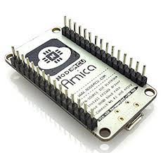
Description:
- ESP8266 CP2102 NodeMCU LUA ESP-12E WIFI Serial Wireless Module
- Built-in Micro-USB, with flash and reset switches, easy to program
- Full I/O port and Wireless 802.11 supported, direct download no need to reset
- Arduino compatible, works great with the latest Arduino IDE/Mongoose IoT/Micropython
- Data download access to the website: http://www.nodemcu.com
ESP8266 is a highly integrated chip designed for the needs of a new connected world. It offers a complete and self-contained Wi-Fi networking solution, allowing it to either host the application or to offload all Wi-Fi networking functions from another application processor.
Instruction & Steps of How to use:
1. Download the Arduino IDE, the latest version.
2. Install the IDE
3. Set up your Arduino IDE as:
Go to File->Preferences and copy the URL below to get the ESP board manager extensions: arduino.esp8266.com/stable/package_esp8266com_index.json
4. Go to Tools > Board > Board Manager> Type "esp8266" and download the Community esp8266 and install.
5. Set up your chip as:
Tools -> Board -> NodeMCU 1.0 (ESP-12E Module)
Tools -> Flash Size -> 4M (3M SPIFFS)
Tools -> CPU Frequency -> 80 Mhz
Tools -> Upload Speed -> 921600
Tools-->Port--> (whatever it is)
6. Download and run the 32 bit flasher exe at Github(Search for nodemcu/nodemcu-flasher/tree/master/ at Github)
github.com/nodemcu/nodemcu-flasher/tree/master/Win32/Release
Or download and run the 64 bit flasher exe at:
github.com/nodemcu/nodemcu-flasher/tree/master/Win64/Release
7. In Arduino IDE, look for the old fashioned Blink program. Load, compile and upload.
8. Go to FILE> EXAMPLES> ESP8266> BLINK, it will start blinking.
Data download access to the website:
http://www.nodemcu.com/index_en.html
Firmware link:
https://github.com/nodemcu/nodemcu-firmware
Similar to the ESP-07, the IFANCY is powered by a pin. It is NOT 5V tolerant and will burnout iof you apply 5V. WIFI antenna is integral to the module. Directly solder chip to your board as if it was a surface mount, with some difficulty.
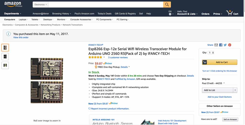
This is a ESP8266 WIFI module has the antenna integral to the module and is designed to be board mounted by soldering and having a ESP-12E layout.
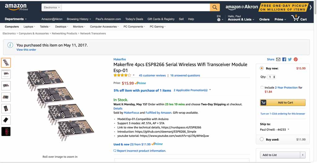
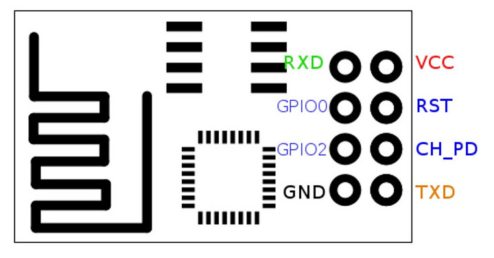
The Makefire is an ESP8266 ESP-01 module with anintegral header,suitable for installing on a breadboard. Integral antenna, 3.3V power, 2.4G Wi-FI.
Bluetooth applications are for where you want to connect a serial device without wires. It is a smaller, simpler module. My first choice is the ESP modules,andthe Bluetooth I considered my backup option. Best to have them on-hand, ready to go. My lab does not currently carry these. After more experience, oneortwo versions of each should be included in the Fablab inventory.
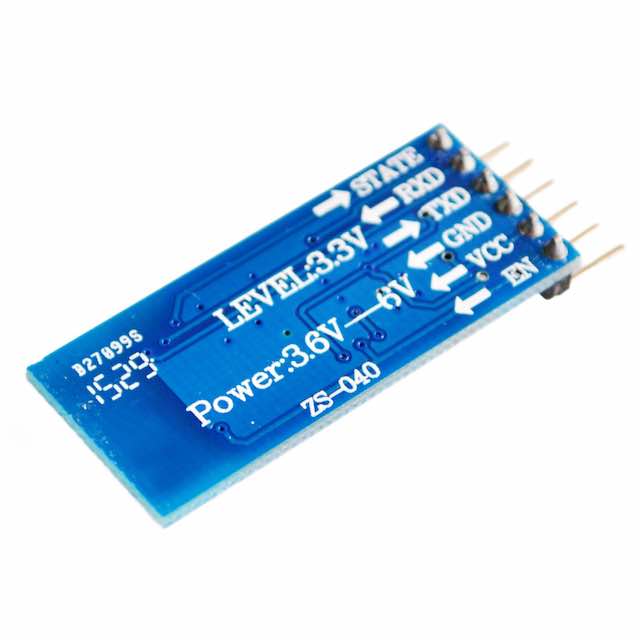
This is a Bluetooth module which includes header pins, which makes it easy to install/change into a project board. It appears to be ready to connect to an FTDI cable.
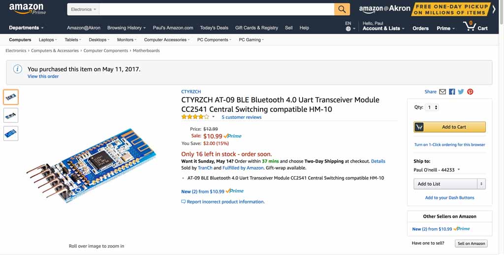
This is a CC2541 Bluetooth module. It states it is "Central Switching compatable HM-10" and AT-09 BLE. Serial UART and 3.3V to 6V. No soldering necessary. Suitable for header connection or breadboard.
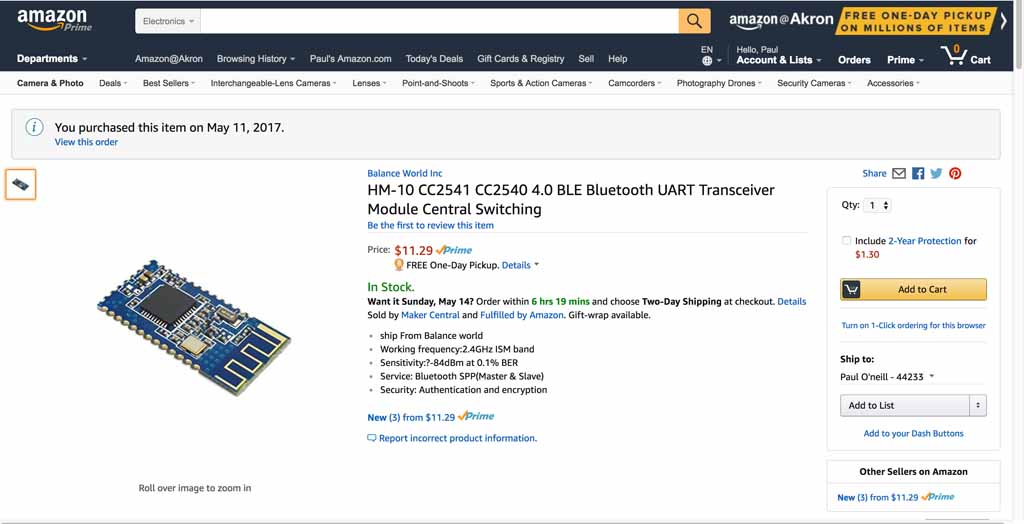
This is a bluetooth modulewhich can be surface mounted and hand-soldered to a project board.
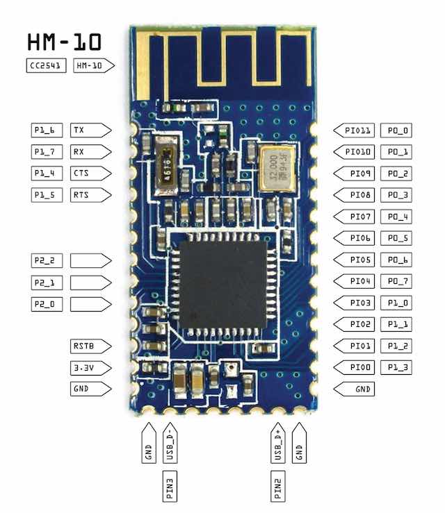
A MIT-CBA tutorial for this module can be found here: http://fab.cba.mit.edu/classes/863.15/doc/tutorials/programming/bluetooth.html
I ordered pairs of everything. Never seen these before, so I tought I would touch and feel at first. I focused on the ESP8266-12E for my "all-in-one" board concept, and the nodeMCU module for the multi-board concept. I also orderded pairs of the BLE modules in case I couldn't figure out the ESP. The sense I got from Neil's lectures and in reviewing prior Fabacademy work with the ESP, that they are difficult. Furthermore, the O2 sensor I was seriously considering was actually a sensor with a built-in processor, communicating via RS232. This was starting to get complicated. When things get complicated, divide and conquor. Break big problems into smaller problems. Small chunks are easier to digest than big ones.
I have to read the data sheets and evaluate what is required to operate these modules. They seem to be orientated to Arduino. The Fabacademy Commercial Board policy seems to allow using commercial boards on shields which are fabbed to demonstrate the shields can network. It is not clear if one Fabduino needs to be built for this weeks project, so I should reach out to my instructor. I am also interested in using serial communication to talk with serial based sensors, which may be used in my final project. I need some clarification from my remote guru if that applies to the weekly assignment. Are the ESP modules commercial boards? Are they soon to be part of the Fablab inventory? I really thought a sensor shield using the nodeMCU made sense for this project.
(id='problems')
I spent time with my instructor, Chris Rohal, reviewing my HelloSolenoid-r8 output board in which I fried the voltage regulator. Chris suspected that my programmer backfed power to the voltage regulator which caused it to malfunction and burn. This can be correctecd by protecting the VR with a diode. I also explained to Chris that the ESP8266 requires 3.3 volts and is NOT 5 volt tolerant; wherein the Tiny44 runs on 5 volts but is 3.3V tolerant. Soon after I designed the HelloSolenoid-r8 board, I realized everything was getting a little crowded, so I planned to solve the problem by communicating from the Tiny44 to the ESP8266 via an available port. I will also build the ESP8266-12e on a separate board with it's own headers which will allow the O2 sensor to be connected through serial RX and TX at 3.3V which is the same as the ESP. I cannot connect my O2 sensor to 5V RS232. It needs to be 3.3V RS232.
I further discussed with my instructor, Chris Rohal, my final project and how I planned on chaining more than one board together, and also the all-in-one board concept. Chris seemed to think I had a good concept, so I proceeded on fabrication. Chris described to me his Final Project which was based on the ATTiny44 and how he barely squeezed by with enough memory. This turned out to be the case with my HelloSolenoid-r13 board as well. In the Arduino environment, I frequently would get warning messages about not ewnough memory for variables, unpredictable results.
My original concept was to utilize the hello-output design from earlier week and morph it into the HelloSolenoid-r13 so it can control and power a solenoid valve. I would also need to open up an input port on the ATTiny44 which would allow connecting it to an Espressif/ESP8266 MCU based board. The ESP board would have the correct RS232 voltage for my sO2 sensor, and have enough memory to communicate with the elaborate string the sensor generates. I decided to name the two boards "hello-solenoid" and "hello-nodeMCU". I ended up designing and making many versions of these boards. I program and tested the boards first with simple LED blink programs, and then I continued on to making connections between the two boards via a breadboard and a regulated power supply.
I dug into the data sheet for the ESP8266 family of processors. There really isn't one standard, and different manufacturers have their own "style" of implementation, so you must be a little careful. I plan on choosing a cetain style, getting familiar with it, and sticking with it.
Files:
Data sheet WIFI Module ESP8266:
(id='design')
The Hello-Solenoid board is a descendant from the project we did on Week 8. This is a better version which addresses some of the failures of the earlier project. Designed using Eagle version 7.70 (Mac).
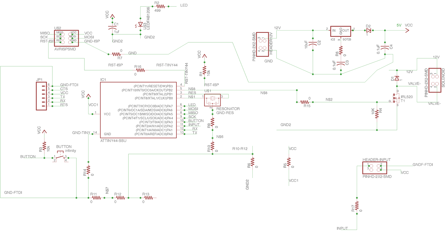
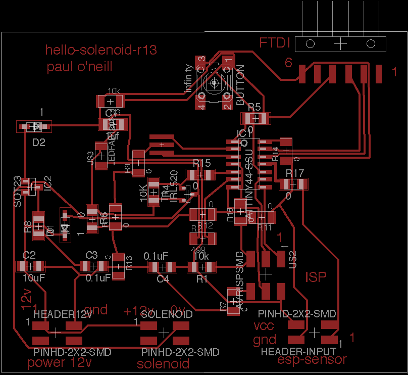
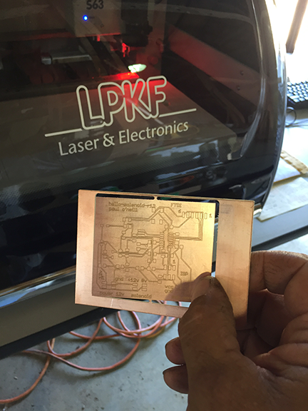
Convert Eagle file to Gerber file and cut on my LPKF board mill.
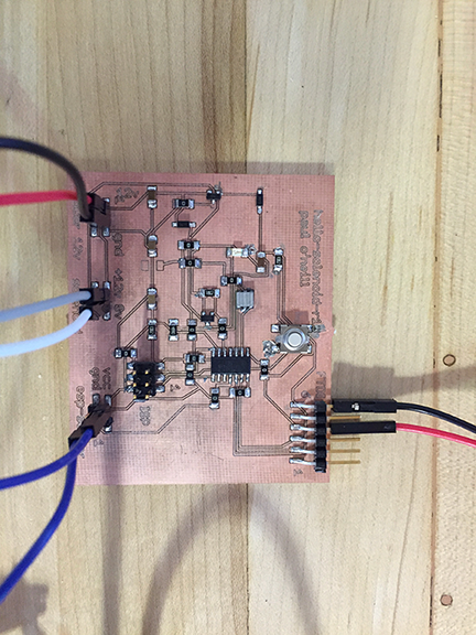
(id='programming')
I adapted this program from one of the example sketches included with the Arduino IDE for my hello-solenopid-r13 board. I added the solenoid to act in parallel to the LED. This board is based on the ATMEL ATTiny44 which is 5 volt based. The solenoid valve is 12 volts. In previous boards, I cooked the voltage regulator because the board was being powered from two sources, which "goofed" up the voltage regulator and caused it to fail. I added diodes to protect the voltage regulator. Nevertheless, I use a programmer which has the ability to power or not power the board. I had good success with the "Sparkfun AVR pocket programmer" available through Digikey, part number 1568-1080-ND for $14.95. I highly recommend it. It is convenient to leave power off and keep debuigging your board without having to worry about frying a voltage regulator. In hindsight, I think it is better to isolate the solenoid power from the electronics. That way there is less risk of damaging laptops/computers. It also reduces risk of "goofing" up a voltage regulator, and allows flexibility of different solenoid coil voltages and power types. Later on, I use a modified version of this to communicate with CBAmods. I originally put the SoftwareSerial module in the code to help troubleshoot. The original example program did not have any serial communication implemented. I like to print what is going on in the program as I develop. Later on, this library module will come in handy when I communicate with CBAmods. The variable ESP identifies the pin which is going to communicate with the ESP8266MCU board which is described later. Even implementing CBAmods into my final project, I think this communication line is still necessary.
---------------------------------------------------------------------------------------------------------------
#include <SoftwareSerial.h>

/*
  HELLO-SOLENOID-ESP

  by Paul O'Neill
  Modified from example in the Arduino IDE.  Contributing authors noted below.

  Turns on an LED on for one second, then off for one second, repeatedly.

  Most Arduinos have an on-board LED you can control. On the UNO, MEGA and ZERO
  it is attached to digital pin 13, on MKR1000 on pin 6. LED_BUILTIN is set to
  the correct LED pin independent of which board is used.
  If you want to know what pin the on-board LED is connected to on your Arduino model, check
  the Technical Specs of your board  at https://www.arduino.cc/en/Main/Products

  This example code is in the public domain.

  modified 8 May 2014
  by Scott Fitzgerald

  modified 2 Sep 2016
  by Arturo Guadalupi

  modified 8 Sep 2016
  by Colby Newman
*/


const int LED = 7;  //TINY44 PA7
const int SOLENOID = 8;     //TINY44 PB2, IDE 8, pin 5
const int ESP = 2;  //TINY44 PA2, IDE 2, pin 11
const int BUTTON = 3;     //TINY44 button connected to PA3, IDE 3, pin 10


// the setup function runs once when you press reset or power the board
void setup() {
  // initialize digital pin LED_BUILTIN as an output.

  pinMode(LED, OUTPUT);
  pinMode(SOLENOID, OUTPUT);
  pinMode(ESP, INPUT);
  pinMode(BUTTON, INPUT);

  //  Serial.begin(9600);
}

// the loop function runs over and over again forever
void loop() {

  int ESPValue = digitalRead(ESP);
  //  Serial.println(ESPValue);
  if (ESPValue > 0) {
    delay(1);                   // delay added to debounce pin
    digitalWrite(LED, HIGH);
    //digitalWrite(INPUTLINE, HIGH);
    digitalWrite(SOLENOID, HIGH);
  } else {
    digitalWrite(LED, LOW);    // turn the LED off by making the voltage LOW
    digitalWrite(SOLENOID, LOW);

    /*
       The code below left in for troubleshooting purposes.

      digitalWrite(LED, HIGH);   // turn the LED on (HIGH is the voltage level)
      //  digitalWrite(INPUTLINE, HIGH);
      digitalWrite(SOLENOID, HIGH);
      delay(2500);                       // wait for 2500 millseconds
      digitalWrite(LED, LOW);    // turn the LED off by making the voltage LOW
      //  digitalWrite(INPUTLINE, LOW);
      digitalWrite(SOLENOID, LOW);
      delay(1000);                       // wait for 1000 milliseconds

    */
  }
}
---------------------------------------------------------------------------------------------------------------
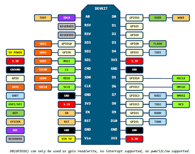
The purpose of the Hello-nodeMCU shield is to provide a platform for connecting the ESP8266-12E to both the Hello-Solenoid-r13 board as well as the Luminox O2 sensor. It arranges the correct voltage for the RS232 Serial for the O2 sensor with little chance of failure. Not all MCU's are built the same. This is the pinout for the "Amica" model I am using:
Nexy, I used Eagle to design a board/shield that the developer module could connect to. This shield is designed to keep my O2 sensor seperated from the ATTiny board which could cause damage. The ATTiny board, as designed, has 12VDC applied to it. The O2 sensor is an expensive unit. I don't want to risk damaging it. I do use a 6 pin header which is like a FTDI connector. However, I have not tested it yet. The 'Amica' has a built-in micro-USB connector which is more than adequate to power and communicate. The 'Amica' has two (2) serial "ports", so this might be something to consider in the next revision.
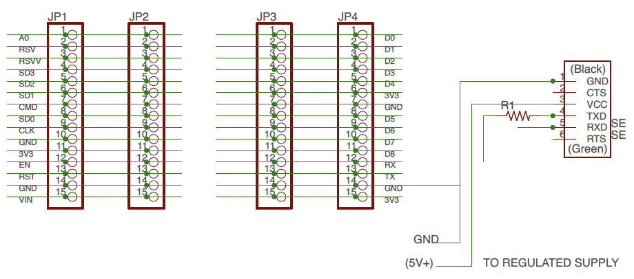
Note: Resistor R1 is a zero-ohm jumper.
(id='files')
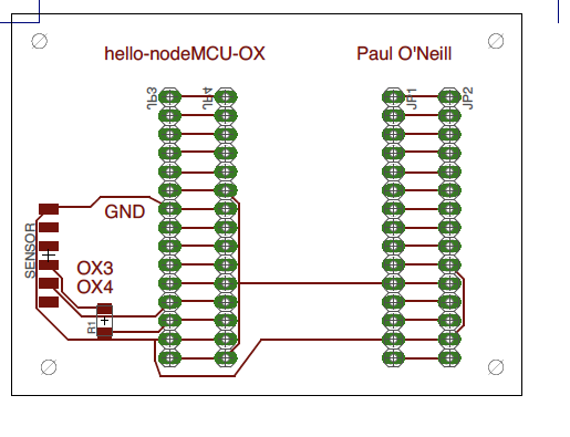
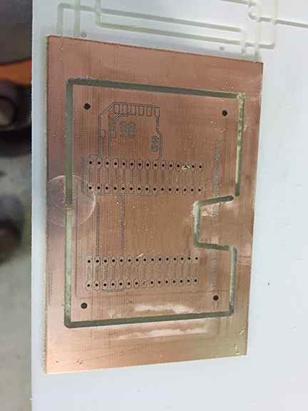
Board engraved and drilled on LPKF mill.
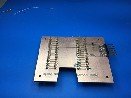
Header pins inserted into drilled holes and soldered. You need 0.80 mm
drill bit to get close tolerance hole for solder to bridge between pin and board.
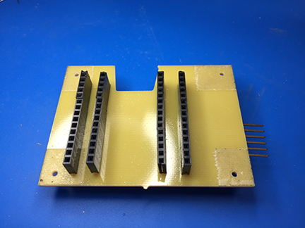
These type of header pins not found in FabLab inventory. You can find them
in the Adafruit git repository for Eagle CAD.
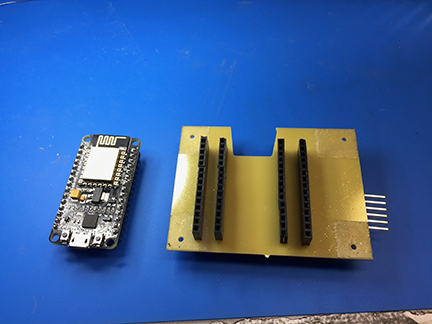
The nodeMCU "Amica" before insertion intop the shield. Other implementations of nodeMCU will probably work. Check pinouts on data sheet! Remember, the O2 sensor must be 3.3V RS232.
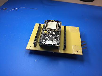
The ESP8266-12 nodeMCU installed into the shield. These can be bought for less than $10 in single quantity, including shipping, from Amazon.
I wrote this program to demonstrate an application program that utilizes the WiFi feature of the ESP8266 and runs on the internet and controls the hello-nodeMCU board, which yet controls the solenoid board. The hardest part here is mapping out physical pins to GPIO pins on the ESP8266. This is why I made a shield with a couple of extra headers, so I could experiment with the different GPIO available on the ESP8266 module. First thing is to see if the WiFi works. I always like to divide and conquor when I troubleshoot. I take large problems and break them down into smaller pieces. Then pile them back together using spiral development. I will be adding to this program later in the Final Project development. Here, I get the serial communication working and dialog to CBAmods established.
Program sketch esp8266-webserver-graphical-luminox-o2-solenoid-test (cut and paste into your Arduino IDE):
---------------------------------------------------------------------------------------------------------------
/*
  ESP8266 Server program to read Luminox O2 sensor.

  By: Paul O'Neill

  (C) Copyright 2017 by Paul X. O'Neill, All rights reserved.

  Receives from software serial port, sends to hardware serial port.
   RX is digital pin 10 (connect to TX of level shifter: pin B1)
   TX is digital pin 11 (connect to RX of level shifter: pin B2)
  The code was written for hello-nodeMCU and Arduino IDE ver. 1.6.1.

  Adapted from an example program called WiFiWebClient
  included in the Arduino IDE written by dlf (Metodo2 srl)
  and modified by Tom Igoe

*/


#include <ESP8266WiFi.h>
#include <ESP8266WebServer.h>

const char* ssid = "wf-b";
const char* password = "2627f68597";

String form = "<form action='led'><input type='radio' name='state' value='0' checked>On<input type='radio' name='state' value='1'>Off<input type='submit' value='Submit'></form>";

String imagepage = "<img src='/led.png'>";

// This is a png file (led.png)
const char image[] = {
  0x89, 0x50, 0x4e, 0x47, 0x0d, 0x0a, 0x1a, 0x0a, 0x00, 0x00, 0x00, 0x0d, 0x49, 0x48, 0x44, 0x52,
  0x00, 0x00, 0x00, 0x10, 0x00, 0x00, 0x00, 0x10, 0x08, 0x02, 0x00, 0x00, 0x00, 0x90, 0x91, 0x68,
  0x36, 0x00, 0x00, 0x00, 0x01, 0x73, 0x52, 0x47, 0x42, 0x00, 0xae, 0xce, 0x1c, 0xe9, 0x00, 0x00,
  0x00, 0x04, 0x67, 0x41, 0x4d, 0x41, 0x00, 0x00, 0xb1, 0x8f, 0x0b, 0xfc, 0x61, 0x05, 0x00, 0x00,
  0x00, 0x20, 0x63, 0x48, 0x52, 0x4d, 0x00, 0x00, 0x7a, 0x26, 0x00, 0x00, 0x80, 0x84, 0x00, 0x00,
  0xfa, 0x00, 0x00, 0x00, 0x80, 0xe8, 0x00, 0x00, 0x75, 0x30, 0x00, 0x00, 0xea, 0x60, 0x00, 0x00,
  0x3a, 0x98, 0x00, 0x00, 0x17, 0x70, 0x9c, 0xba, 0x51, 0x3c, 0x00, 0x00, 0x00, 0x18, 0x74, 0x45,
  0x58, 0x74, 0x53, 0x6f, 0x66, 0x74, 0x77, 0x61, 0x72, 0x65, 0x00, 0x50, 0x61, 0x69, 0x6e, 0x74,
  0x2e, 0x4e, 0x45, 0x54, 0x20, 0x76, 0x33, 0x2e, 0x33, 0x36, 0xa9, 0xe7, 0xe2, 0x25, 0x00, 0x00,
  0x00, 0x57, 0x49, 0x44, 0x41, 0x54, 0x38, 0x4f, 0x95, 0x52, 0x5b, 0x0a, 0x00, 0x30, 0x08, 0x6a,
  0xf7, 0x3f, 0xf4, 0x1e, 0x14, 0x4d, 0x6a, 0x30, 0x8d, 0x7d, 0x0d, 0x45, 0x2d, 0x87, 0xd9, 0x34,
  0x71, 0x36, 0x41, 0x7a, 0x81, 0x76, 0x95, 0xc2, 0xec, 0x3f, 0xc7, 0x8e, 0x83, 0x72, 0x90, 0x43,
  0x11, 0x10, 0xc4, 0x12, 0x50, 0xb6, 0xc7, 0xab, 0x96, 0xd0, 0xdb, 0x5b, 0x41, 0x5c, 0x6a, 0x0b,
  0xfd, 0x57, 0x28, 0x5b, 0xc2, 0xfd, 0xb2, 0xa1, 0x33, 0x28, 0x45, 0xd0, 0xee, 0x20, 0x5c, 0x9a,
  0xaf, 0x93, 0xd6, 0xbc, 0xdb, 0x25, 0x56, 0x61, 0x01, 0x17, 0x12, 0xae, 0x53, 0x3e, 0x66, 0x32,
  0xba, 0x00, 0x00, 0x00, 0x00, 0x49, 0x45, 0x4e, 0x44, 0xae, 0x42, 0x60, 0x82
};

// HTTP server will listen at port 80
ESP8266WebServer server(80);

const int solenoid = 16;  //ESP-12 pin1, D0, GPIO 16
const int led = 4;        //ESP-12 pin3, D2, GPIO 4

void handle_adc() {
  float val = analogRead(0);
  server.send(200, "text/plain", String(val));
}

void handle_led() {
  // get the value of request argument "state" and convert it to an int
  int state = server.arg("state").toInt();

  digitalWrite(led, state);
  digitalWrite(solenoid, state);
  server.send(200, "text/plain", String("LED is now ") + ((state) ? "off" : "on"));
}

void handle_image() {
  server.send(200, "image/png", "");
  WiFiClient client = server.client();
  client.write(image, sizeof(image));
}

void handle_webpage_with_image() {
  server.send(200, "text/html", imagepage);
}

void setup(void) {
  Serial.begin(9600);
  Serial.println("");
  pinMode(led, OUTPUT);
  pinMode(solenoid, OUTPUT);

  // Connect to WiFi network
  WiFi.begin(ssid, password);

  // Wait for connection
  while (WiFi.status() != WL_CONNECTED) {
    delay(500);
    Serial.print("-SOLENOID TEST-");
    digitalWrite(solenoid, HIGH);   // turn the SOLENOID on (HIGH is the voltage level)
    delay(1000);                       // wait for a second
    digitalWrite(solenoid, LOW);    // turn the SOLENOID off by making the voltage LOW
    delay(1000);                       // wait for a second
    digitalWrite(solenoid, HIGH);   // turn the SOLENOID on (HIGH is the voltage level)
    delay(1000);                       // wait for a second
    digitalWrite(solenoid, LOW);    // turn the SOLENOID off by making the voltage LOW
    delay(1000);                       // wait for a second
    digitalWrite(solenoid, HIGH);   // turn the SOLENOID on (HIGH is the voltage level)
    delay(1000);                       // wait for a second
    digitalWrite(solenoid, LOW);    // turn the SOLENOID off by making the voltage LOW
    delay(1000);                       // wait for a second
  }
  Serial.println("");
  Serial.print("Connected to ");
  Serial.println(ssid);
  Serial.print("IP address: ");
  Serial.println(WiFi.localIP());

  // Set up the endpoints for HTTP server
  //
  // Endpoints can be written as inline functions:
  server.on("/", []() {
    server.send(200, "text/html", form);
  });

  // And as regular external functions:
  server.on("/adc", handle_adc);
  server.on("/led", handle_led);
  server.on("/led.png", handle_image);
  server.on("/showled", handle_webpage_with_image);

  // Start the server
  server.begin();
  Serial.println("HTTP server started");
}

void loop(void) {
  // check for incomming client connections frequently in the main loop:
  server.handleClient();
}
---------------------------------------------------------------------------------------------------------------
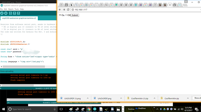
Screenshot of client page. The server is located at local IP address 192.168.1.117 and the solenoid is ion the ON state.
Video of the above program running. First half I run the program from a laptop, addressing 192.168.1.226. Then I use my iPhone to access the same IP address to toggle the output pin on the device. The multimeter on the left represents a LED, and the multimeter on the right represents the signal going to the solenoid board.
Video on Vimeo: https://vimeo.com/274556472
I continued a little further and did some work with CBAmods. The more I use it, the more I like it. The nice thing about CBAmods is that it works on an IP infrastructure which is already in place. However, as a prerequisite, you must have a CBAmods toolchain set up properly. This can be done in Linux, Windows or Mac. Probably easiest on Linux. Read my Week14 page on how I set up my toolchain.
The first thing I did is set up my fabbed board to do something. The following program SoftwareSerialStream-hello-solenoid-input-r13-to-mods sets up serial communication using the RX,TX combination of 3 and 4 (ATTiny default). The program monitors the Button on 7. When pressed, sets the LED to High, otherwise low, with debouncing. The program reports via the serial lines, to CBAmods, a 1 for pressed, or a 0 for not pressed. I did read that ATTiny without hardware UART is not too reliable, can only do input, or output, but not both at the same time. The program compiles with no warnings, but is close to the memory limit.
----------------------------------------------------------------------------------
/*
NAME: SoftwareSerialStream-hello-solenoid-r13
by Paul X. O'Neill on June 10, 2018
for use as a debugging tool when
troubleshooting serial communications between a board and a laptop, especially
with MIT Center for Bits and Atoms mods
This work may be reproduced, modified, distributed, performed, and
displayed for any purpose, but must acknowledge the author.
Copyright is retained and must be preserved. The work is
provided as is; no warranty is provided, and users accept all
liability.
*/
#include <SoftwareSerial.h>
const int LED = 7; // Built-in LED 13, make 7 when using hello-world board
const int DELAYTIME = 250; // delay milliseconds
const int max = 10; // Maximum times to add
const int min = 0; // minimum value of count
int count = 0; // initialize the counter to zero
const int baudrate = 9600;
// solenoid specific settings
//const int SOLENOID = 8; //TINY44 PB2, IDE 8, pin 5
//const int ESP = 2; //TINY44 PA2, IDE 2, pin 11
const int BUTTON = 3; //TINY44 button connected to PA3, IDE 3, pin 10
bool BUTTONvalue = false;
int x = 0;
bool direction = true; // flag for which direction to count. true=up false=down
SoftwareSerial mySerial(3, 4); // RX, TX, 3 and 4 on ATTiny, 10,11 on ESP
// the setup function runs once when you press reset or power the board
void setup() {
// initialize digital pin LED_BUILTIN as an output.
pinMode(LED, OUTPUT);
// pinMode(SOLENOID, OUTPUT);
// pinMode(ESP, INPUT);
pinMode(BUTTON, INPUT);
Serial.begin(baudrate);
// Serial.println(baudrate);
// set the data rate for the SoftwareSerial port
mySerial.begin(baudrate);
}
void loop() { // run over and over
for (int x = min; x < max; x++)
{
// Serial.print(x);
BUTTONvalue = digitalRead(BUTTON);
if (BUTTONvalue == LOW) {
Serial.println("1");
digitalWrite(LED, HIGH);
} else {
Serial.println("0");
digitalWrite(LED, LOW);
}
}
// switch is pressed - pullup keeps pin high normally
delay(DELAYTIME); // delay to debounce switch
}
----------------------------------------------------------------------------------
I performed the Arduino IDE on a Windows 10 machine, and CBAmods on an Apple Mac Laptop with Xcode installed.
I used the ISP port and the Sparkfun AVR programmer to load this program. The programmer was set to power the board.
You cannot use the FTDI port to load the software on this board. You must use the 6-pin ISP. Once the program is loaded, remove the ISP cable, and connect the
board to a FTDI/USB cable. If on a Windows 10 machine, use Device Manager to determine the COM port for the cable. From the Arduino
IDE, run Port Monitor and change the COM port to this device. Set the baud rate at 9600 and look for a readout. If none, switch baud
rates until you get legible readout.
Next, set up the Mac so that it is running a webserver and a serialserver for each board you are connecting. Use the procedures outlined
in Week14 on how to do this.
Next, run Firefox Browser (Chrome doesn't work) from your local CBAmods directory. Put in webadress 127.0.0.1:8080 and you should see the
CBA icon. At this point, I use an Arduino which I set up in Week14 to check my connection. If you don't do this, you can drive yourself
crazy..
Right click and program the following nodes:
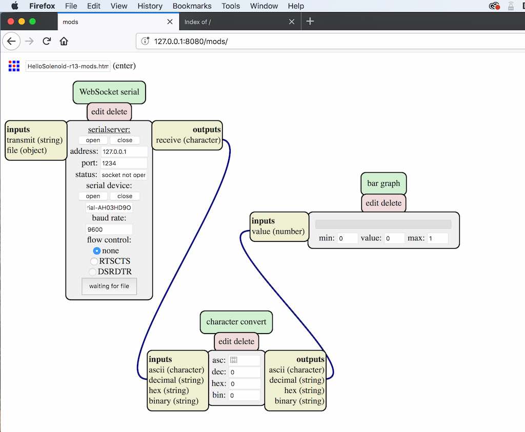 Next, unplug the fabbed board from the Windows machine and plug into the Mac. In websocket serial, you enter address 127.0.0.1, port 1234,
serial-port-name, and baud rate. Click open and see if it works. If it doesn't, recheck your terminal window where you are running SerialServer.
(id='mods-video)
Video of what it looks like: https://vimeo.com/274414672
So, the above model is a simple network. There is a lot of debate within Fabacademy as to what constitutes a network, and what are the exceptions. What is a network? It's a very large topic, and different people have different opinions about it. Neil has discussed in his Communications and Networking lecture the OSI model. The OSI model came about around 1982, and it is somewhat of a standard, though not strictly followed. However, it's core components might be useful for describing those areas used in Fabacademy, and explaining what is available for use within CBAmods, and help explain my example for this week which I feel works with CBAmods and works with the principal of spiral development.
I would like to refer to a chart that I found on Wikipedia at this link: https://en.wikipedia.org/wiki/OSI_model. As of June 2018, this page has a pretty decent description of the 7-layer OSI model (there is an eighth layer, maybe...). The chart below is right from that page:
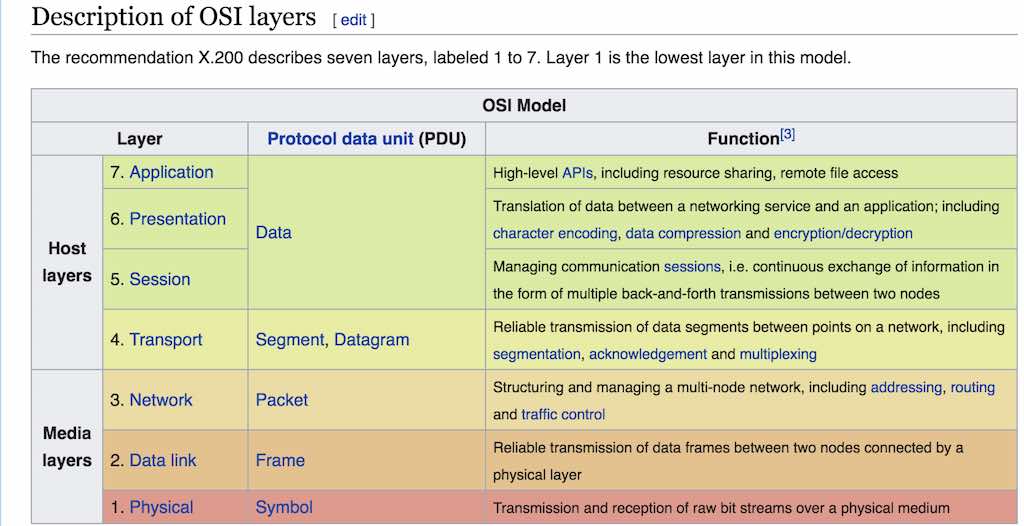
With MCU's, we are mosty dealing with the physical layer. This can be I2C, FTDI, RS-232. My previous example utilized RS232 via a UART on an ESP8266 development module which was integrated into a fabbed board. My following example utilizes three board. Two boards are ATTiny44 based fabbed boards, with resonators, which are described earlier in this page. The third is a commercial Arduino Board. I did attempt to use my hello-world board fabbed earlier in the course. It does not work reliably, I think due to the fact that it has no resonator or crystal. Thus, the hello-world board does not make it past layer 1. The rest make it to layer 2, the data link.
Layer 2, the data link. I believe I am utilizing SLIP (Serial Line Internet Protocol) when I run the terminal command node serialserver.js ::ffff:127.0.0.1 1234. In simple terms, the serialserver program converts the data from layer 1 into packets usable by internet protocol. Notice some of the parameters in the command. 127.0.0.1 is the IP address of my Mac laptop where I ran this program. In the following example, I ran a terminal window for each card, opening a thread for each card to talk to mods. Each card will be communicating to the mods webserver located at 127.0.0.1 port 8080 (bottom left window). The boards each have unique ports, that being 1234, 2345, and 3456. Those numbers will be really important later when we start to write our mods program. In order for the mods program to work, we need to build the network first:
I connect each board to my laptop. The fabbed boards I use a FTDI cable. The commercial Arduino, I use a micro-USB cable. In Linux, each serial connection is treated as a file. So, in order to identify each board, I open a terminal window and type ls /dev/tty.*
This producesw a list of files connected to my laptop, which happen to include bluetooth devices, serial devices, my cell phone, etc.... Each board has a unique name. Some of the Fabacademy instructors insist that each board must have an address. This happens here on layer 2. In my case, they are automatically assigned. The address of my boards, in this example, are:
Each board is a modified version of what I described during my demo of CBAmods in week14.
I uploaded a video of
all the boards running their test patterns. You can view it here: https://vimeo.com/276858897. You can see that each terminal screen is divided in half. After you execute your command, you press COMMAND-D and you getr a dual display. To manually terminate a screen, you need to type COMMAND-A - K and then answer Y for yes. In the video, I disconnect and reconnect each board. Interestingly, the fabbed boards automatically restart whereas the commercial board requires that I retype this command:
Ok, this is where we get a webserver running. We start another Linux thread.... I mean terminal window.... or do I mean session. I suppose the correct term depends on who you are taking with. You don't run the webserver until you are in the mods directory. I explained all of this in my week14 mods demo.
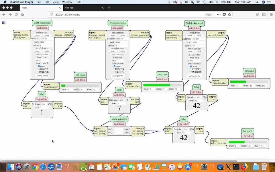
I have a nice video of all of this running. You can view it by following this link: https://vimeo.com/276857298
The program that does this: boards-on-mods.html
At this point, al you need to do is point and shoot with CBAmods to access the remaining layers. That is the beauty of CBAmods. It kends itself to the distributed model of networking. For more information about the application layer, please read this guide on how to set up websockets using javascript: https://itp.nyu.edu/physcomp/labs/labs-serial-communication/lab-serial-communication-with-node-js/
For a nice example of communicating via wifi with an ESP8266 module, please check out Gary Zhexi Zhang's page at http://fab.cba.mit.edu/classes/863.17/Architecture/people/garyz/12.html
For more information about the websocket protocol standard, follow this link: https://tools.ietf.org/html/rfc6455. It starts with this:
The WebSocket Protocol enables two-way communication between a client running untrusted code in a controlled environment to a remote host that has opted-in to communications from that code. The security model used for this is the origin-based security model commonly used by web browsers. The protocol consists of an opening handshake followed by basic message framing, layered over TCP. The goal of this technology is to provide a mechanism for browser-based applications that need two-way communication with servers that does not rely on opening multiple HTTP connections (e.g., using XMLHttpRequest or <iframe>s and long polling).
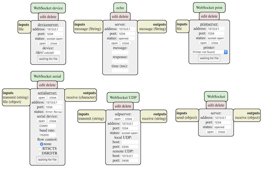
There are six websockets available in CBAmods. My best understanding of what they are for:
I have seen that students have been hacking their own versions of CBAmods. I am looking forward to someone at MIT setting up a fork of CBAmods where people can contribute and share, and worthy hacks are added to the core mods.

This work is licensed under a Creative Commons Attribution-NonCommercial-NoDerivatives 4.0 International License.