Mechanical Design.
CNC Machine
The objective of this week is to design and assemble the mechanical part of a CNC machine.
Among all the possible designs that exist, we will design a machine whose X and Y axes move by means of a transmission of pulley and belt, while the z axis will move by means of a worm.
For a better movement we will also use some bearings to facilitate the work of the motors step by step, since these will oversee carrying out the movement.
With the help of the director of the CIT we get all the necessary parts to be able to make the machine
 Between Danny, Italo and I will design the missing pieces for the correct functioning, even when performing the tests, we can modify some piece for its better functioning.
Personal contribution
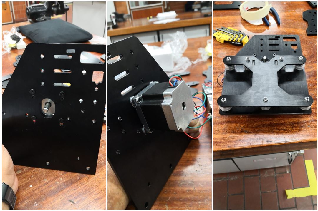
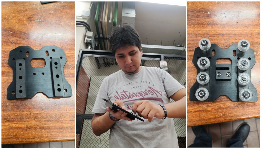
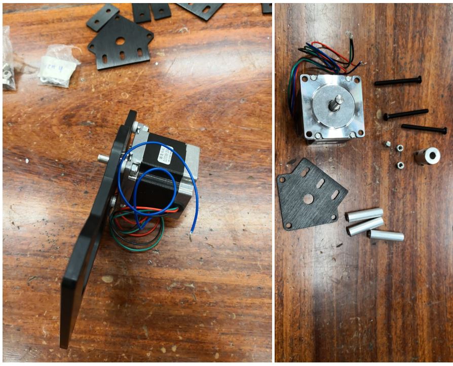
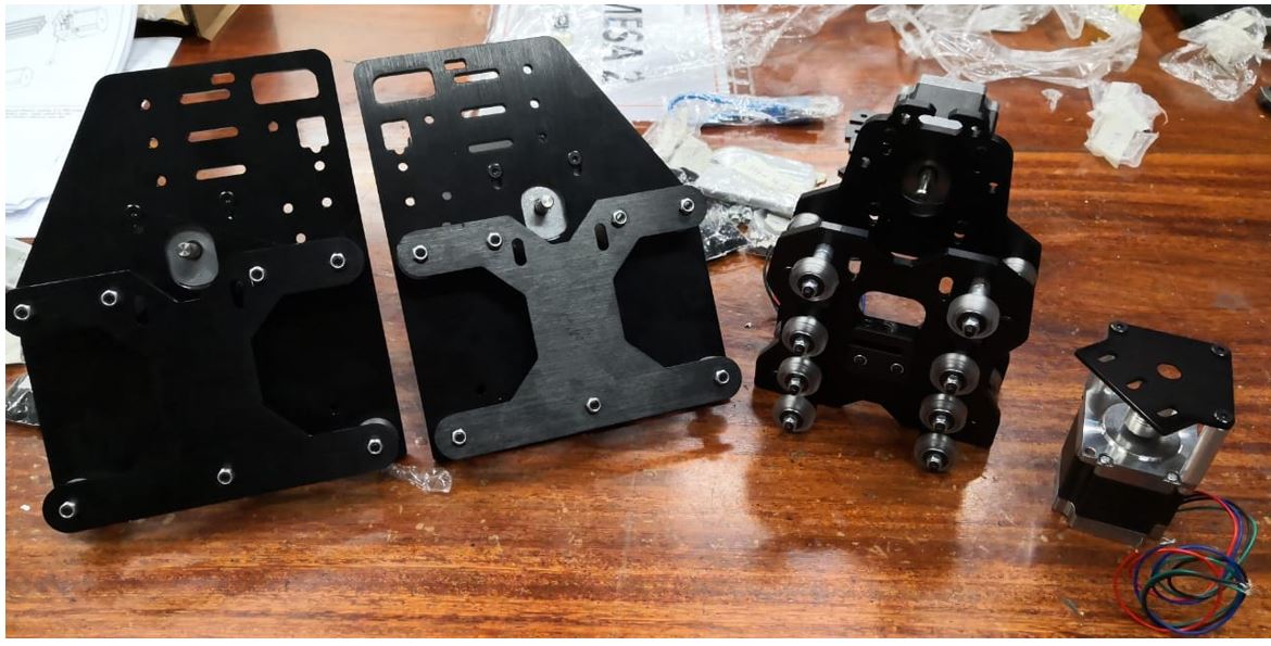
In my personal contribution I made the assembly of the mechanical parts of the machine, including the stepper motors. Here are some pictures of the assembly of the parts.
Here is the X plate.
 Here is the first part of Y plate.
 Here is the second part of Y plate and pieces of Z part.
 Finally, here are all the parts that I assemble.
 Additionally, I am designing a board using the atmega328 to connect the CNC software and the drivers for the correct operation of the machine.
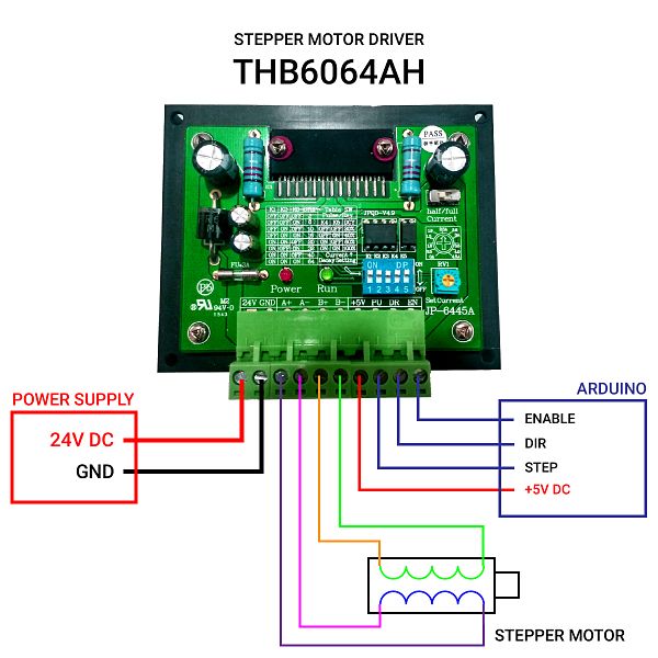
Source: https://naylampmechatronics.com/drivers/268-driver-pap-thb6064ah-4a.html
Since only the mechanical design is requested, I only made the schematic of the circuit I relied on the design of the Arduino CNC shield.
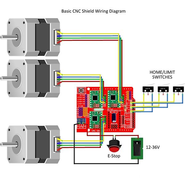
Source: http://makercommunity.info/photo/view/23/latest
This design is intended to be used for the final operation of the machine. All information about the machine and its demonstration of operation can be seen on the page of the laboratory.To see all the documentation of the group work, you can visit the CIT page.
Download
You can download this files Here:
Schematic.
