.png)
Hi! Welcome to Week 12
This week’s assignment was add an output device to a microcontroller board I've designed, and program it to do something!
This week’s assignment was add an output device to a microcontroller board I've designed, and program it to do something!
For this week, I am going to make a story board in the shape of a box, that is going to be controlled by a button that will cause the stepper motor to rotate, and I will also use lights that will be placed in the box, and will cast it’s shadow on a wall. I designed the box using festi, I simply added the dimensions that I would want for my box and the type of joint I want and the website generated the 2d plans for the box ready for cut, you can download my box from here . Since I do not have CorelDraw on my laptop, I prepared the file using InkScape, with was a bit tricky but this tutorial helped me maneuver with the program, and I added the drawings I want on each side, Here are the files for the drawings, Which were made by my sister Diana Habashneh. Next, I added a circle in the center of the sides, where the rod will pass through, and I then laser cut the plans.
So now back to CorelDraw, I made the dimension of the drawings Hairline, and then proceeded to cut it using the Laser machine. After I finished this par, I drew the gear and the base, and again cut the using the laser machine.
After this part, I prepared the board that will be used along with the device. I wanted the device to be able to operate anywhere and so I added a micro USB port.
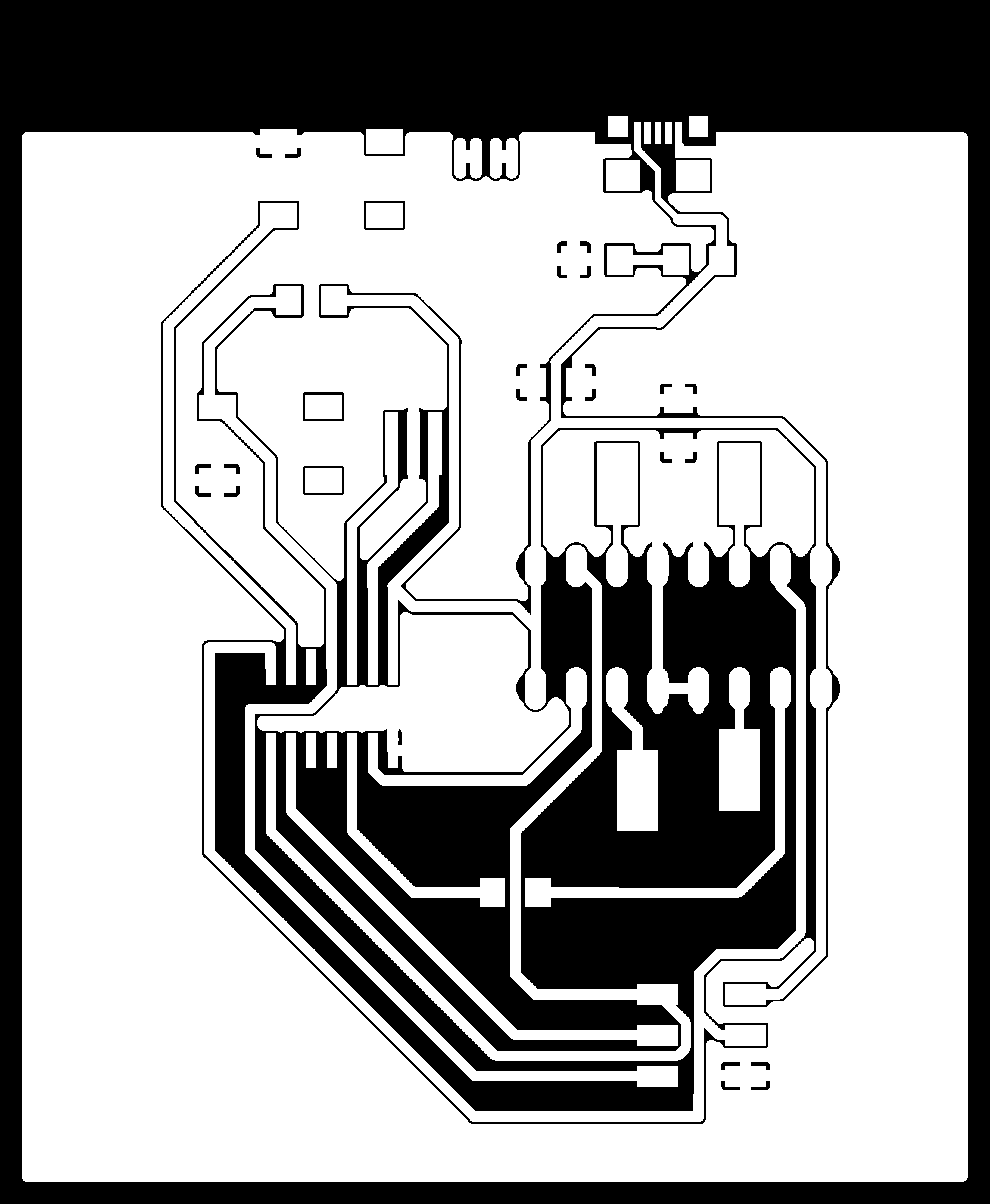
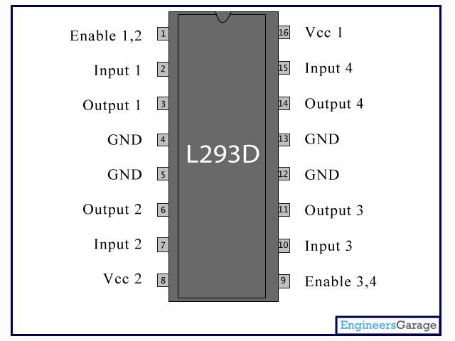
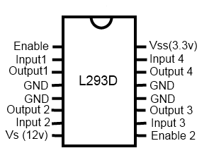
I assembled the pieces together, and now I had to think on the rotating mechanism, and the electronic board. Here’s the schematics, and the board. Also, since I was using a stepper motor this week, I checked the data sheet, and also added an H bridge driver to the board and connected it according to its pinout.
Here you can download the traces, holes, and outline.

I soldered all the electronic parts to the board except for the motor, but it turned out after testing the board that I had burned the H bridge. I removed it and the soldered a pins extension, this way I could avoid burning it again as it's a sensitive part.
Before programming my board, I had tested this program using an Arduino board and bread board just to ckeck if my code did what I wanted it to do, this is the code I used:
#include  <Stepper.h>

const int stepsPerRevolution = 48;
int PushButton = 5;
// initialize the stepper library on pins 8 through 11:
Stepper myStepper(stepsPerRevolution, 8, 9, 10, 11);

void setup() {
  pinMode (PushButton, INPUT_PULLUP);
  myStepper.setSpeed(30);

  Serial.begin(9600);
}

void loop() {
  int readPushButton= digitalRead (PushButton);
if (readPushButton == 0) {
  Serial.println("clockwise");
  myStepper.step(stepsPerRevolution/6);
  delay(500);

}
}