.png)
Hi! Welcome to Week 8
This week’s assignment was to make something big!
This week’s assignment was to make something big!
I have been thinking about what I want to make in this week almost since I started the FabAcademy. This week gives a large degree of freedom in designing, but after having my mind blocked for around 6 days, I realized that having less constrains kind of makes it harder. I lost a lot of time while trying to make something original and unique, but after designing it I was pleased with the results.
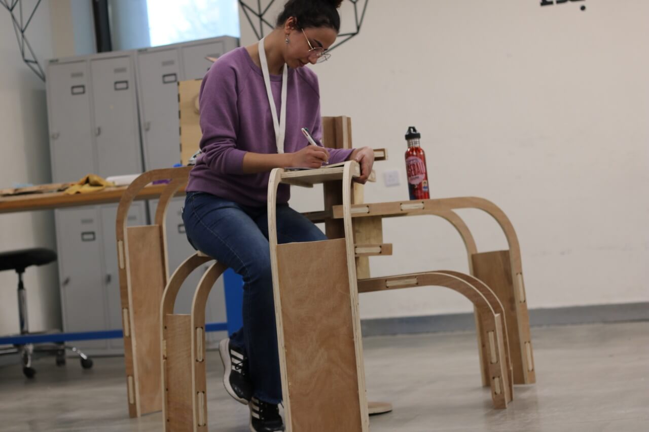
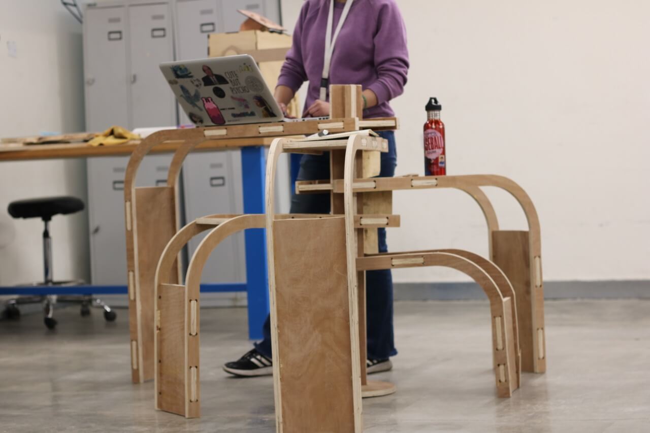
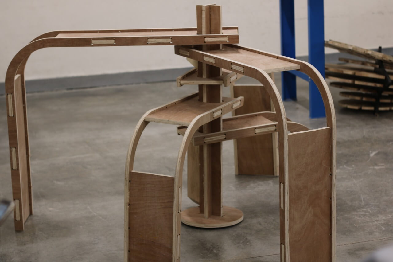
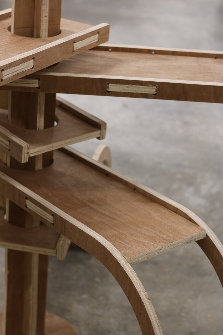
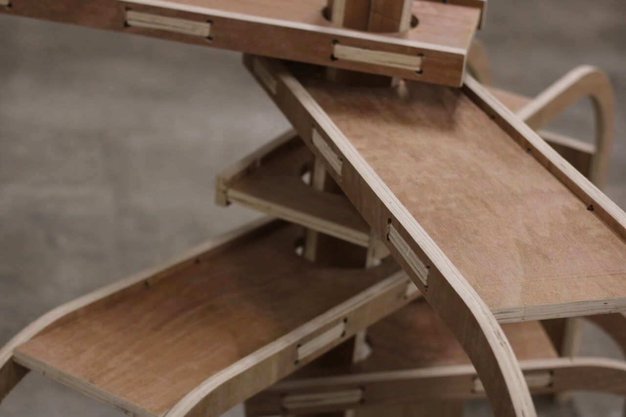
So, I decided to make a table/chair/stairs stand, that can be used in several ways (I’m a fan of smart furniture). This piece consists of a vertical and a horizontal wooden pieces, connected together through a living hinge, with a hole on the horizontal side to slide around a fixed stand. These pieces will come in different sizes so that the stand will have 5 layers.
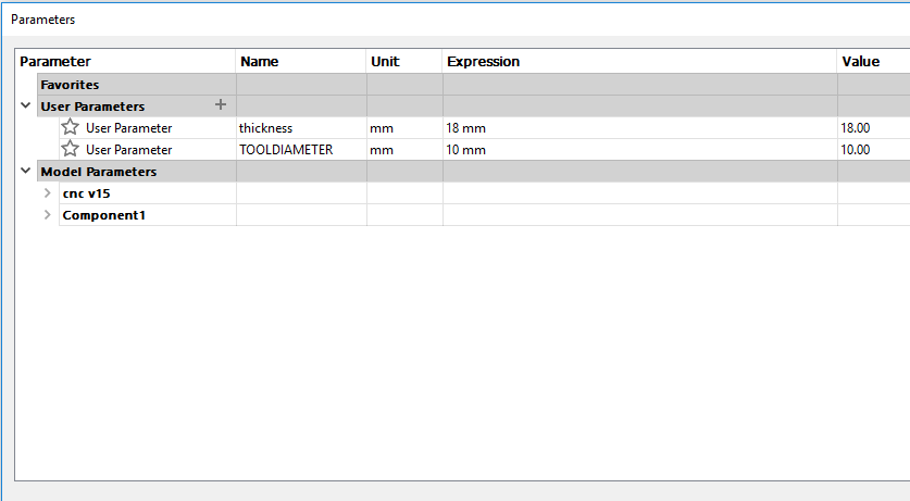
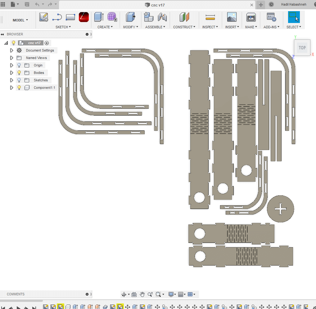
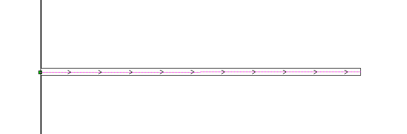
I started designing the “thing” (I need to come up with a name for it) on Fusion360. That was relatively easy as it was basically drawing straight lines, arcs, offsets and mirrors. I sat the holes on the bases of the joint to a parameter (which can in handy later on) in order to change it fast if I found the hole size to be too big or too small. I then extruded the parts, and to get the outline in 2d, I selected the bodies I wanted to outline, then head to sketch, project, project, and a pink outline is generated. form the menu on the left, I saved the generated sketch as DXF. here are the files of the and the first board and the second board, and you can also download the original file.
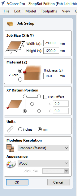
Now to prepare the job, I started using vCarve, which was my first time using it. When I added a new file, I got this window, where I inserted the dimensions of the plywood board I’m using, but I added 4 and 2 cms allowance, so that when the cutting tool is working it won’t hit any fixing nails that might damage the head, also, I sat the Datum Position, which is where the spindle is in accordance to the XY axis.
then, I selected the parts that I want to be cut from the inside together, as well as the parts that I want to be cut from outside the traces and on them.
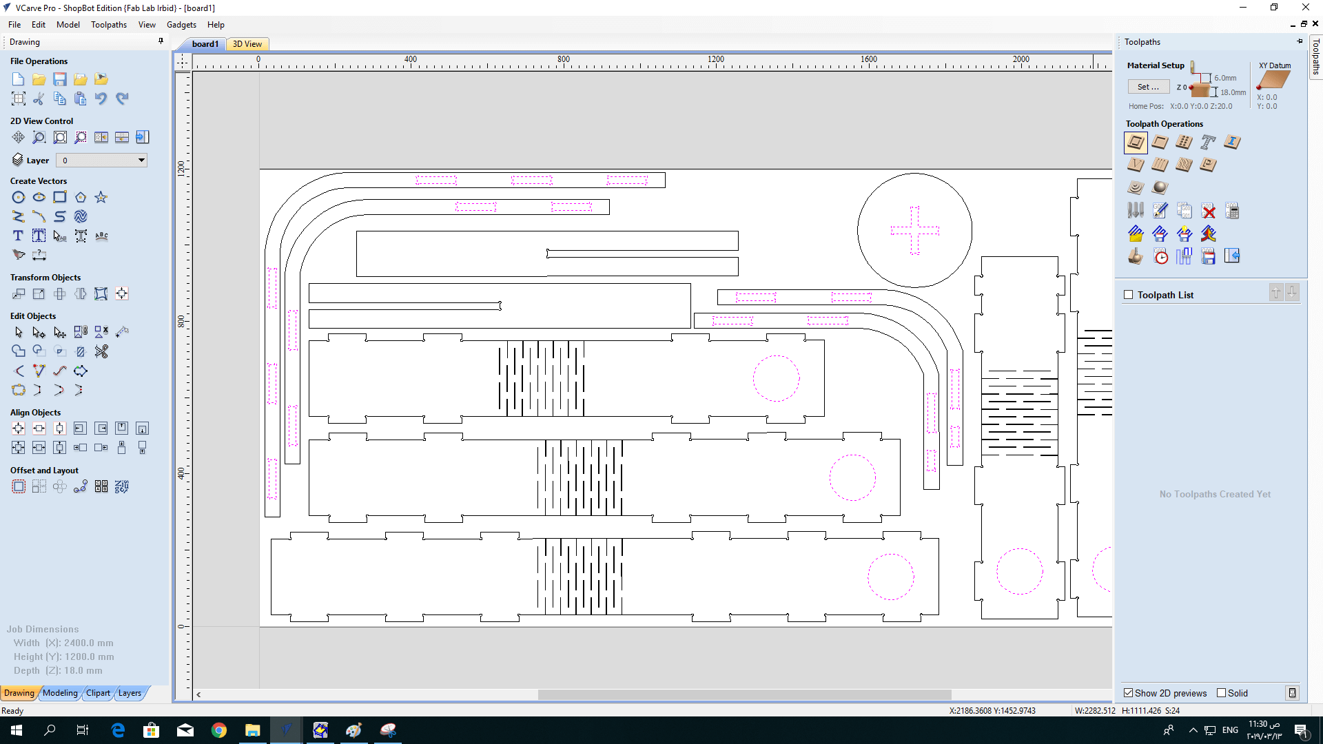
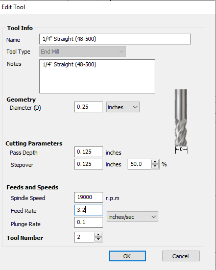
Next, I added the information of the cutting tool:
here, I had a problem, as the distance between the hinges frame line was smaller than the diameter of the cutting tool, and since I sat it to be cut from outside, it didn't show in the simulation and it just skipped it. To solve this, I drew new lines in the middle of the original ones, and then chose to cut them on the line.
After finishing with program, I saved the vCarve file, placed the wood board on the bed and fixed it using nails.
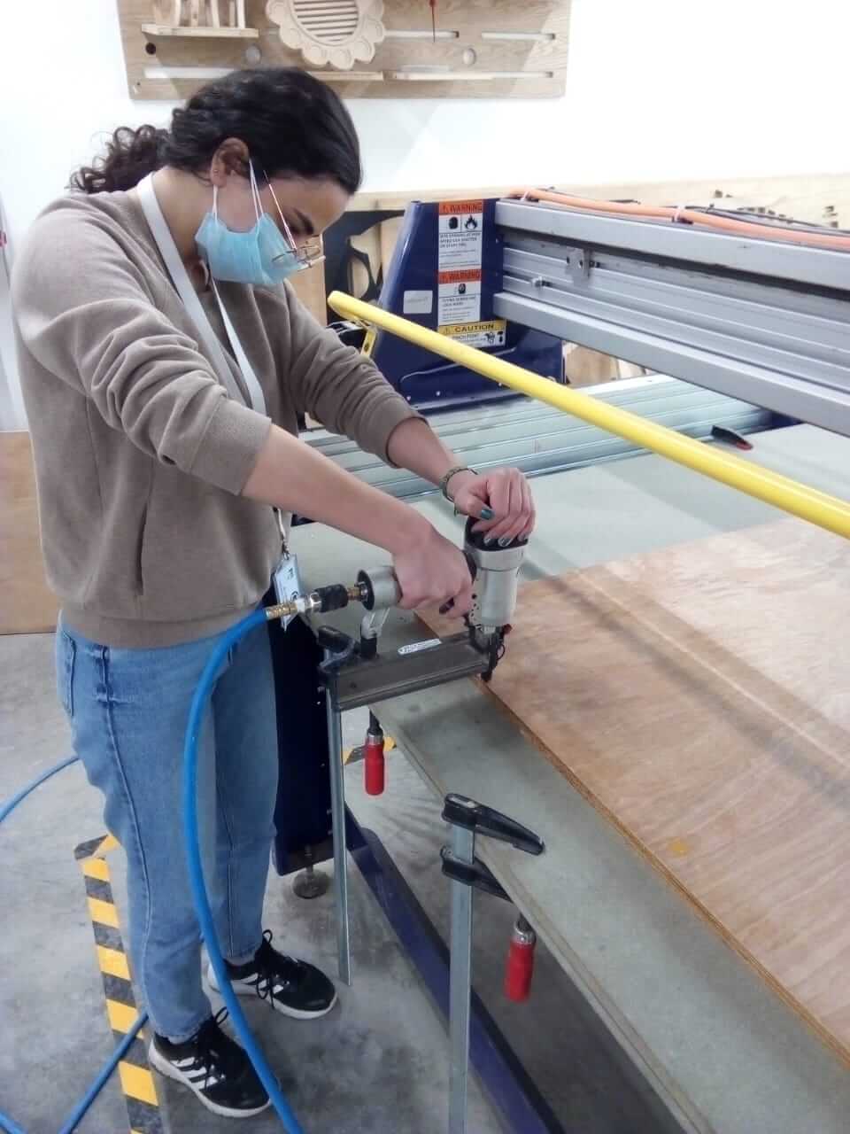
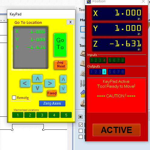
Now, I proceeded to set the XYZ axis. For the X and Y axis, it was straight forward, as I moved the spindle from the ShopBot panel on the computer. As for the Z axis, I placed the calibration plate beneath the cutting tool on the board, and the alligator clip on the cutting tool, and then from the computer, the head automatically calibrated the Z access by lowering down till it touched the plate.
I then ran the program. In the beginning, it went well, but after around 15 minutes, I stopped hearing the cutting noise from the machine that was when it started. I stopped the machine and checked and found the cutting tool to have broken, I changed it and proceeded with the cutting process.
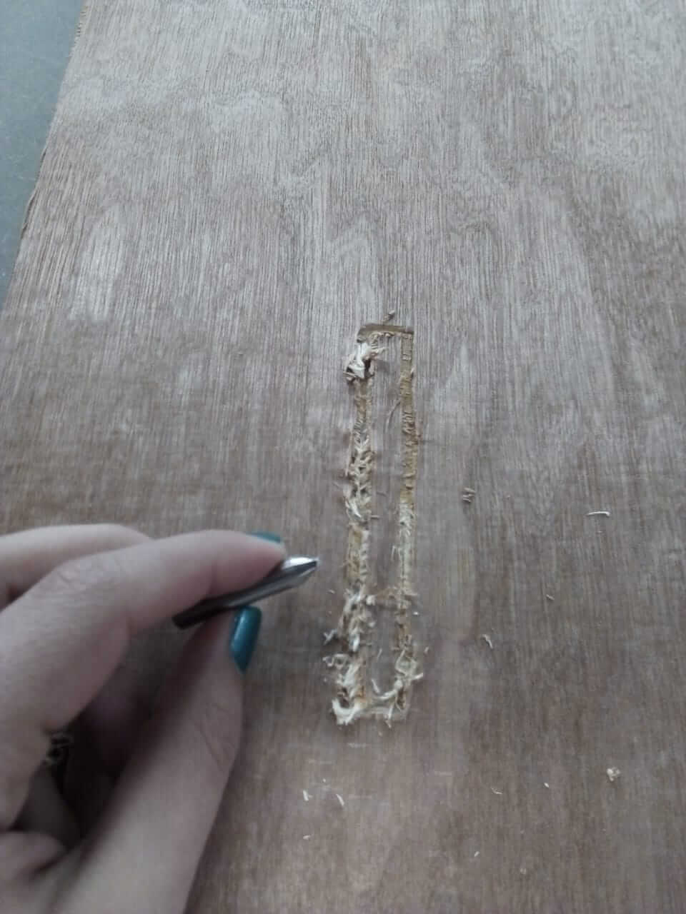
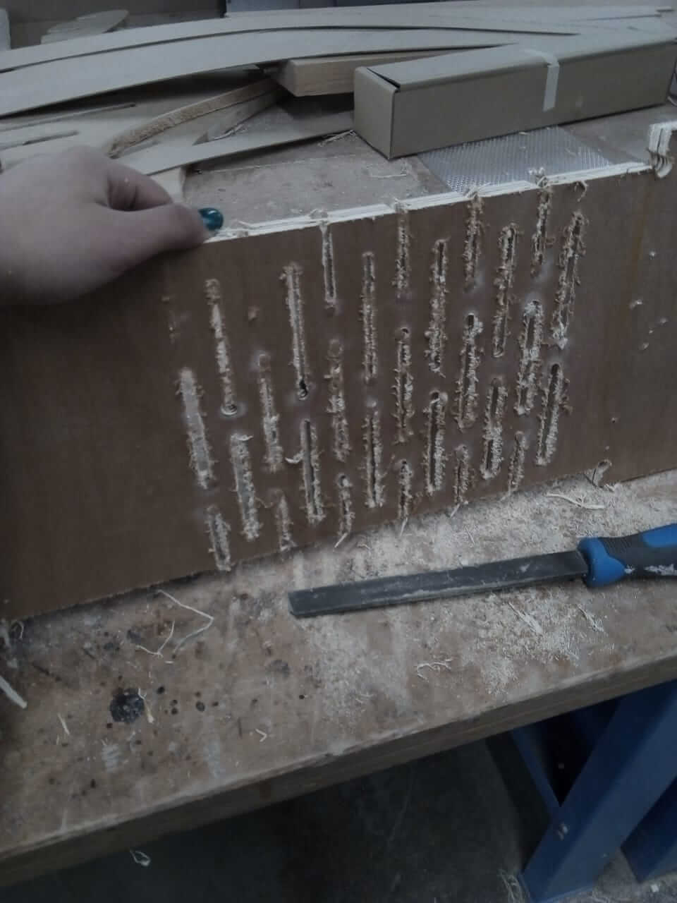
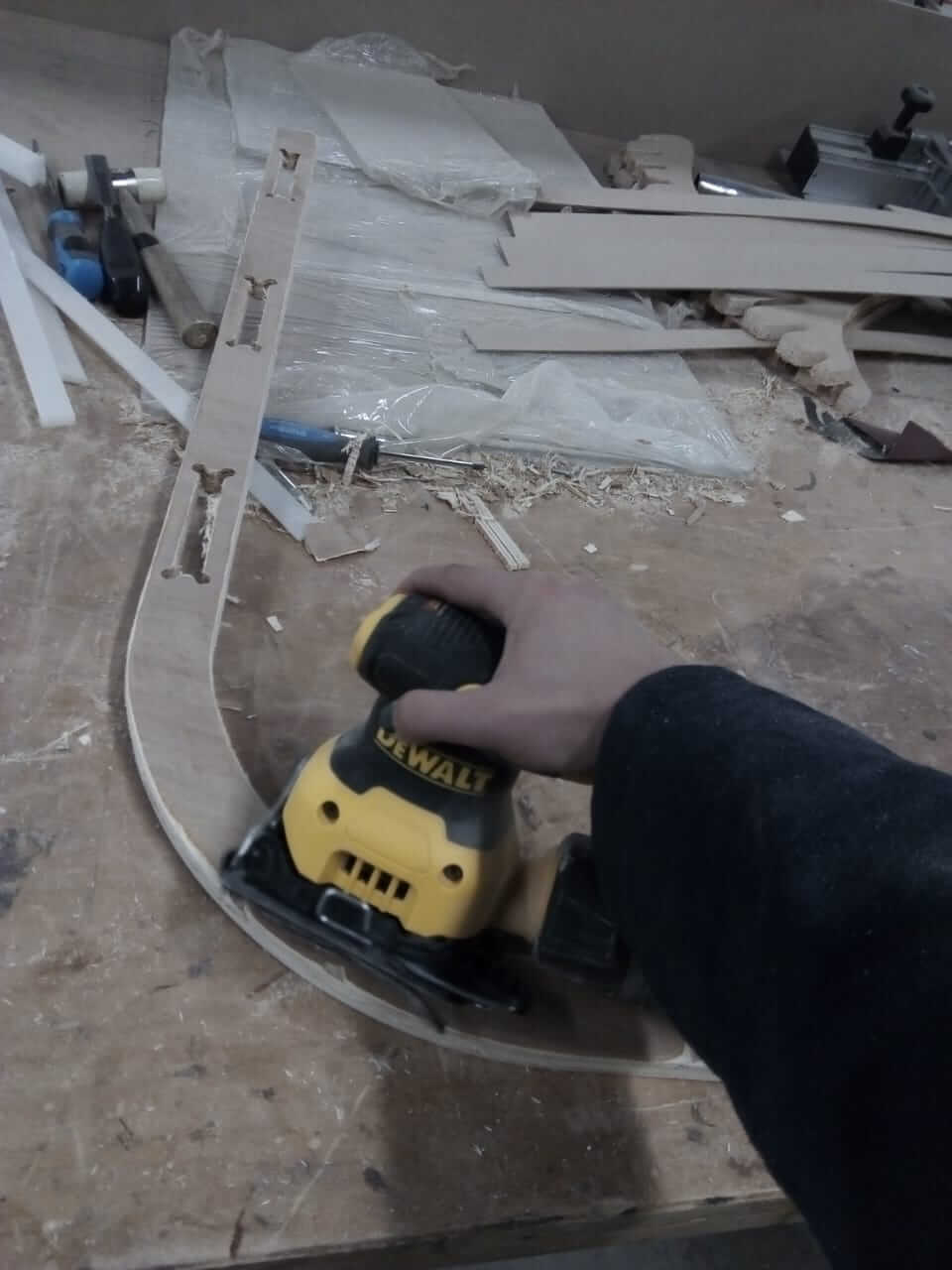
when the board finished, I removed it and checked it. I found that some holes weren't cut all the way through, which was probably because the board was concaved, but I completed the holes using a file, and then sanded the parts for a better finishing.
Here comes the fun parts :D I added the pieces together and assembled the body, and here you cane get a better understanding of the "thing" I was trying to describe:
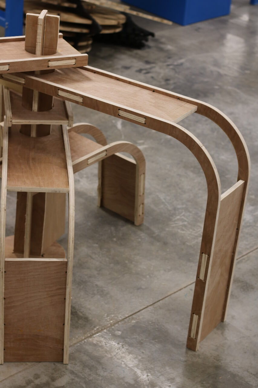
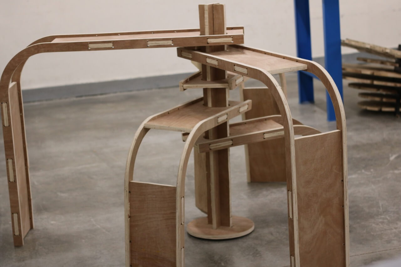
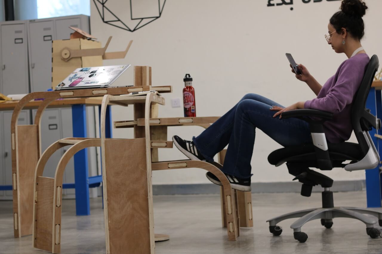
And here is an example of how it can be used. Of course, one can use it in any other way they would like, a table, chair, ladder...etc.