MECHANICAL DESIGN: FABLAB SZOIL
The assignment of the first machine building week:
Design a machine (mechanism + actuation + automation), including the end effector, build the passive parts and operate it manually.
MECHANICAL DESIGN
Initial Ideas
This week we learnt about mechanical design, including different vendors of mechanical parts/materials, some principles in mechanical design, different materials adopted in mechanical design, different elements of the mechanical design (adhesives, fasteners, pins, framing, drive, guide, couplers, bearings, rotary, lubricants, cables, liquids, conveyors, springs, and mechanism etc.)
And this week we only have group assignment, because it’s a part of the machine building task. However, we do need to specifically document individual partakes in the group assignment. Here are some requests of this week’s assignment: - design a machine that includes mechanism + actuation + automation
- build the mechanical parts and operate it manually
- document the group project and your individual contribution
There are only two students in Shenzhen, and neither of us has any engineering background. And to be honest, we are struggling with fulfilling weekly assignments and have been thinking about the machine making task since a few months back. However, we still do not have a confirmed plan as to what machine to make.
We have been discussing about the following possible options:
- a fortune telling machine
- a vacuum former
- a CNC
- a vinyl cutter
- a spirograph machine
The fortune telling machine was the initial idea. I was thinking of making a random generator of quotes, when the user press the button, the thermal printer will print out a quote that will lighten up the user’s day.
As to the other three ideas, they should be something useful in the labs. However, after some doing some researches, it seemed the idea of making either a vacuum former, a CNC, or a vinyl cutter to be too ambitious for us for now. So we need to get other ideas!
And it suddenly occurred to us that we (like many others) used to love plying with spirograph when we were little kids. And the idea of making a spirograph machine brings back the beautiful memories from our childhood. So the decision was made: build a spirograph machine!
Here's our insprition video below:
Researches
We did some researched and found the following links most helpful!
(1) This tutorial from Fab Lab RUC Denmark has very detailed information and even the design files as well as code for making a spirograph. In order to learn about the mechanics behind it, we downloaded the file and make the same one. However, we did not manage to get it working as shown in the tutorial. The main reason lies in the Guino app, which was used to control the motors. Since the MacBook we are using is version 10.14.3, and the Guino app is not updated to the latest version yet. So the app interface was unusable.

What’s more, after consulting Violet’s colleague Nicho, he pointed out the motor that we used was not the right one. We needed 360degree motors. So we ordered two from Taobao.
While waiting for the motors to arrive. We kept digging for other resources about making a spirograph! We ran into this Youtube video which is a very good one for me to learn from.
So we decided to make a spirograph similar to this one. And then we will add controllers + motors etc. to make it work automatically.
Design
First of all, we need to design the gears. We used Inkscape to design. Terminal => Inkscape => press “enter” to enter the interface of Inkscape on Violet’s Mac. To design gears, Inkscape has a very good extension, Thank you!!! It made it much easier for me to design the gears.
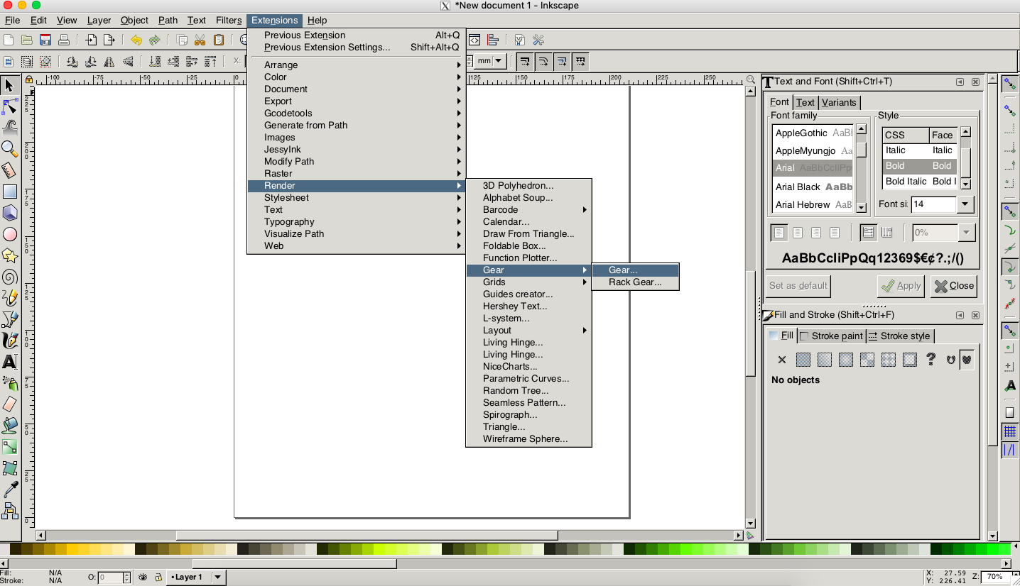
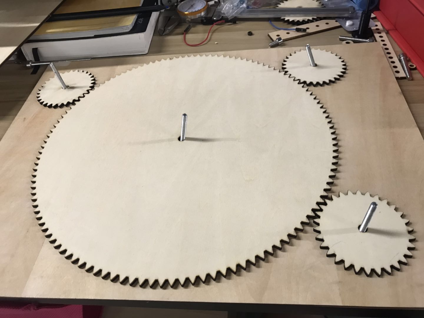
However, we did have some detours in this process. With the first version, the holes in the middle were too large, and when we put the screws in, the whole system was too loose which was not able to be kept balanced.

So we re-calculated the gears (diameter: 3.5mm), and since the first version gears were too large, we decided to make a smaller version. And here it is!
Even though the holes are perfectly matched, the three gears (the ones surrounding the central one) were too tiny and there was no space for me to put pillars on for holding pens.
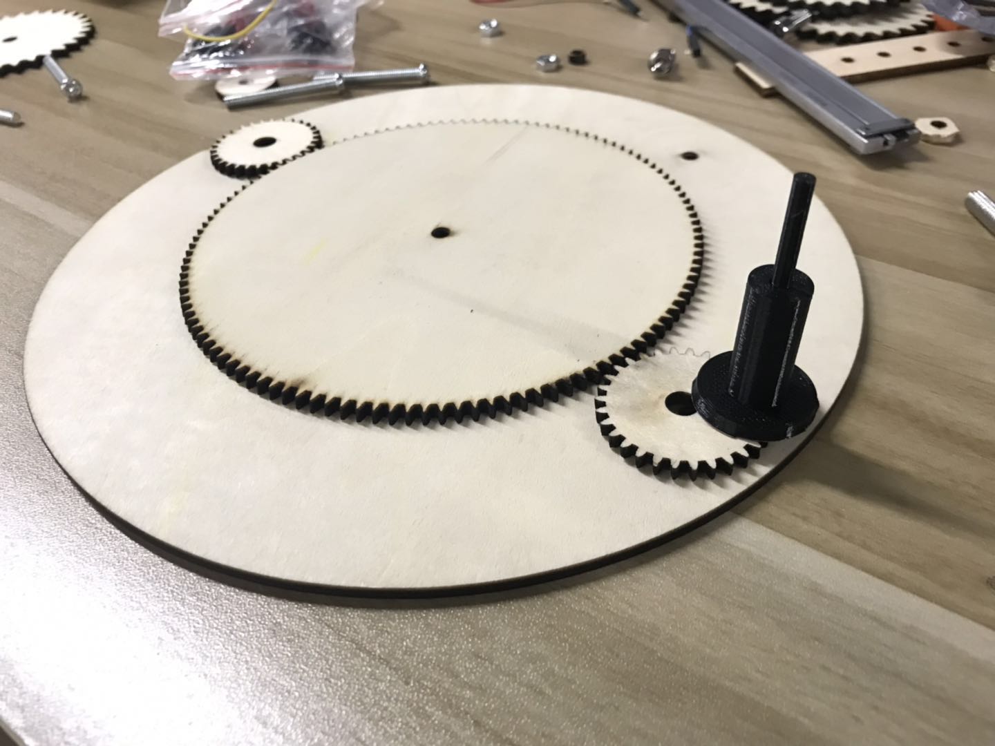
So we made another attempt.
This time, we re-watched the video several times and listed all the parts needed for this project. We decided to mainly use laser cutting and 3 printing to make the above parts (except the rubber rings which we already placed the order on Taobao.)
parts to be laser-cut:
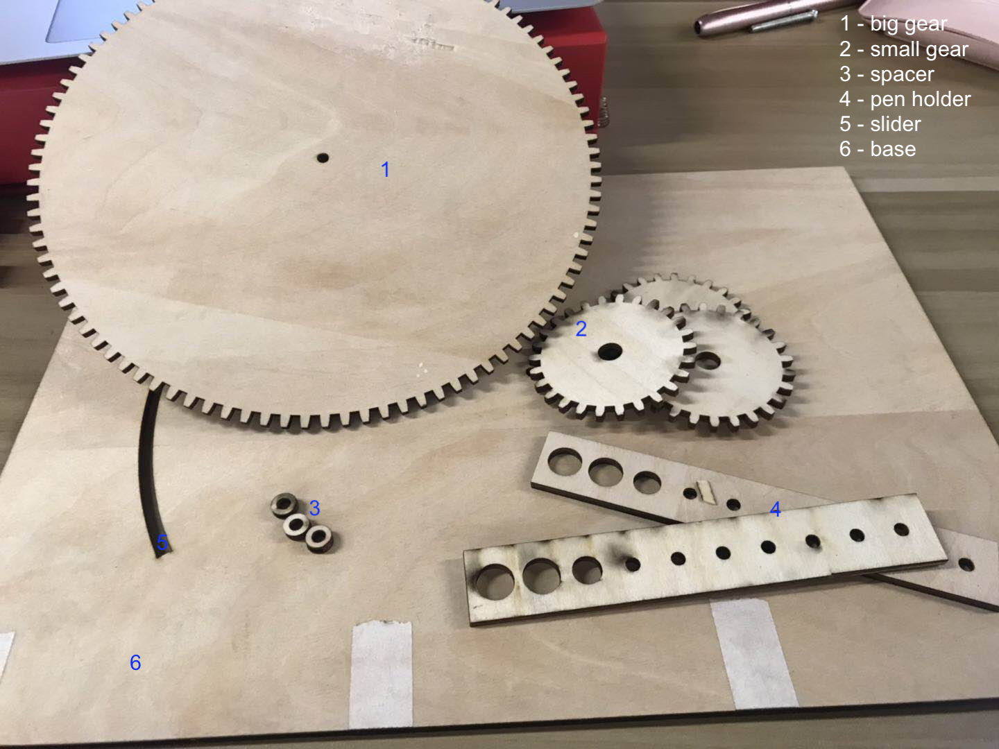
- large gear * 1 (This is the center part, for placing papers)
- small gear * 3 (These three gears will be: 2 holding the pens, one connected with the motor)
- spacer * 3 (to make sure the gears can move smoothly while doesn’t affect the screws and bolts while moving)
- chaise * 1 (supports the whole system while defines some crucial parts)
- hands to hold the pen (as the axis of the drawing)
parts to be 3D printed:
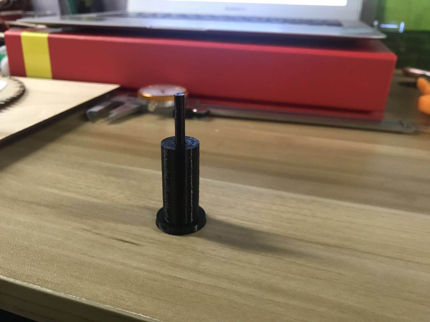
- central peg * (which will make sure the central part fixed in the center and yet it can be spinning)
- side peg * 4 (work as the legs of the machine)
- pen holder * 2 (they act as pillars to hold the pens)
parts to be purchased
- rubber ring * several (to secure the parts)
And then we made the 3rd design!
(1) We made designs for the big central gear. (see the respective parameters in the following picture)
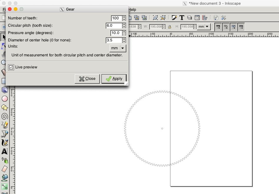
(2) We made designs for the 3 small gears. (with the following parameters)
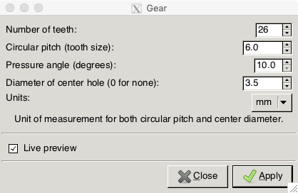
(3) Design two bars for holding the pens (with holes on the rectangle bars, small holes as the positions, which should be the same diameter as the pillar points; and big holes the same diameter as the pens. Here we choose one hole for normal pencil, two holes for color pens.)
(4) To choose the positions for holes on the base, we grouped the gears and copied it to the right as a whole. And then we added a ring. It turns out the circles of the rings were made of different parts, so I deleted some and left the last part as the slider for some more options in drawing.

(5) We deleted the gears on the right part (the base). And then we readjusted the locations of the gears, the pen holders etc., to make good use of the material space as well as get some spare small gears.
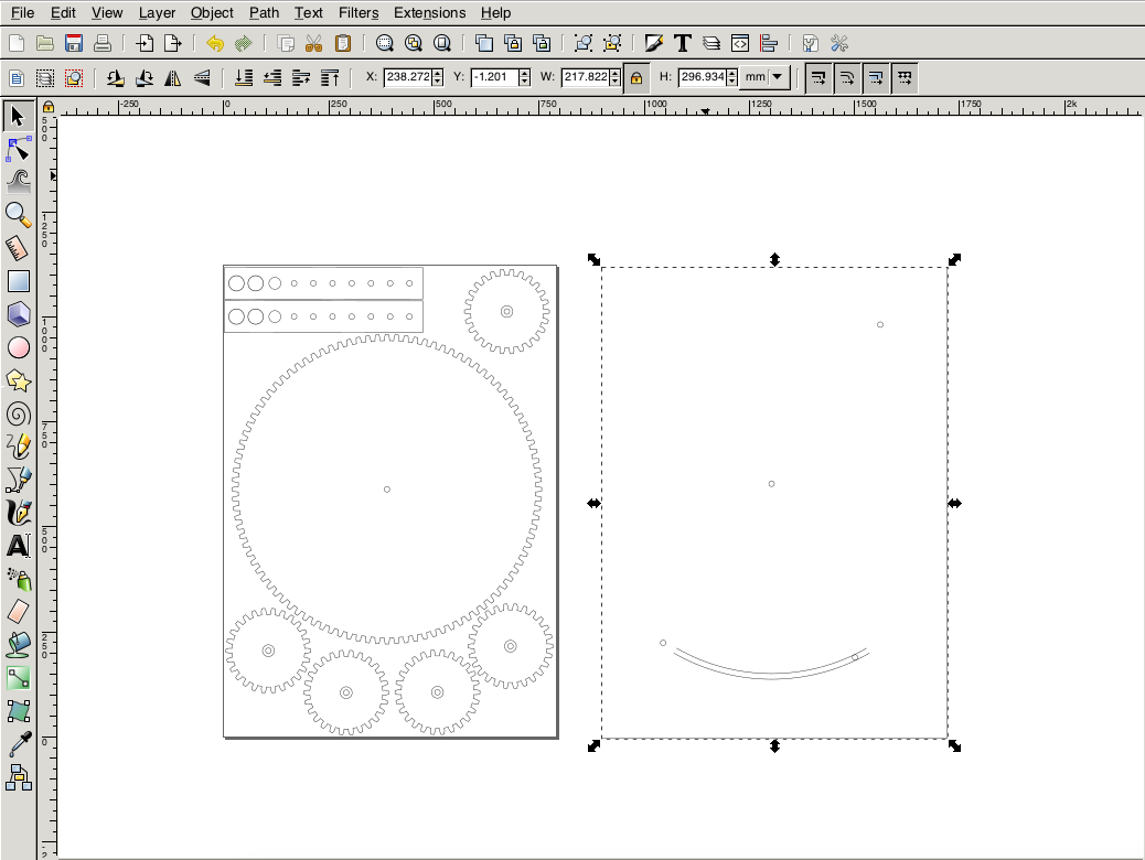
Have you noticed that in the left part, within the small gears, there are two circles? The small circle is the same diameter as the screw, for holding the parts together. Combing the small and the middle circle, I got a tiny ring, which will act as the spacer for the small rings!
With all the designs ready, we exported it as .dxf files.
Now it’s time for laser cutting!
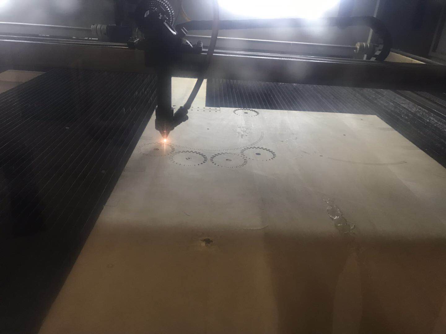
It turned out we forgot to add two small lines in the slider part. As a result, it only cut two curves and it remained on the board. Luckily it’s not a wide one, we used a knife to cut it out very easily.
Here you see the laser-cut parts are ready!
And here are the 3D design & 3D printing process.
Since our machines at x.factory are usually busier during weekends, when we finished designing the 2D files, the laser-cutter was still occupied. So we went on designing the 3D parts. We used Fusion360 to make the central pegs and the pen holders.
Both are very simple designs with sketching circles and then extrude them into the desired dimension. And then we exported them as .stl files, which will be converted into gCode files for printing.
We also made some detours in the process of 3D printing. Mostly because we miscaculated the heights and diameters. It was trivial yet time consuming. Lesson learnt: to be patient and make sure the parameters are set correctly before actually making the physical parts.
Here are the 3D renderings.
Now we have the pen holders ready!
And we assembled all the mechanical parts to try & see the results! However, it seems we miscalculated the holes for the pens, so we redesigned the hands.
And we also used double-sided tape as the “legs” of the system to make it balanced.
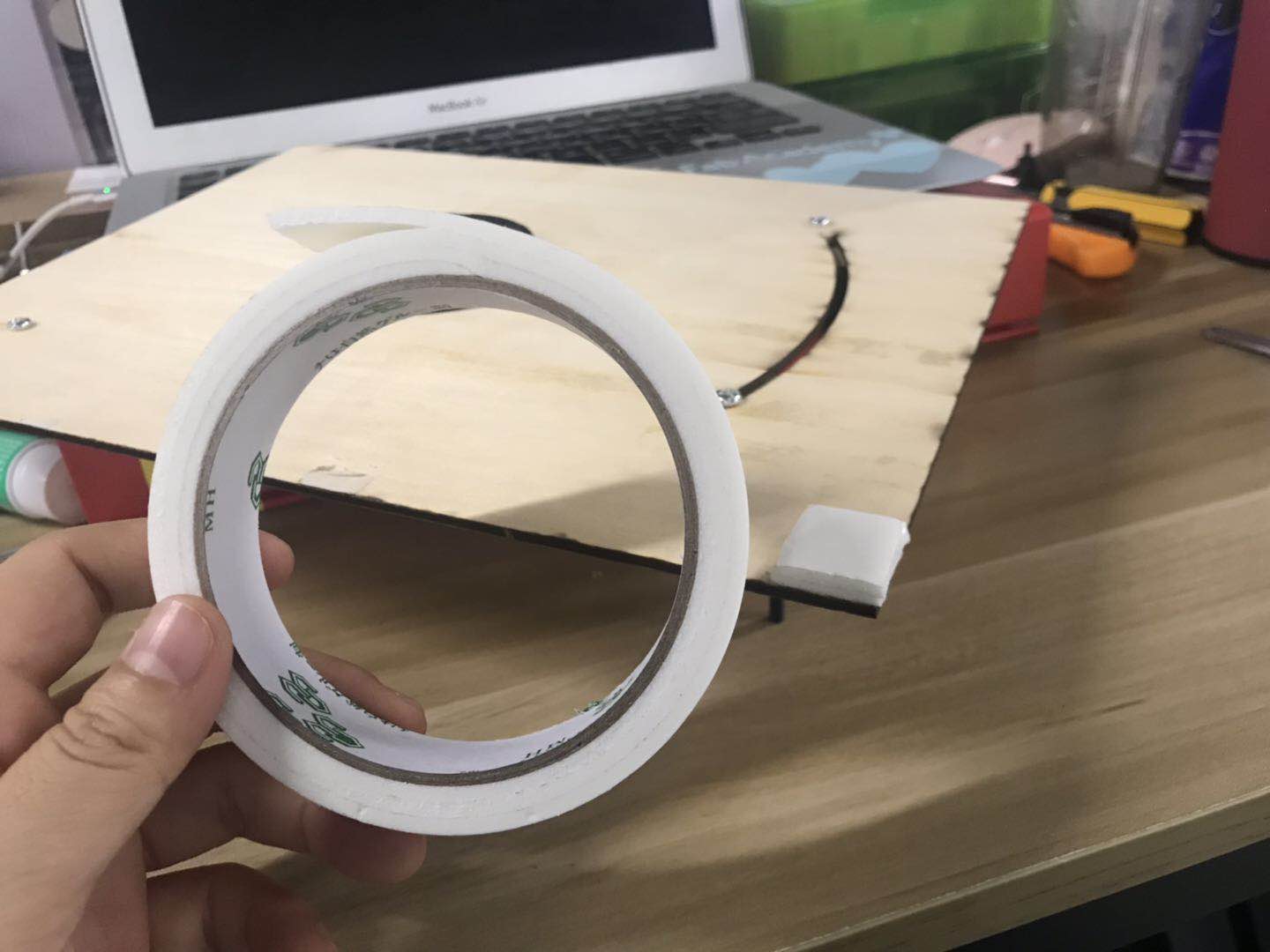
And then we collected all the deserted A4 papers in our office, used laser-cutter to cut them into round shape for drawing. Since the paper is very light, we placed the plywood board from the last cut on the papers to keep the them in the right location.
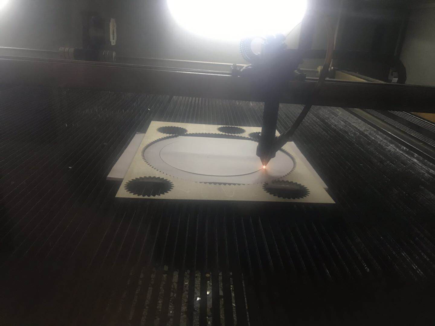
Now it’s time for testing!!
It worked!
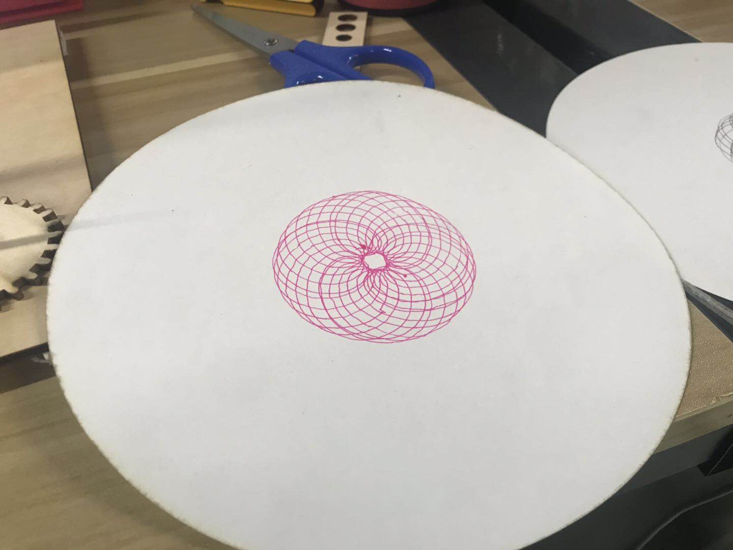
It’s not very smoothly, and yet it worked! Next step: make it automatically drawing!
Files
Here are the files of mechanical design:
Mechanical parts in 2D