Back To Top
Week 06 - Electronics Design
What is a multimeter?
A multimeter is a device that allows us to measure voltage, resistance, and current (at least). It can include more measurement functions and it is commonly used in electronics to debug (to understand where the circuit is not working for example).
Measuring a microcontroller with a multimeter
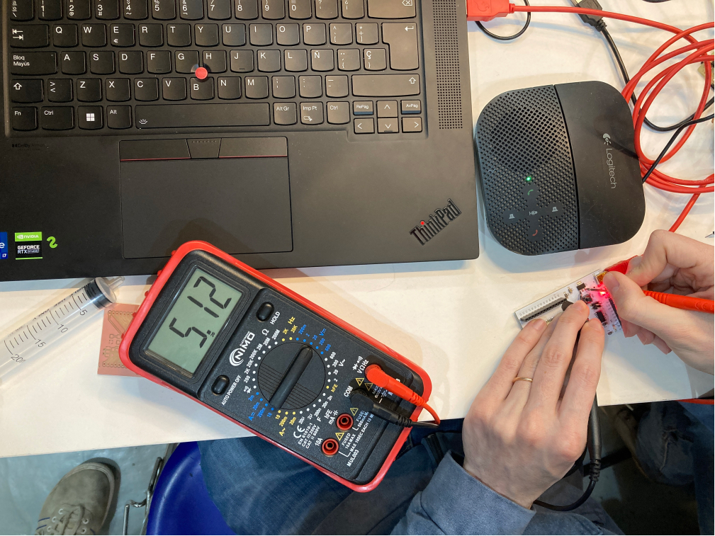
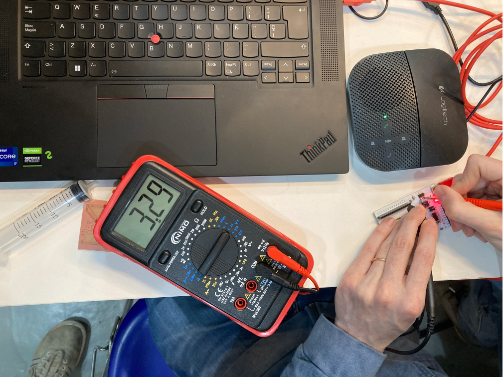
We used the microcontroller to measure the voltage on our FabLab Barcelona board - Barduino. It is very easy to understand the multimeter, we simply need to define how much voltage we want to measure (up to a specific one) and then use the connectors (positive and negative) to check how much voltage is passing from one component to the other. This allows us to understand if the circuit is actually working! For example in this image above we are measuring 5v current (the voltage feed from the laptop into our DC board).
Measuring the current in the led...@manu @ana @aurel @marc
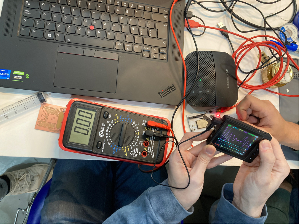
Using the osciloscope...@manu @ana @aurel @marc
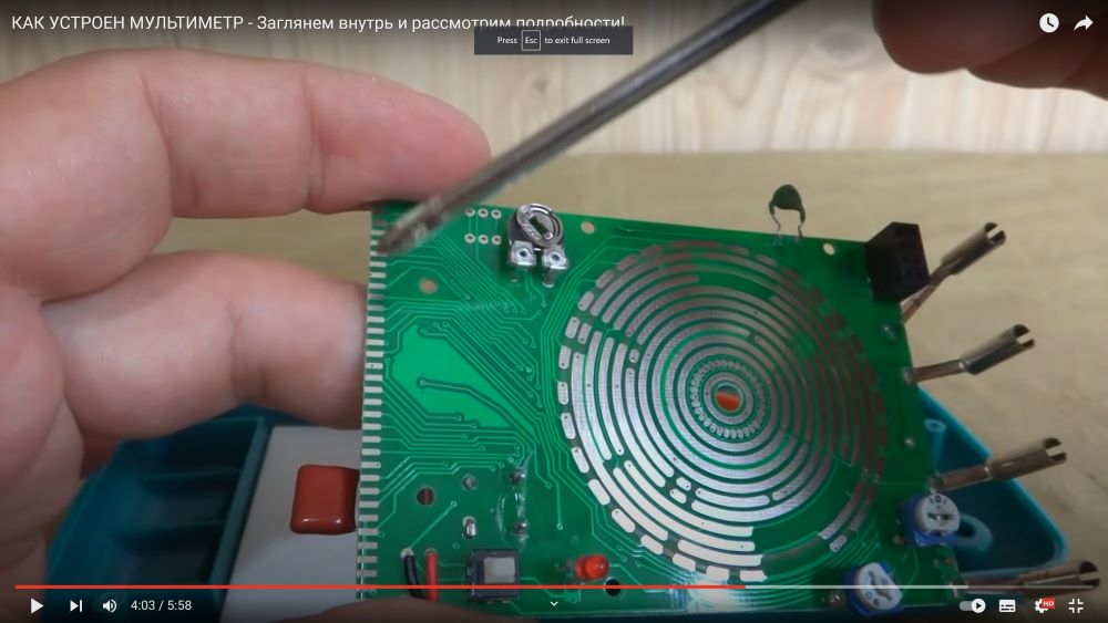
Multimeter strucruere
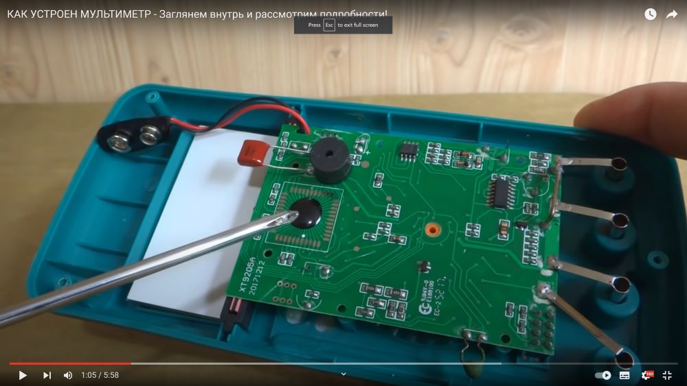
Teardrop-shaped chip chip, applied directly to the printed circuit board.
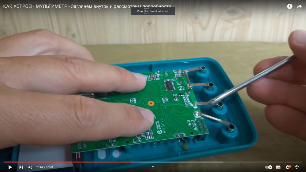
Conductors are connected to the sockets, they must have very low resistance, usually they are coated with silver or a well-conducting non-oxidizing metal.
A large metal shunt bracket for passing very high current (the voltage drop at its ends is recorded by the chip and displayed).
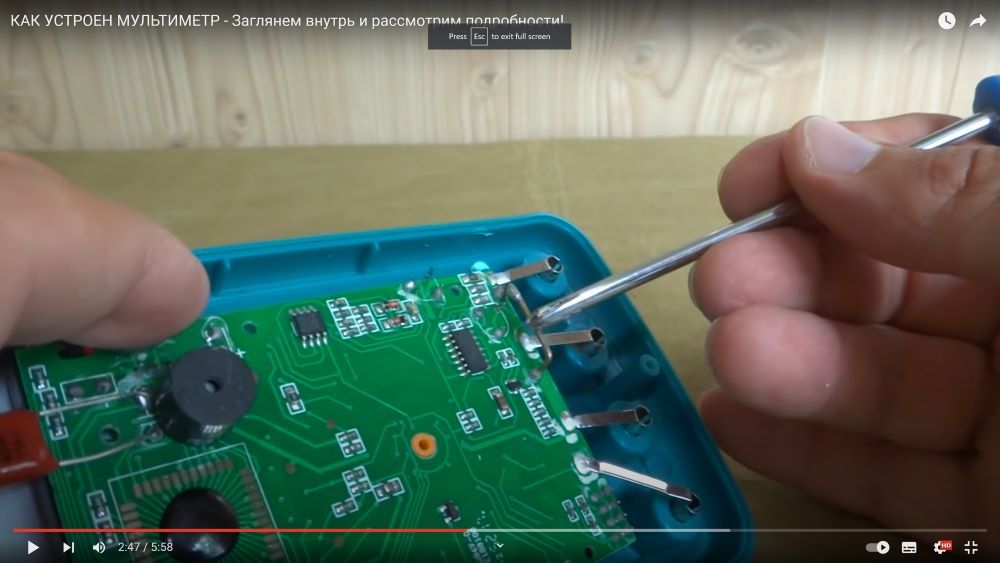
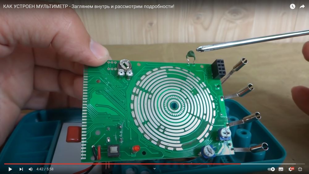
The source of the sound signal when ringing is a finder, PC speaker, boozer (outputs a signal if the diode is in good condition or very low resistance, in the ringing mode of short circuits, semiconductor diodes, transistors, etc.
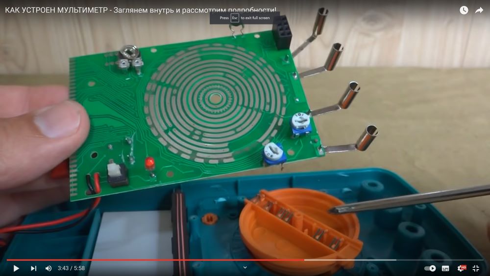
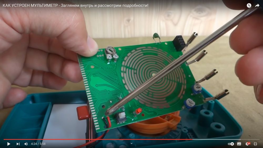
Contact krupp for multi-function rotary switch
Leads to the contacts of the liquid crystal display.
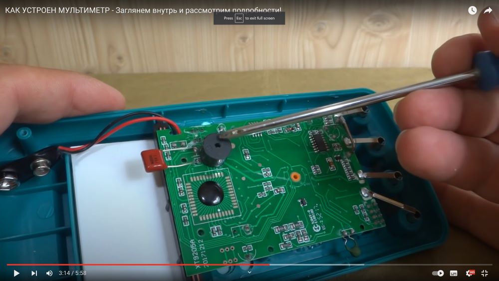
The off/off button disconnects the adjacent two wires from the battery, as a result, the power is removed from the entire board, and the present indicator light signals when the semiconductors ring that the conductor is located in the right direction.
Stabilizer - thermistor with PTCS (Thermoresistors with PTCS are semiconductor thermosensitive resistors, which have an abrupt increase in resistance when the rising temperature reaches a certain value) for resistance, depending on the heating of the device, the operation of the microcircuit and microcontroller is compensated.
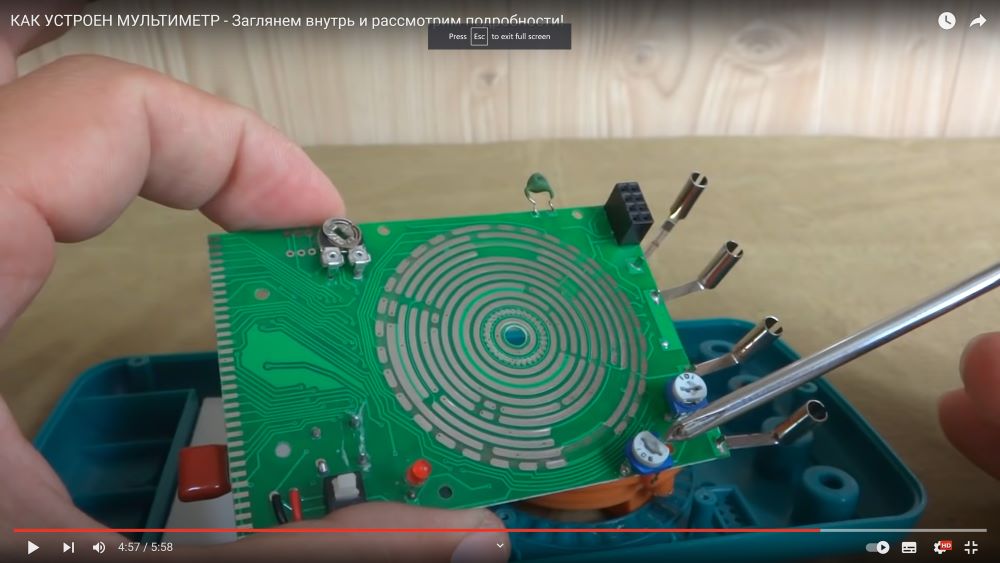
2 tuning resistors, connected as a variable resistance, with only 2 feet in the circuit where currents and voltages are measured, serve to ensure that the spread between the parameters of small elements during installation does not affect the accuracy of the device. For precise adjustment, a reference resistance is set, a reference voltage is applied and with the help of these resistors, the device is manually adjusted to the standard.