Back To Top
Week 08 - Electronics Production
File preparation
For the preparation of the file, we start from the file that was exported in KiCad in svg format of our circuit. With this file, we are going to work in a CAD program (Inkscape was used) and correctly separate the zones that we want to machine in a different way. In this case, we have 3 differentiable zones:
- Traces
- Holes
- Outline
It is important to be clear that the area to be machined will be the black one. Therefore, in Inkscape, we will work with different layers and we will export what we are interested in each one of them.
First, we are going to include a black background. Our "Traces" file will consist of a layer with a white background and another layer with the traces (F_Cu) in white. The "Holes" file will be formed only by the holes in black, this time with a white background. Finally, the "Outline" file must remove the rounded corners and set only the rectangle in black.
The main care to be taken in the preparation of the files, besides having to be independent files since they will use different tools and parameters, is to keep the same size and origin to the 3 files. To do this, in Inkscape, you have to preset the size in "export", using the largest size (that of the outline) as the preset size. To do this, we preselect this layer, we give it to custom settings, and already by default are used for all (unless modified).
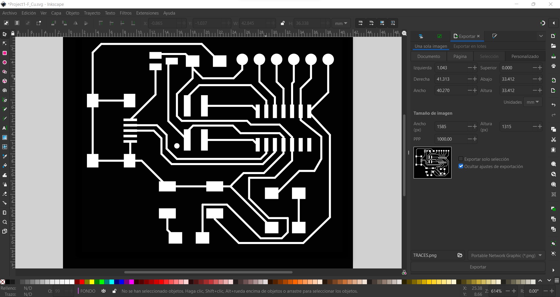
Thus, we will have 3 files in png format with the same size and resolution.
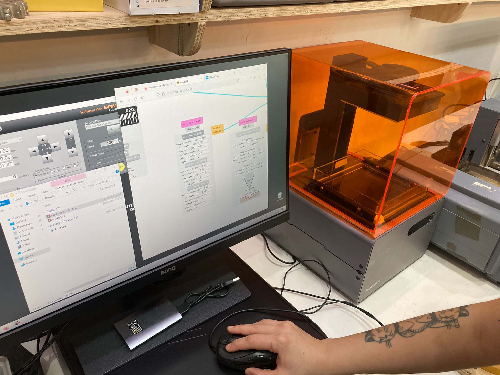
Machine preparation
From each of the png files, we can go to https://modsproject.org/ to generate the machine code. Here, we can click on any area of the screen to include a program. Right click on programs --> open program --> Roland - SMR20 mill - PCB.
We can insert any SVG or PNG file. In this case, we inserted one of the png images. For this we followed the same order mentioned above, first Traces, then Holes, and finally Outline, to avoid movement or possible vibrations when machining the outer contour. Here we are shown some default tools, which in turn, have some predefined parameters. The main parameters to be taken into account are shown in the following table. Caution, on the recommendation of our instructors, some of the default parameters have been modified to obtain better results.
| Pattern | Tool | Speed [mm/s] | Max depth [mm] | Offset number |
|---|---|---|---|---|
| Traces | 1/64 | 3 | 0.101 | 4 |
| Holes | 1/32 | 2 | 1.750 | 1 |
| Outline | 1/32 | 1.5 | 1.750 | 1 |
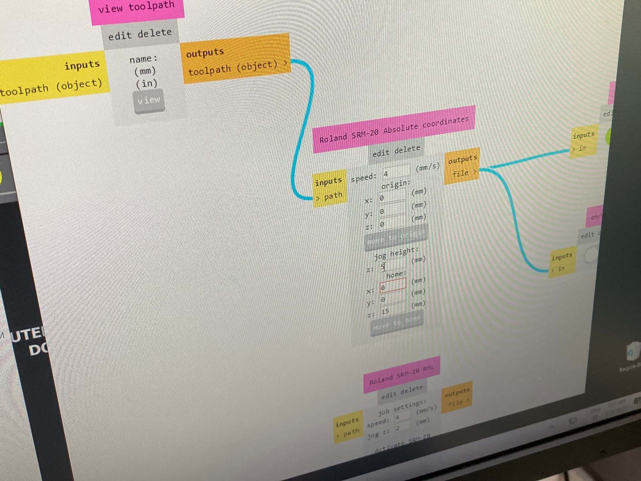
The machining direction was climb for all cases. Also be careful with the origin (recommended to put 0 in X Y, but put a higher number in Z, like 60.5 that comes by default), and with the jog height where it is recommended to put a height of at least 2 mm (we put 5 mm).
Preparing the file to the machine
@manu or @marc ...
.jpeg)
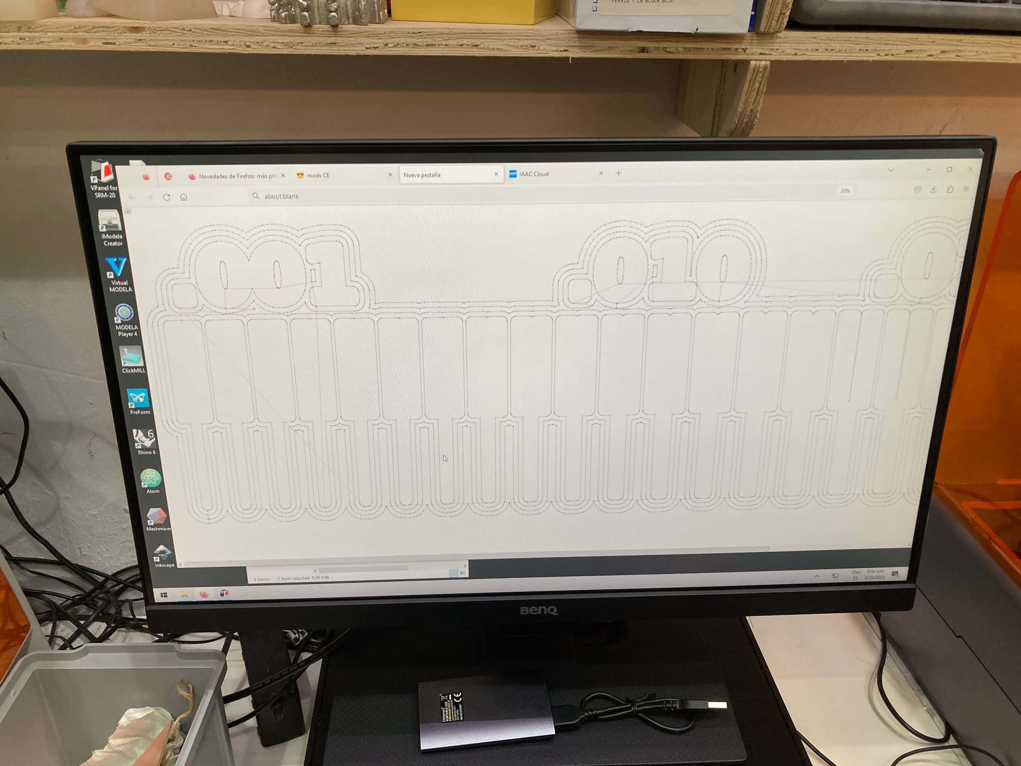
To make the board, you need to create a code file based on the imported PNG. We import a standard test to check if the current settings are suitable for the required track thickness. We press the mill traces button by pre-setting the settings or using the standard.
.jpeg)
The most important settings are speed, maximum depth, number of offset passes (to avoid short circuits due to copper pile when cutting or solder sticking to unwanted areas when soldering).
It is also important to set the height to which the cutter rises when moving above the board (5 mm is enough), if this is not done, the cutter will move in the cutting plane, destroying the connections being built.
.jpeg)
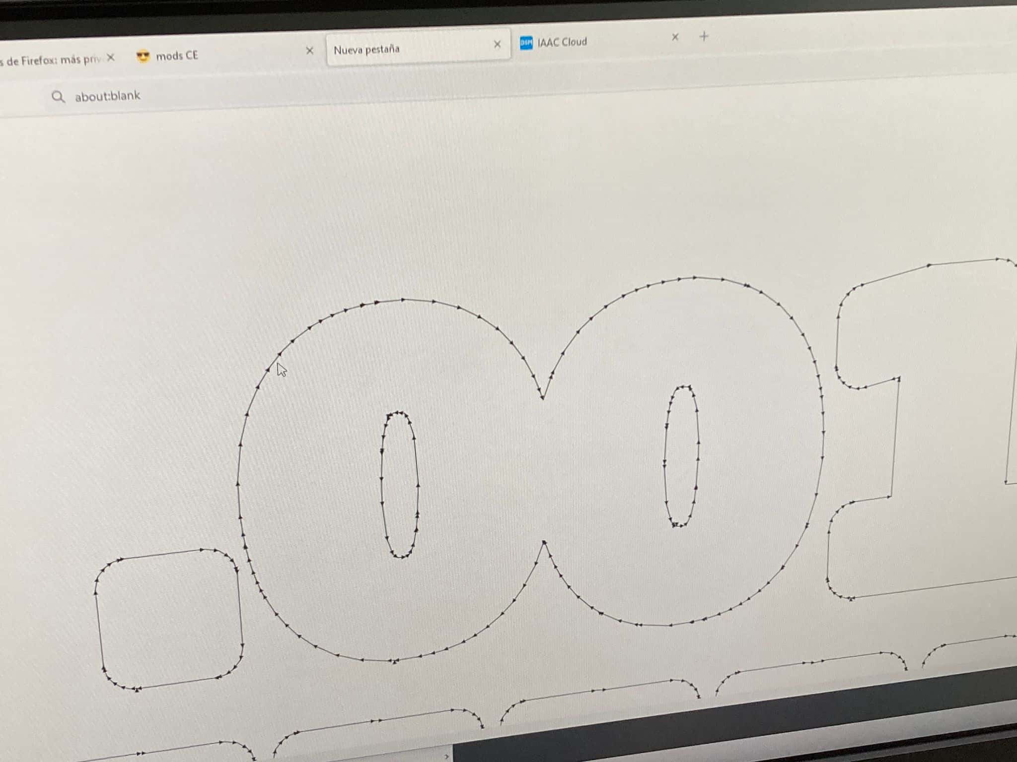
We switch the save file button to on, after which we press calculate, we check the resulting trajectory, so we can estimate where the cutter cannot go and change the offset settings. Add the resulting file to the output in the software for Roland and cut it out.
Machining
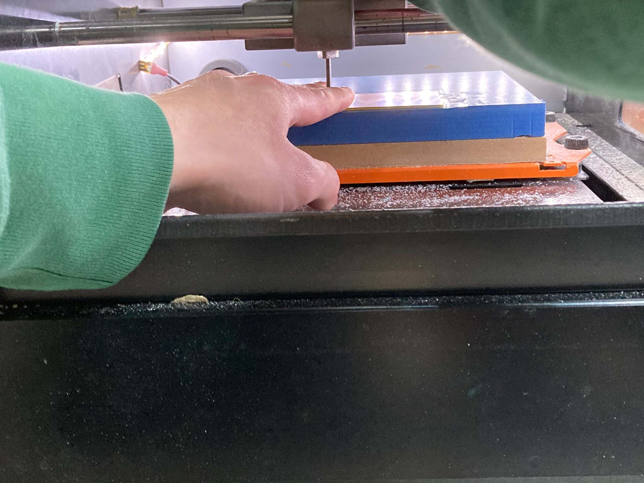
Once we have the machining files, we can start with the machine. The first thing to do is to place the tool to be used (for each case) and make sure that the plate to be machined is well fastened to the base. We used a 1/64 (0,4mm) endmill for the traces and a 1/32 (0,8mm) endmill for the outline.
Then to attach the PCB to the board we use double-sided tape, since the stresses are not so high as to require a more robust mechanical clamping system.
.jpeg)
.jpeg)
Then, we go manually from the VPanel for SRM-20 program to the lower left corner of the plate to make 0 in XY. . To set it up we simple click the "x,y" set origin button.
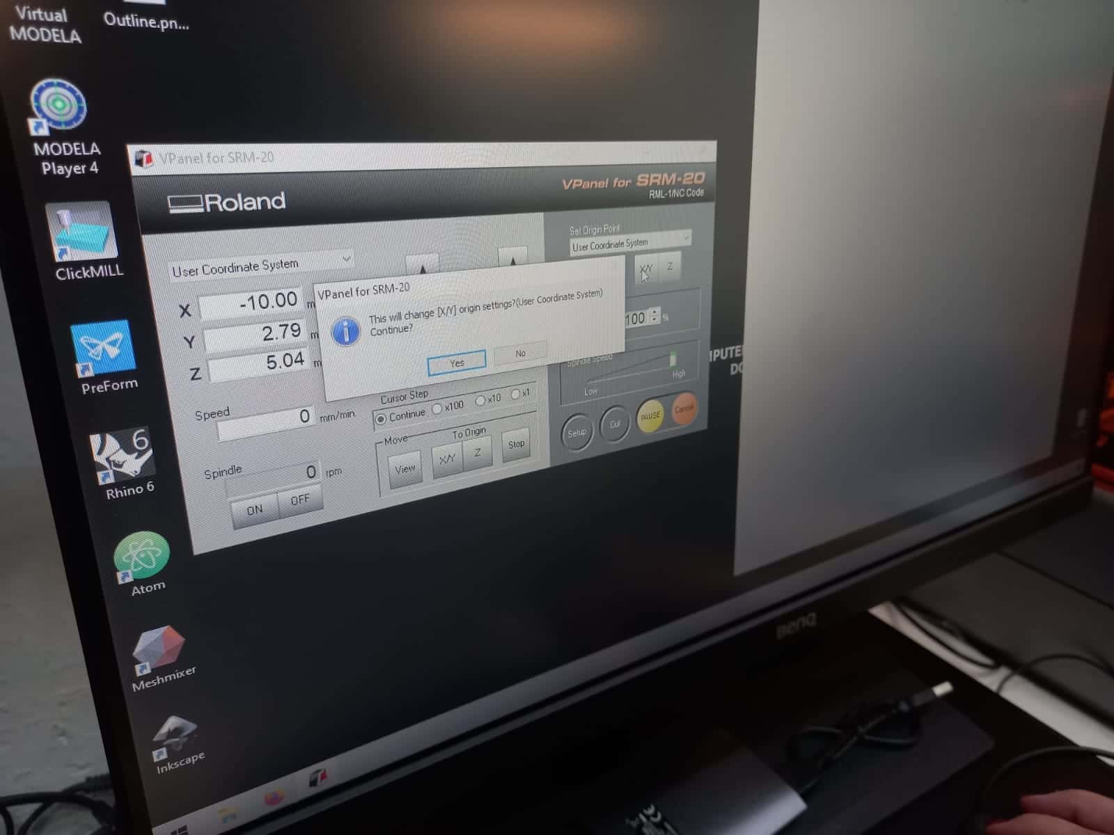
To make 0 in Z, it is necessary to start the spindle and lower the tool little by little (hundredth of mm by hundredth of mm) until it almost contacts the plate, then we go with our hands to unscrew it and drop it gently until it touches the PBC - this is because the endmill is quite fragile and can be broken very easily.
The results
@manu or @marc...
.jpeg)
.jpeg)
.jpeg)
.jpeg)
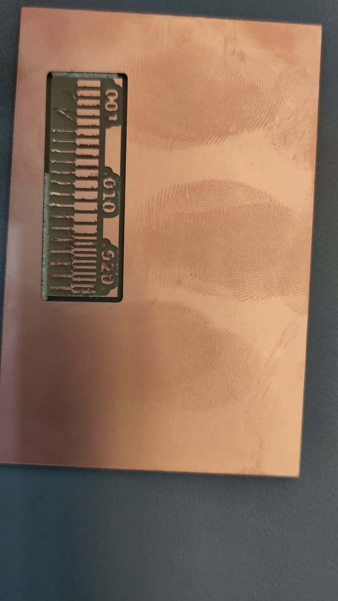
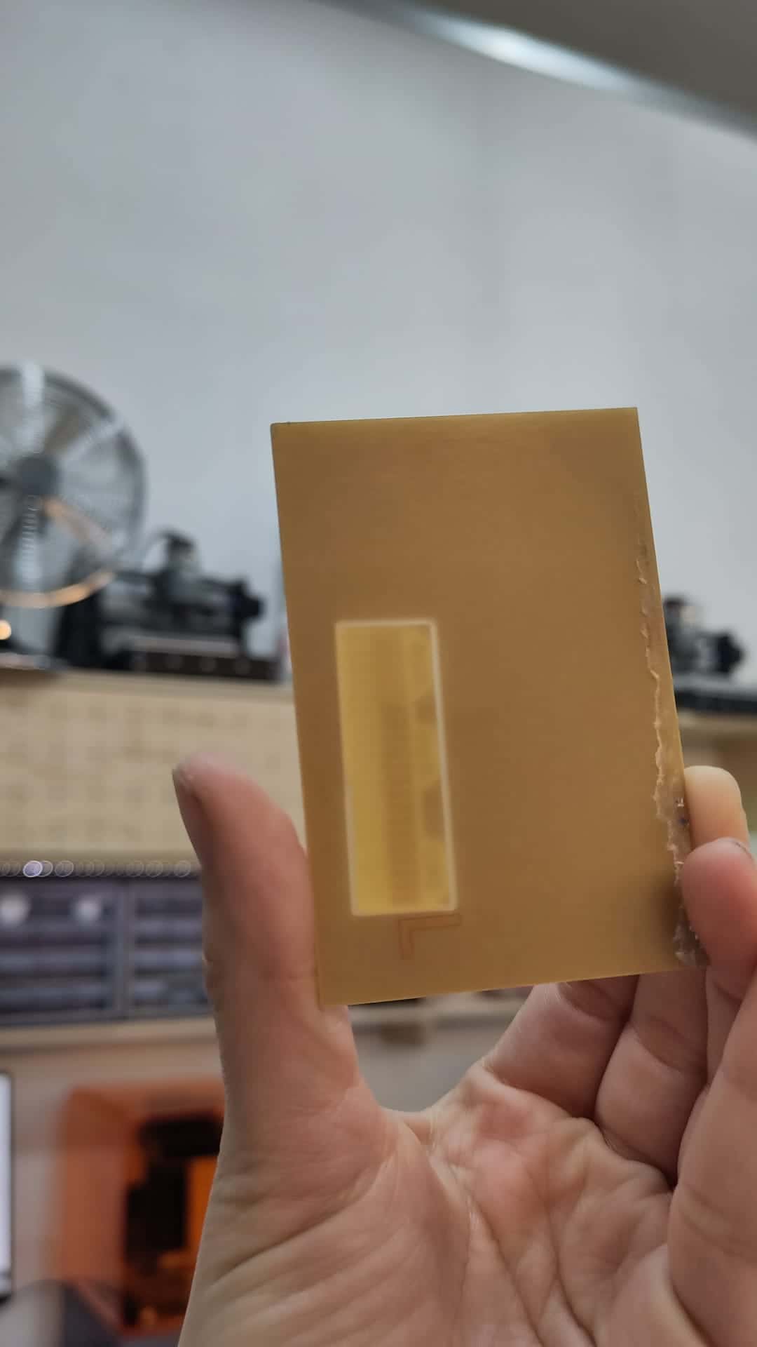
The cleanest cut was obtained for track thicknesses between 0.010 and 0.020 inches, the copper layer does not come off as at 0.010, nor does it nip as much as at 0.020 (although lint is a minor problem, it is easy to remove it by holding it perpendicularly along the surface, for example, the blade of a clerical knife), considering that in order to withstand the current, the tracks should not be thinner than 0.35 mm (for 5V, better than 0.8 mm), the test results are satisfactory. Also, the board was not completely cut along the perimeter of the pipe, which can be either an evidence of uneven positioning or an insufficiently accurately set cutting depth.