Back To Top
Week 09 - Output devices
Measuring output devices
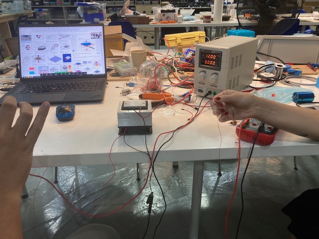
For this week's assignment, we measured the consumption of a few output devices. An output device is any device we can be using as an output of data. We measured DC motors, a LED, and the ESP32 using a variable power supply and a multimeter. To measure the consumption we checked the amperes that were being consumed since they can vary depending on what the output device request is for "feeding" themselves.
Measuring the consumption of DC motors
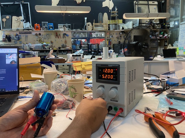
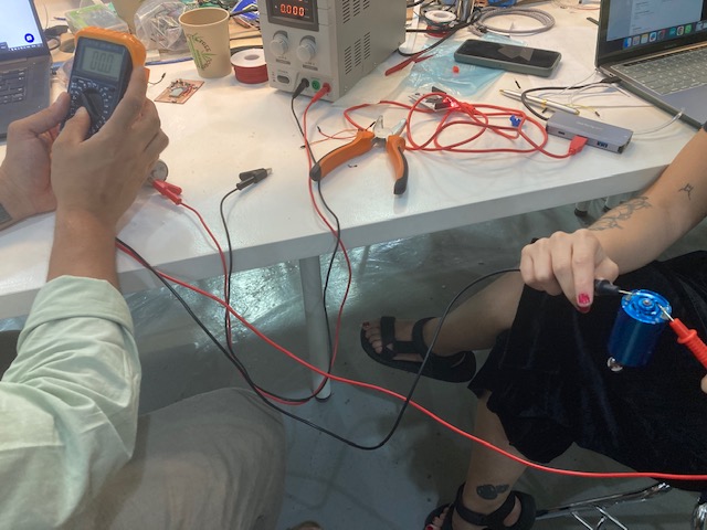
To measure the power consumption of a DC motor, we used a multimeter in current measurement mode that was capable of handling the current required by the motor.
We first selected the range in which we expected the motor to draw. The instructors' recommendation if you don't know the range is to choose the highest and work your way down.
Then we disconnect one of the motor leads and connect the multimeter in series with the motor. Connect the motor lead to the positive terminal of the multimeter and the other terminal of the multimeter to the lead originally connected to the motor.
Finally start the engine and observe the reading on the multimeter. Although the engine had to be allowed to run for a while to get a stable and accurate reading. It is important to note that DC motors may have a higher initial draw when starting due to the starting current.
To measure the consumption of output devices, such as motors and LEDs, there are a few factors to consider. For motors, the thickness of the cable used affects its resistance. Thicker cables have lower resistance and can handle more power. On the other hand, thinner cables have higher resistance and may limit the power output. Additionally, the distance the current travels through the cable contributes to the overall resistance. As more amperes are pushed through the cable, the plastic cover needs to be able to resist the resulting heat.
Most motors require a voltage range of 6 to 12 volts to operate without burning out. However, environmental heat can also impact their performance. The Kv value represents the amount of rotation per volt that a motor can achieve. In the case of a car motor, it typically operates at 12 volts, while the boards being used in this scenario only supply 3.3 volts. To control the amount of current flowing to the output devices, a variable power supply can be used, although it is a bit more expensive. This helps limit the amperes given to the outputs, as they tend to consume as much as they are provided.
Measuring the consumption of a Led
To measure the power consumption of an LED we set the multimeter to current measurement mode (ammeter) and follow the steps below:
1- We made sure the multimeter was set to measure current in the appropriate range. If you expect the LED to draw less than 1 amp, select the lowest possible range to get the most accurate reading.
2- If the LED is connected to a power supply or battery, the circuit must be complete and working properly. Next, disconnect one of the wires from the LED and connect the multimeter in series with the LED. The LED lead is connected to the positive terminal of the multimeter and the other multimeter lead to the positive terminal of the power supply or battery.
3- Once everything is connected, we turn on the circuit so that the LED lights up. The multimeter showed the current passing through the LED as shown in the picture.
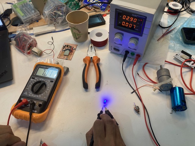
It is important to note that LEDs require a series limiting resistor to prevent excessive current and protect the LED.
<<<<<<< HEAD =======
To measure the consumption of devices, a multimeter can be used. The multimeter can measure resistance in ohms and provide a fixed voltage for battery testing. For example, when measuring a blue LED, it was found to consume 7.03 milliamps.
In the case of testing a servo using a Barduino (Arduino board), the Arduino Library code "sweep.io" was used. A servo is a motor that rotates parts of a machine with high efficiency and precision. The servo was connected to pin 13, ground, and power. It moved 1 degree every 5 seconds, waiting for 5 seconds before moving another degree. The voltage regulator for this setup had a total consumption of 3.3 volts, and the ESP32 (another type of microcontroller) could consume anywhere from 100 milliamps to almost 1 amp (900 milliamps). The standard voltage for USB A or B is 5 volts.
When calculating the total consumption, it's important to consider how long the device will be operating to determine the battery capacity needed. For example, a regular AA battery typically has a voltage of 1.5 volts and a capacity of 800 milliamp-hours (mA).
Measuring the consumption of the ESP32
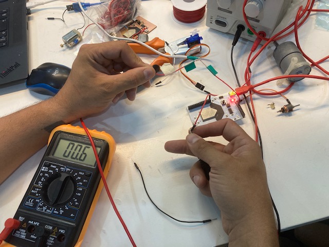
To measure the consumption of the ESP32 on the Barduino board, you need to connect the board to power and check the circuit passing through the 5V connector.
Measuring the consumption of the ....(can't remember the name of this)
To calculate the consumption of any load, it is necessary to embed the multimeter directly into the circuit (breaking the electrical circuit must be done before the start of measurements with the voltage turned off), observing the polarity, the voltage source ground is connected to the load ground, and the plus is connected to the multimeter built into the open circuit (that is, the multimeter is connected to the minus probe to the positive load).