Back To Top
Week 10 - Mechanical design and machine design
Brainstorming
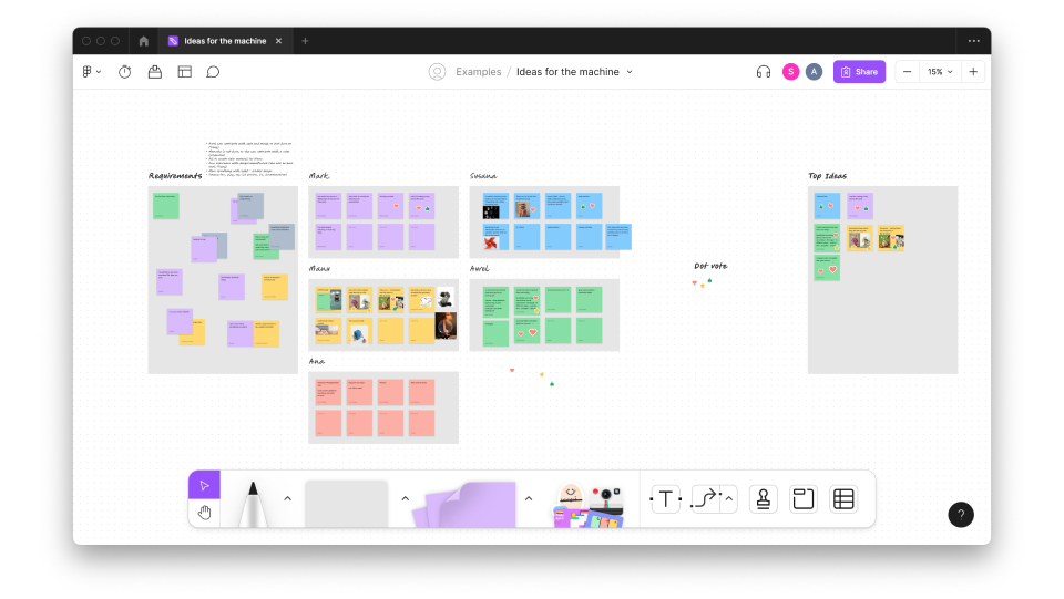
We started the project by gathering before and writing down our ideas. We first thought about our goals for the machine and who could contribute with what since we all have different skills.
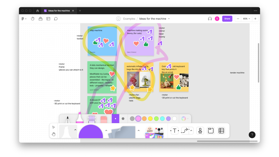
We thought we didn't want to do anything too big, or complex, but we also didn't want to waste material we were ok with doing something not worthwhile. We had many initial ideas but came down to 3 ideas/directions:
The general idea is to use a small piece of mirror catching angeled to its source of light or laser (better use directed on the mirror light, laser dangerous for cats). It should rotate or oscillate. Oscillation is probably better, because more randomized, also cats are fast, and even small mirrors have weight, so motors need both speed and torque. We might try to create oscillation using a mirror suspended on springs. The machine may stand on the corner or edge of the table, using an ultrasound distance sensor. Have 30-45 angles of catch depending on the distance.
Turning a computer mouse into a simple remote-controlled vehicle and controlling it with your mouse (cursor) position - either moving the mouse by defining a zone, relative to the screen (ie. moving the cursor to the top left corner of the screen moves the mouse to the "top left corner" of the zone) or mouse moves relative to its previous position.
Combining the plastic bag idea (blown up with the fan) with the idea of the slapping hand.
The concept
After reflecting together with the instructors and checking everything we had available at the lab we decided we wanted to experiment with the inflatable idea. We then brainstormed a bit more and created the idea of an "echo garden".
The "echo garden" works with air input, that passes through a tube and blows the flowers. The idea is that the garden flowers are connected to specific sounds - so when they are blown the sound made varies, we aimed to create this by using the idea of a flute in our mechanism.
Planning
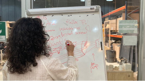
We started by thinking on how we could create the machine, considering all the material we had available. We though about what mechanism it would need and who could start picking what.
The inflatables
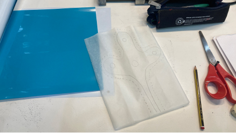
For the inflatables, we used heat transfer vinyl. We started by drawing the flowers that we would use to be filled in with air in our machine, already considering that the baker paper we are using would be the parts that the vinyl wouldn't stick to each other, making therefore possible to be an inflatable.
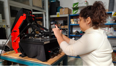
At the heat presser machine, we set the temperature to 255 celsius degrees and set up the time for around 3 minutes. Then we simply put the 2 pieces of vinyl together with the baker paper in the middle, the baker paper parts without it would be parts that would glue together. After the machine heated (we just waited the first 3 minutes) we pressed it again, but this time with the vinyl in the machine. Also, we made sure to use a sheet of baker paper between the machine and the vinyl so the melted glue doesn't stick to the machine.
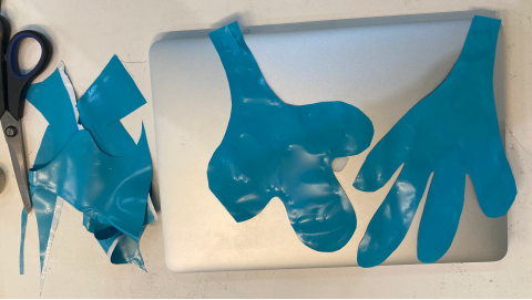
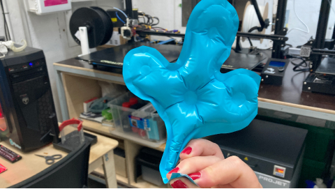
Once the vinyl was glued then we just cut the excess of material and with the hole left we could blow air into it!
The mechanics @ana
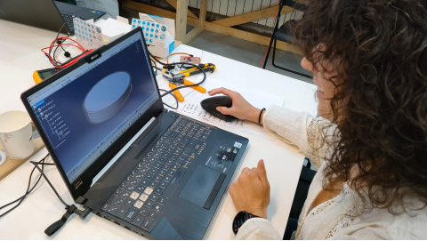
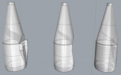
Catia V5 2022 was used to design the system.
First, a design was made to manufacture a scaled prototype. This was done because the final design of the product was very large, and to check the operation and fit of the parts we did not want to waste material.
The product mechanism should not be complex. It only requires a linear movement of the plunger inside our tube or flute.
There are different solutions for a simple linear movement. The most basic ones are:
- Worm screw
- Rack and pinion
- Rod Crank Mechanism
The rack and pinion mechanism was chosen because it is one of the simplest, it can be manufactured in 2D (flat parts) and the movement ratio is easy and direct.
A rack and pinion mechanism is a mechanical device with two gears, called "pinion" and "rack", that converts a rotary motion into a straight motion or vice versa. The circular gear called "pinion" meshes with a toothed bar called "rack", so that a rotation applied to the pinion causes the linear displacement of the rack.
The relationship between the pinion rotational speed (N) and the rack linear speed (V) depends on two factors: the number of teeth on the pinion (Z) and the number of teeth per centimeter of the rack (n).
For each complete revolution of the pinion, the rack will move forward by as many teeth as the pinion has. It will therefore move a distance (1) and the speed of the displacement will be (2):
d = z/n (1)
V = N·(z/n) (2)
If the pinion rotation speed (N) is given in revolutions per minute (rpm), the linear speed of the rack (V) is given in centimeters per minute (cm/minute).
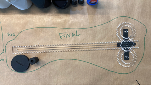
Based on this, the mechanism was designed with three 30-tooth pinions. The first one was directly rotating with the motor, and the other two were driven by the first one and in turn transfer the movement to the rack, each of them on one side of the rack, to provide stability.
ADD CAD IMAGE OF THE MECHANISM
Once the whole mechanism was designed, the parts were printed to see how the mechanism worked. PLA was used as the material, except for a rubber that adapts the plunger to the body of the flute, which was printed with TPU (Filaflex).
The flexible part, although it was printed correctly and worked halfway well, has too much contact area with the tube, causing too much friction and making it difficult to move the plunger. Therefore, the model had to be modified.
The pieces were sanded and some of them were glued to see the functionality of the mechanism.

A lot of friction was obtained between the 3D printed parts, although they fit together correctly. Thus, it was thought that perhaps laser cutting of acrylic material would improve the motion transmission of the most important parts of the mechanism (pinions and rack).
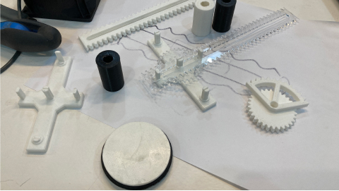
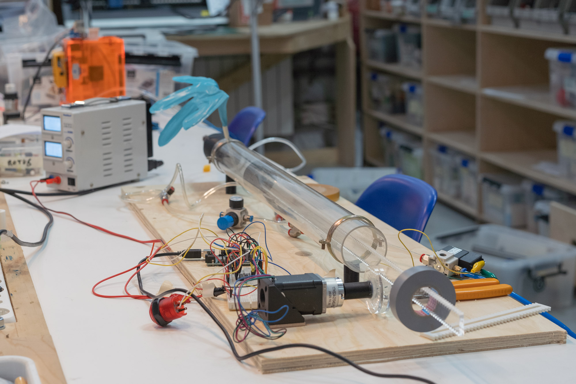
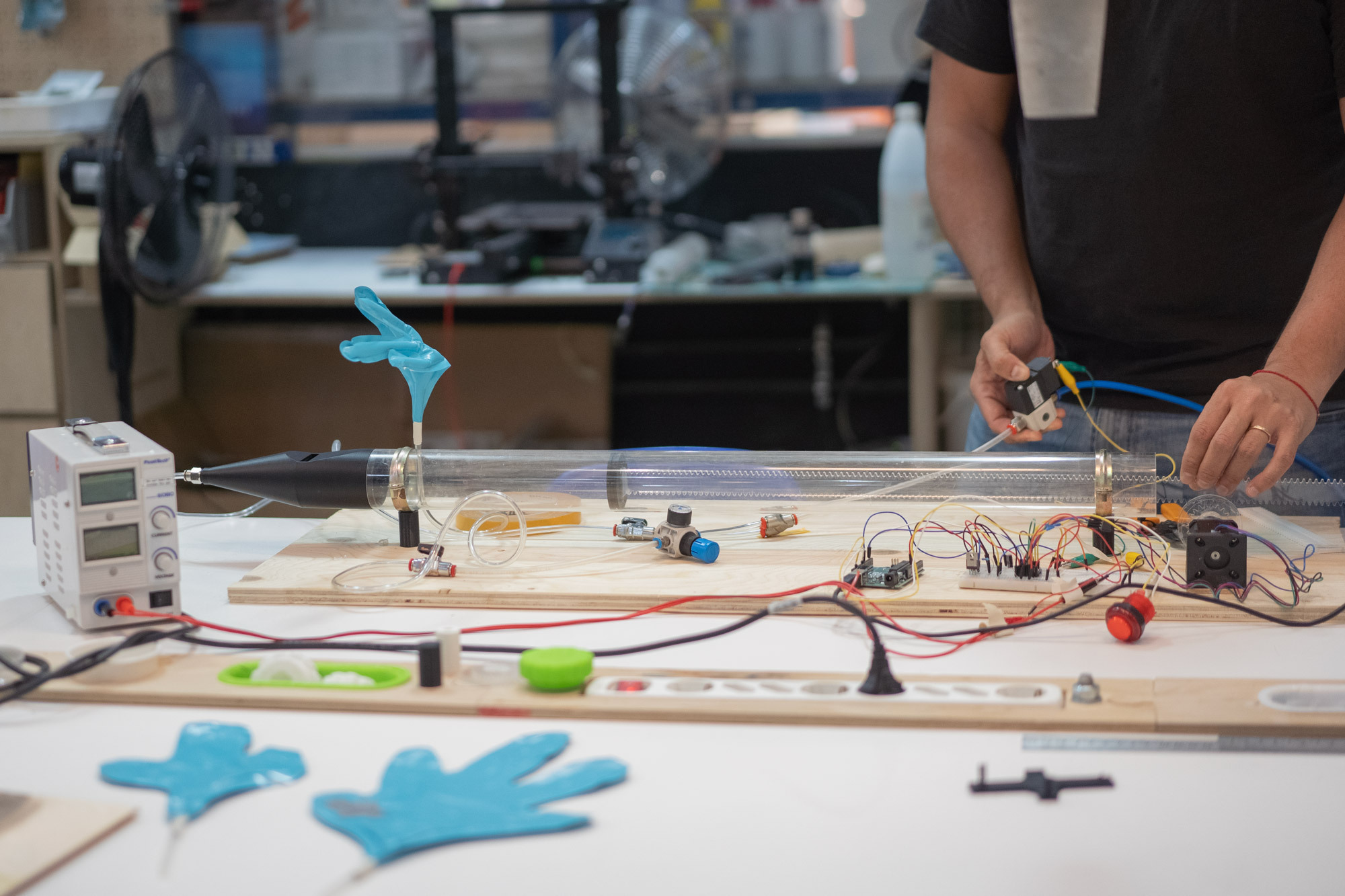
Thus, a prototype of the mechanism to be manufactured was obtained, which worked as shown in the video.
The rack would have the plunger (which in turn would be surrounded by the flexible part so as not to let the air escape) glued to one of its ends. The central pinion would be fitted (by means of a fitting piece) to the stepper motor.
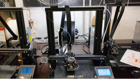
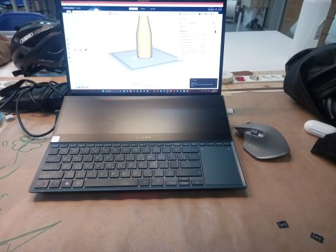
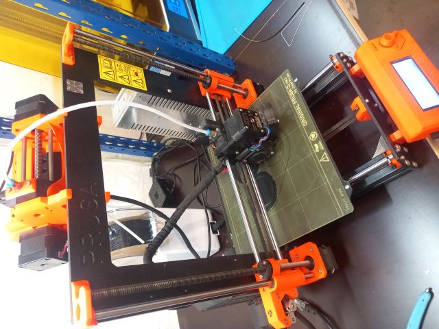
3D printing and laser cutting the final pieces for the mechanics
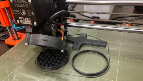
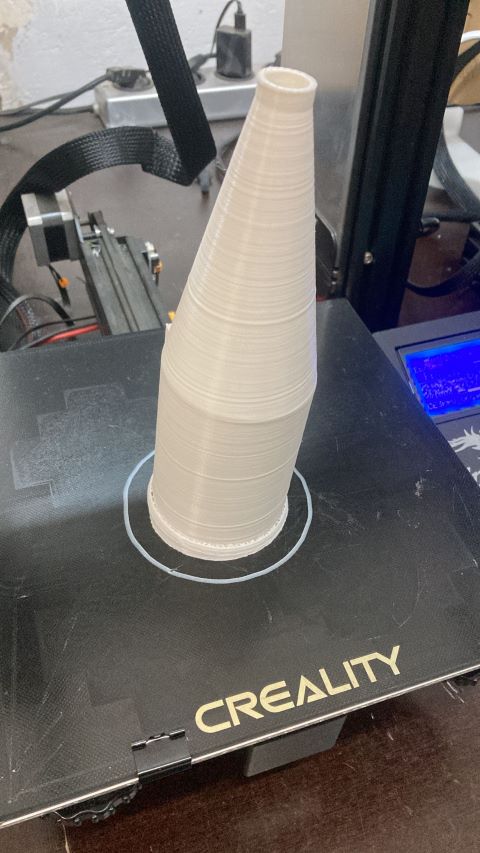
After we tested the first prototype it was time to 3D printing the final pieces. For the 3D printed pieces we used a temperature of 215 celsius degrees, the bed at 60 celcius degrees and a speed of 50 in a standard quality. We used the PRUSA machine.
For the other pieces we use the 5mm acrylic and laser cut the pieces. We made sure the files were correct (without any duplicated line) and set up the correct colors (black for raster, red for the first cut and blue for the second cut) and then used the command "print" to send it to the laser cut software. In there we defined the following parameters:
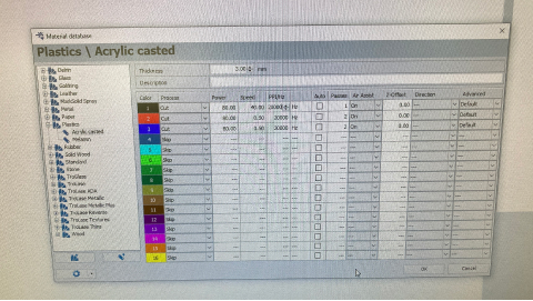
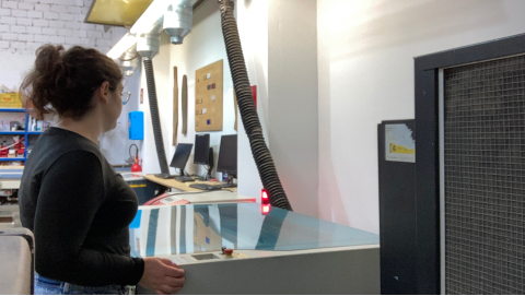
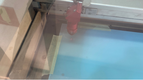
Once it was ready we calibrated the laser cut machine and added the acrylic with tap to the bed of the machine. Once everything was ready we connected the air extraction and send the job to the machine.
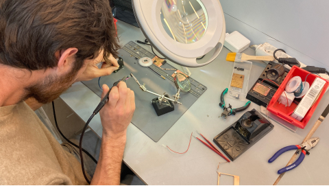
The whistle @marc
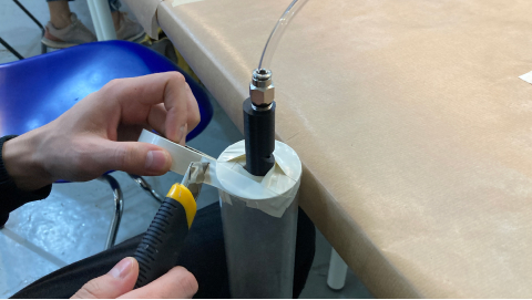
Relying on founded draw wistle was modeled and ptinted, but its tint was to high and sensitive.
To make it more tunable we tried to scale up inner hole (the outlet point of the injected air) and scale down width of air cutter excise. In result scaled up did not work well, scaled down became lower and less sharply rising, but still not well manageble.
Concluded that need try to scale wistle referencing to acrilic tube volume and diameter, so shifted from wistle to organ contruction.
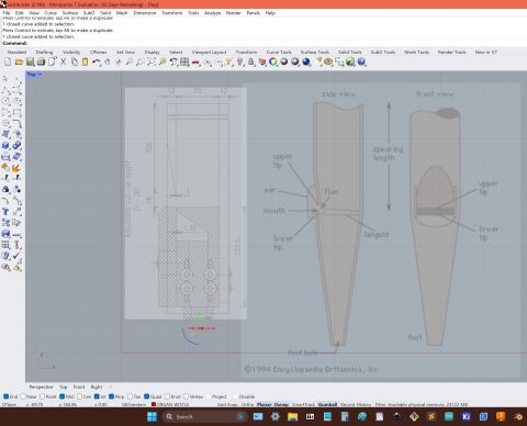
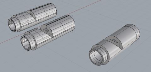
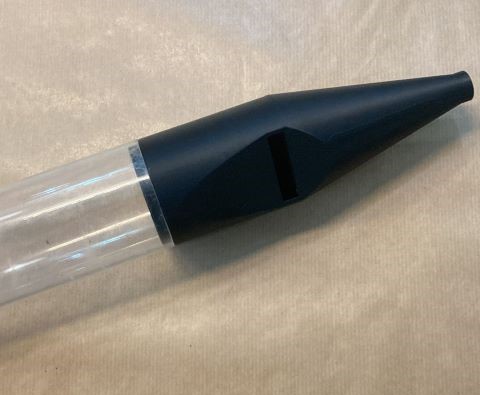
Exist 2 organ pipes types according to the principle of sound extraction: Reeds and Labial. Labial (reference) have differenses in constuction, so few refences were used.
Detail have cone part with expansion, bending wall for air flow smoothness and outlet crevice ( 1.35 mm ), second part is tube with rectangular hole and blade.
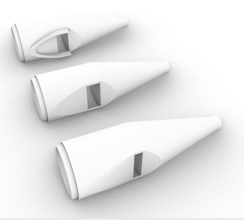
Tried two modifications: ears (concentrating external air flow) and smaller blade-crevice distance ( 18 mm -> 9 mm ).
Was used tree type supports to reduce consumption of material, wall layers count changed (2 -> 4) to make wall ( 2 mm ) more solid, safer and probably better for resonation.
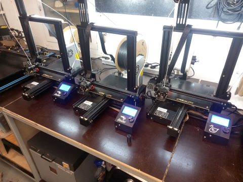
Used three less collibrated printers for spare print.
Printed well, fits accurate, sounds deeper and smoothier.
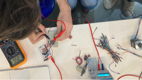
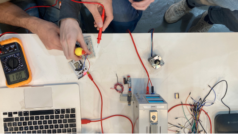
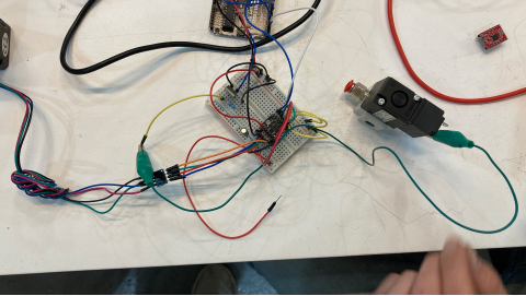
The code and electronics
The electronics for our machine consisted of 3 parts:
- Pressing a button
- Turning the stepper motor
- Activating the solenoid valve
We started by deciding which board to use for our project and ultimately settled on an Arduino
UNO for the sake of simplicity (the documentation we were using as a reference had been made
with an Arduino UNO). For the motor we chose to work with a NEMA 17 stepper motor and a A4988
Driver Module.
Control
Stepper Motor with A4988 Driver Module & Arduino
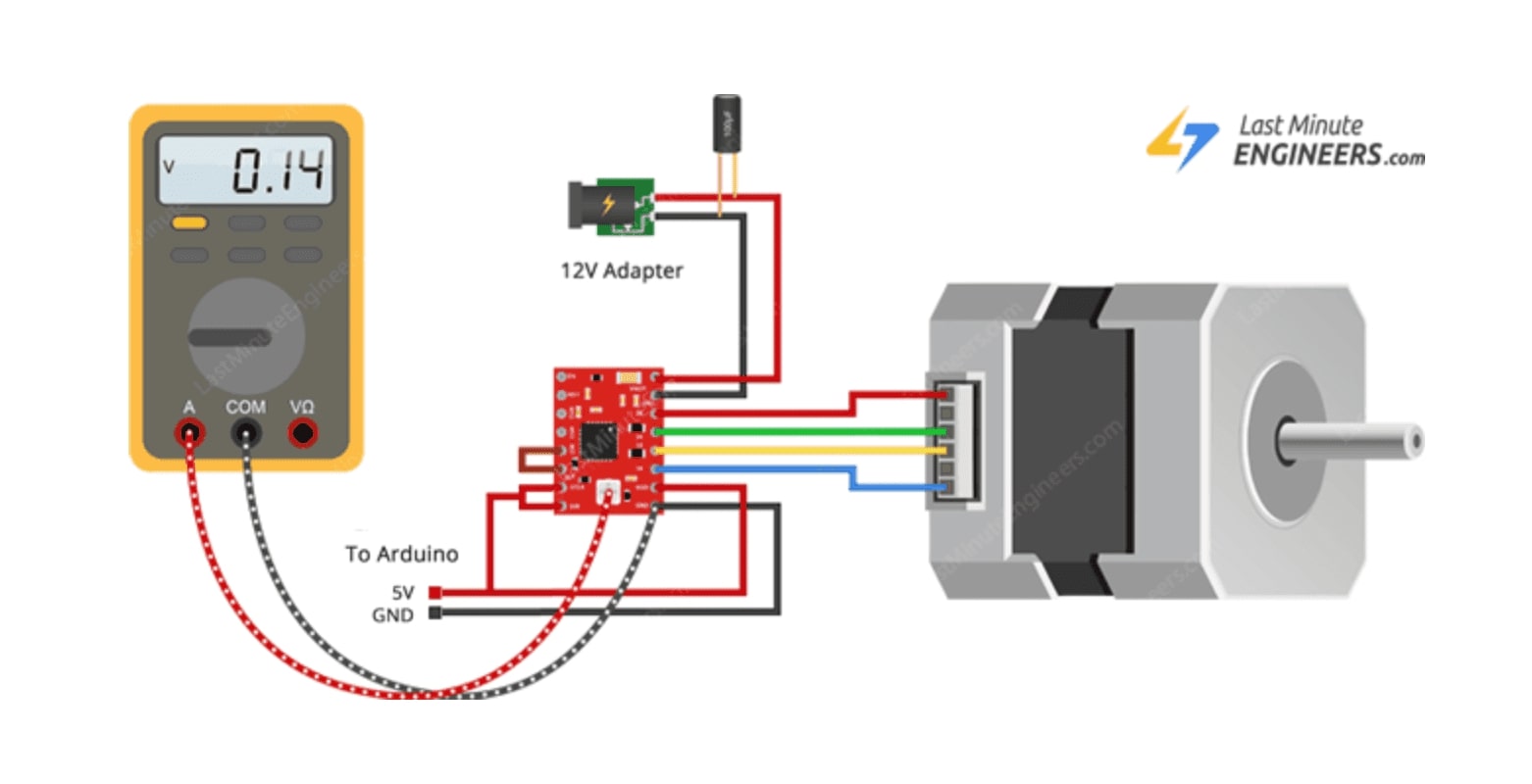
The diagram above was essential to helping us connect to motor, driver and Arduino correctly
aswell as setting up the current limit correctly as we were following the exact same setup.
Here it is showing how adjust the potentiometer in order to setup the current limit, following
this formula:
(350mA / 2.5 = 0.14V)
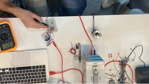
Once the motor was setup, we tested it using a simple script to make sure the motor could move
in both directions correctly.
motorTest.ino
After that we had to tackle the second part of the electronics: the solenoid valve. The aim was to use the valve to control the air flow. The valve only has the capacity to be OPEN or CLOSED, it cannot be used to regulate the amount of air flow. In order to function it needs 12V, like the steppermotor, and a Mosfet.
the Mosfet
The mosfet is the component that allows us to control the state of the valve with the Arduino,
whilst the power is provided by an external 12V power source.
We used a N-channel mosfet and set it up following the diagram below:
The way we want our project to work can be broken down into a few simple steps:
- Press the button to start recording (starts a timer)
- Release the button to stop recording (stops the timer)
- Voice data is read and translated into a positional value for the stepper motor [WIP]
- Stepper motor moves to specific position to recreate voice pitch
- Valve opens for the amount of time saved in the timer
- Instrument plays the "echo of the voice"
Here is the relatively simple script we developed to control all these electronics components
following the steps defined above.
echo_garden.ino