Back To Top
Week 11 - Input devices
Measuring input devices
For this week's assignment we measured the signal produced by the signals of input devices. We check a blinking LED just to test and then we measured the consumption of a potentiometer and a temperature sensor using a multimeter and an oscilloscope. What we measure in an input device to check its consumption is the resistance - ohms. By knowing the resistance we know how much an input device is consuming.
Measuring a led blinking (to test the oscilloscope)
To measure the blinking of an LED on the oscilloscope we first configure the basic settings of the oscilloscope, such as the time scale and voltage scale, according to the characteristics of the LED and the expected signal.
Then, we connect the anode (positive) of the LED to a power supply and the cathode (negative) of the LED to the input channel of the oscilloscope.
We then adjusted the voltage scale of the oscilloscope's input channel so that the LED signal was clearly visible on the screen. This allowed us to measure the amplitude of the signal.
We then adjust the time scale of the oscilloscope to see several complete cycles of LED flashing on the screen. We were then able to measure the period of the signal.
We observe a waveform corresponding to the flashing LED on the oscilloscope screen. The signal oscillated between a low level (off) and a high level (on) while the LED blinks.
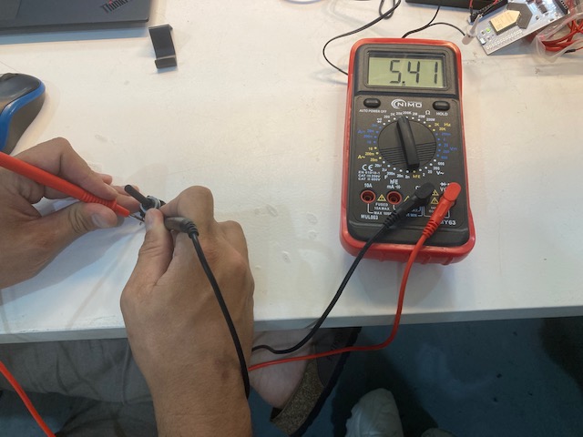
Measuring a potenciometer
Some potentiometers have a variable resistance across their range and may have specified minimum and maximum resistances. We can check if the potentiometer is operating within limits by measuring the resistance at different positions of the control and comparing the readings with the manufacturer's specifications.
First, we turned the multimeter on to the proper setting for measuring resistance (Ω) and selecting the scale.
Then, with the potentiometer disconnected from any power supply, we connected the multimeter test leads to the potentiometer ends. The red lead is connected to the end of the potentiometer with the higher voltage connection, while the black lead is connected to the end of the potentiometer with the lower voltage connection.
Once the leads are correctly connected, the multimeter displayed a resistance of the potentiometer on the display. If the potentiometer is a linear model, the measured resistance should be relatively constant as you turn the potentiometer dial. If the potentiometer is a logarithmic (audio) model, the resistance may change non-linearly.
Finally, we varied the potentiometer control and observed how the resistance reading on the multimeter changed. We saw that the measured resistance varied as we adjusted the potentiometer.
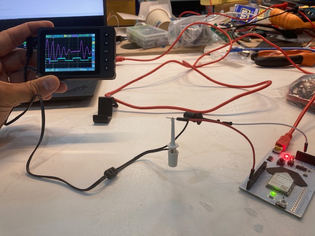
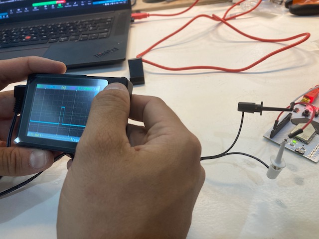
Measuring a distance sensor
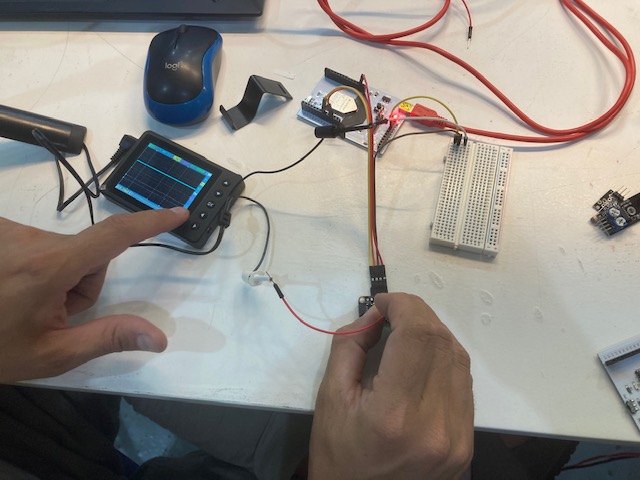
The basic principle of operation of optical distance sensors is based on measuring the speed of the beam (laser or LED), which is reflected from a special reflective mark located on the object, or directly from the object itself (triangulation). By connecting an oscillometer in parallel and adjusting the display, you can see the changing flow of the incoming signal, thus correlating and analyzing the frequency, time and logic compliance with the expected performance, you can determine whether the device is working correctly or is a source of errors.