Back To Top
Week 13 - Networking and communications
Using the MQTT protocol to send a message from different clients
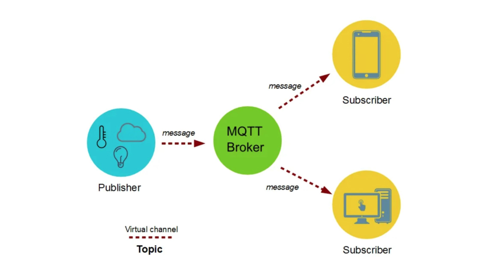
What is the MQQT?
MQTT is a standards-based messaging protocol, or set of rules, used for machine-to-machine communication. Smart sensors, wearables, and other Internet of Things (IoT) devices typically have to transmit and receive data over a resource-constrained network with limited bandwidth (aws.amazon.com).
How does it work?
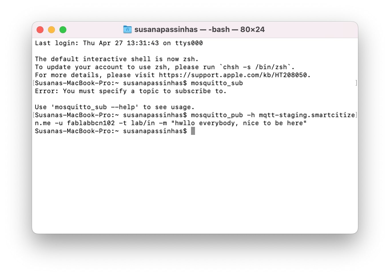
It works by having a broker managing all the messages coming to it. It receives them and then sends them to the clients assigned to it. To send messages to the broker we need to define which topic the clients are subscribed to. We can set up this when we create the connection to the broker. We can do this connection using the terminal to download mosquitto and then use it to send messages to the broker as long as we have the IP of the service, and we set up the user, password and message.
Using the ESP32 wifi to connect to MQTTTo reveive the messages (and see them) we can use the ESP32 microcontroller wifi feature to connect to the broker through a serial port, in this was we can receive the messages in the Arduino IDE serial monitor.
03
I2C Protocol
For the test I used this protocol, for multiple digital slave to communicate with the master. It is for short distances communications.
So for the test i'm using a Barduino acting as the master in an I2C communication with a slave device, in this case my PCBoard with a phototransistor. So is to requesting data from the slave device and control an analog output based on the data that is receiving.
When open arduino, keep in mind to change the serial configuration to "ONE_UART_ONE_WIRE_NO_SPI" this means ne one-wire interface
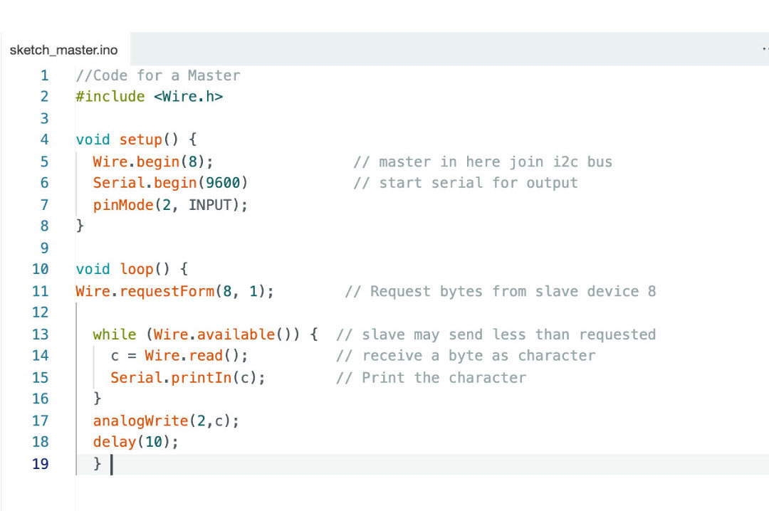
For the master code it needs to start with: "#include
Then in the setup(), it says the barduino to start on, then with wire.begin at 8 and for serial communication the baud rate(rate at which data is sent) of 9600, lastly, writing what is the pin output (in my case 2)
In loop(), its requesting to the slave device with the adress 8 asking for 1 byte of data. so it checks if there is data from the slave, if the answer is yes, then it reads it and stores it in "C" then using the serial monitor it prints it. Then, with analgWrite we set up the output on pin2 and a 10 delay before it repeats the loop.
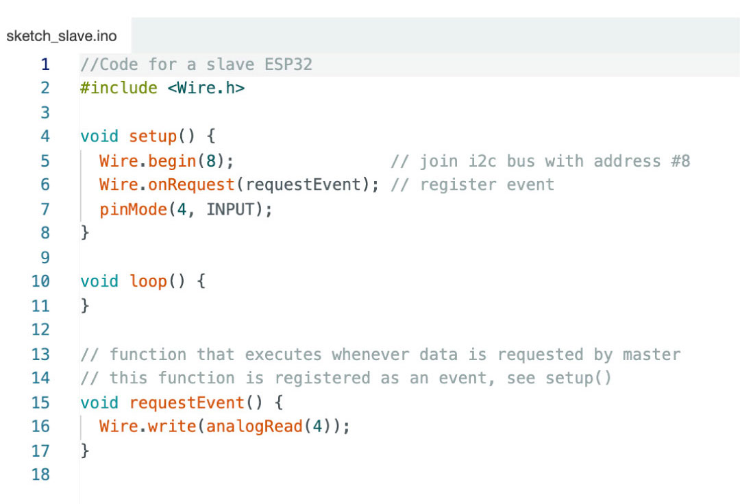
For the slave code, i'm using the ESP32 in my board so it needs to responde to the I2C master by sending the analogue reading from pin4.It also needs to start with the "#include
Then in the setup(), after start the communication as a slave, it reads the adress 8 (in the channel that they are communicating with wire.begin). Then it handles with the event whenever the master request data from this board. Lastly, the pin also needs to be in 4.
In loop(), the slave ESP32 is waiting for requests from the master and doesn't need to loop any task.