10—Output Devices
Assignment
- Group assignment:
- Measure the power consumption of an output device.
Our goal is to measure the power consumption of an output device.
As an example, we used a Barduino microcontroller on a breadboard, connected to a resistor and an LCD 1602 display. We compiled and uploaded code to confirm the LCD was working correctly—a message successfully appeared on the screen.(Example code given by DFRobot)
#include <Wire.h>

/*!
 * @file Fade.ino
 * @brief Fade.
 * @copyright	Copyright (c) 2010 DFRobot Co.Ltd (http://www.dfrobot.com)
 * @licence     The MIT License (MIT)
 * @maintainer [yangfeng](feng.yang@dfrobot.com)
 * @version  V1.0
 * @date  2021-09-24
 * @url https://github.com/DFRobot/DFRobot_RGBLCD1602
 */
#include "DFRobot_RGBLCD1602.h"

/*
Change the RGBaddr value based on the hardware version
-----------------------------------------
       Moudule        | Version| RGBAddr|
-----------------------------------------
  LCD1602 Module      |  V1.0  | 0x60   |
-----------------------------------------
  LCD1602 Module      |  V1.1  | 0x6B   |
-----------------------------------------
  LCD1602 RGB Module  |  V1.0  | 0x60   |
-----------------------------------------
  LCD1602 RGB Module  |  V2.0  | 0x2D   |
-----------------------------------------
*/
// Define custom SDA/SCL pins (adjust GPIO numbers to match your board)


DFRobot_RGBLCD1602 lcd(0x60, 16, 2); // I2C address, 16 columns, 2 rows


void breath(unsigned char color){
    for(int i=0; i<255; i++){
        /**
         *  @brief set backlight PWM output
         *  @param color  backlight color  Preferences:REG_RED\REG_GREEN\REG_BLUE
         *  @param pwm  color intensity   range(0-255)
         */
        lcd.setPWM(color, i);
        delay(5);
    }

    delay(500);
    for(int i=254; i>=0; i--){
        lcd.setPWM(color, i);
        delay(5);
    }

    delay(500);
}

void setup() {
  Serial.begin(115200); // Initialize serial communication
  Serial.println("Upload successful! Code is running.");

    /**
     *  @brief initialize the LCD and master IIC
     */
    lcd.init();
    // Print a message to the LCD.
    lcd.print("Happy birthday yo");

}

void loop() {
    // RGB use
    breath(lcd.REG_RED);
    breath(lcd.REG_GREEN);
    breath(lcd.REG_BLUE);
    // Monochrome use
    //breath(lcd.REG_ONLY);
}
Voltage Measurement (using a parallel method):
The circuit was built in a series configuration, meaning the components (resistor, LCD, etc.) were connected one after the other in a single path: 3.3V (VCC) to resistor to LCD to GND
To measure voltage, however, we must connect the multimeter in parallel to the component we're measuring. This is because voltage represents the difference in electrical potential between two points.
We set the multimeter to DC Voltage (V) and left the circuit fully connected.
• The red probe was placed on the LCD’s anode (still connected to the resistor).
• The black probe was placed on the LCD’s cathode (connected to GND).
With a green LED, we measured a voltage drop of approximately 2.0V across it.
To measure the supply voltage (VCC), we placed the red probe on the 3.3V pin of the Barduino and the black probe on GND, reading a value of 3.17V.
This demonstrates how a multimeter reads the "electrical pressure" between two points—i.e., voltage.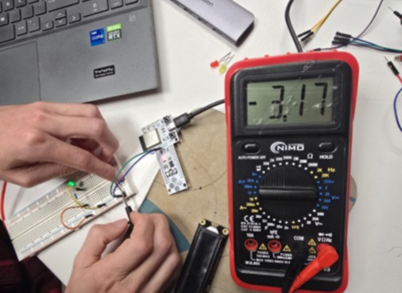
Next we tasked ourselves with measuring the Current using a series method.
To measure current, we must place the multimeter in series with the component we’re measuring. That means we need to temporarily break the circuit and insert the multimeter so that all current flows through it.
We set the multimeter to DC Current (A or mA) and moved the red probe to the correct port for current (either 10A or mA, depending on expected flow).
To measure the current flowing through the LCD:
• We disconnected the wire between the resistor and the LCD’s anode.
• Then we connected the red probe to the resistor output (where the LCD’s anode was connected) and the black probe directly to the LCD’s anode.
The current now flowed like this:
VCC to resistor to multimeter to LCD to GND
With the multimeter now part of the circuit, it was able to measure the full current flowing through the LCD.
We expected around 15–20 mA, and our reading confirmed this: 20 mA.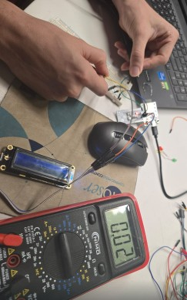
Finally if we want to calculate Power, we use the equation (P = V × I):
To calculate power consumption:
Power (Watts)=Current (Amps)×Voltage (Volts)\
Current (Amps)} x Voltage (Volts) = 0.02 A×3.17 V= Power 0.0634 WattsSo, the LED circuit is consuming approximately 63 milliwatts.
- Document your work on the group work page and reflect on your individual page what you learned.
- Measure the power consumption of an output device.
- Individual assignment:
- Add an output device to a microcontroller board you've designed and program it to do something.
00— Reflection
It went well we tested several different sensors.
01—DC Motor (brushed)
For the DC Motor we just used a simple MOSFET circuit that was provided in one of the diagram on the IAAAC Fab Barcelona website.
- First we followed this diagram
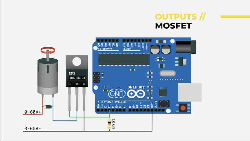
- This was the circuit on the breadboard below using the 30N06LE and the Barduino.
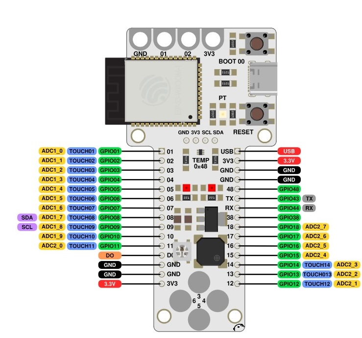
- Below is the final code we used it took several attempts to get the code to work do to simple errors. We also had originally written as a simple LOW/HIGH loop with a delay until we realized it needed to run on a PWM capable pin on the Barduino and the code need to use PWM syntax. Below is the Barduino pinout we refferenced as well as the arduino code used.
void setup() {
  pinMode(5, OUTPUT); // Use PWM-capable pin like 5
}

void loop() {
  for (int i = 0; i <= 255; i++) {
    analogWrite(5, i); // Increase brightness
    delay(10);
  }
  for (int i = 255; i >= 0; i--) {
    analogWrite(5, i); // Decrease brightness
    delay(10);
  }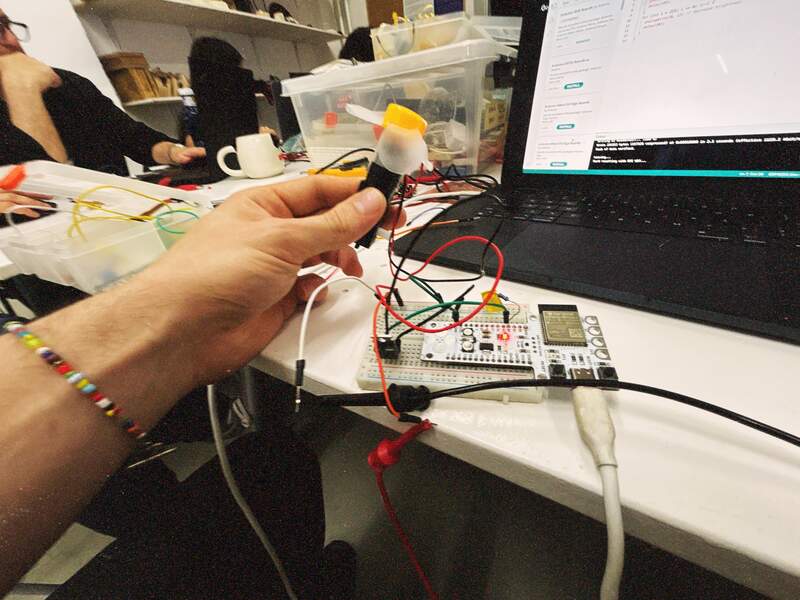
}- Final result and a recording of the varying power consumption likely as a result of the higher power input as the motor starts up for each cycle. Consumption of current is ~.4 mA →130mA.

`