12— Mechanical Design, Machine Design
Assignment
- Group assignment:
- Design a machine that includes mechanism + actuation + automation + application
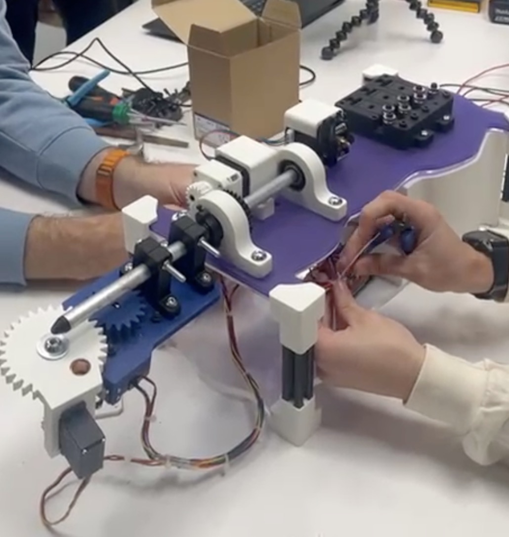
- Build the mechanical parts and operate it manually
- Document the group project
Requirements
Shown how your team planed allocated tasks and executed the project (group page)
Described problems and how the team solved them (group page)
listed possible improvements for this project (group page)
Included your design Files (group page)
Include 1 min video
00—Final Project Video
Link to final Project Video
01—About the Project
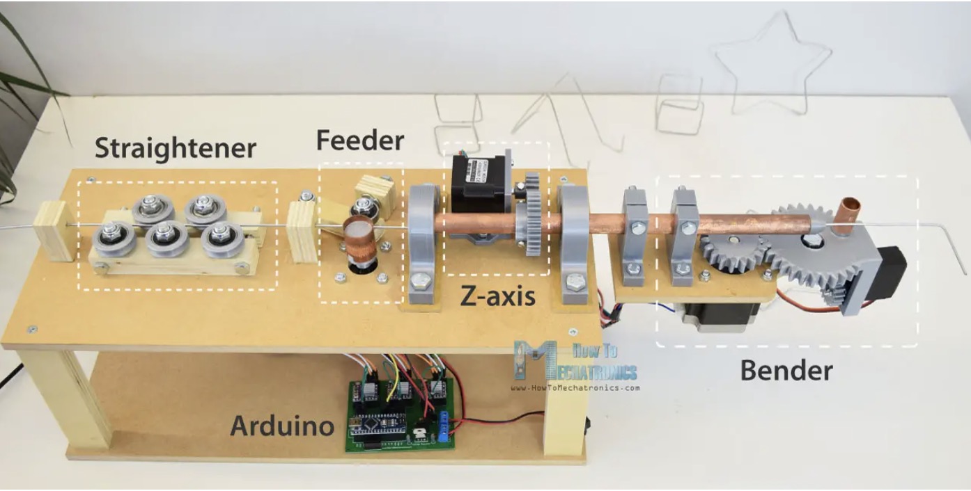
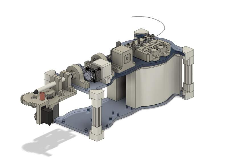
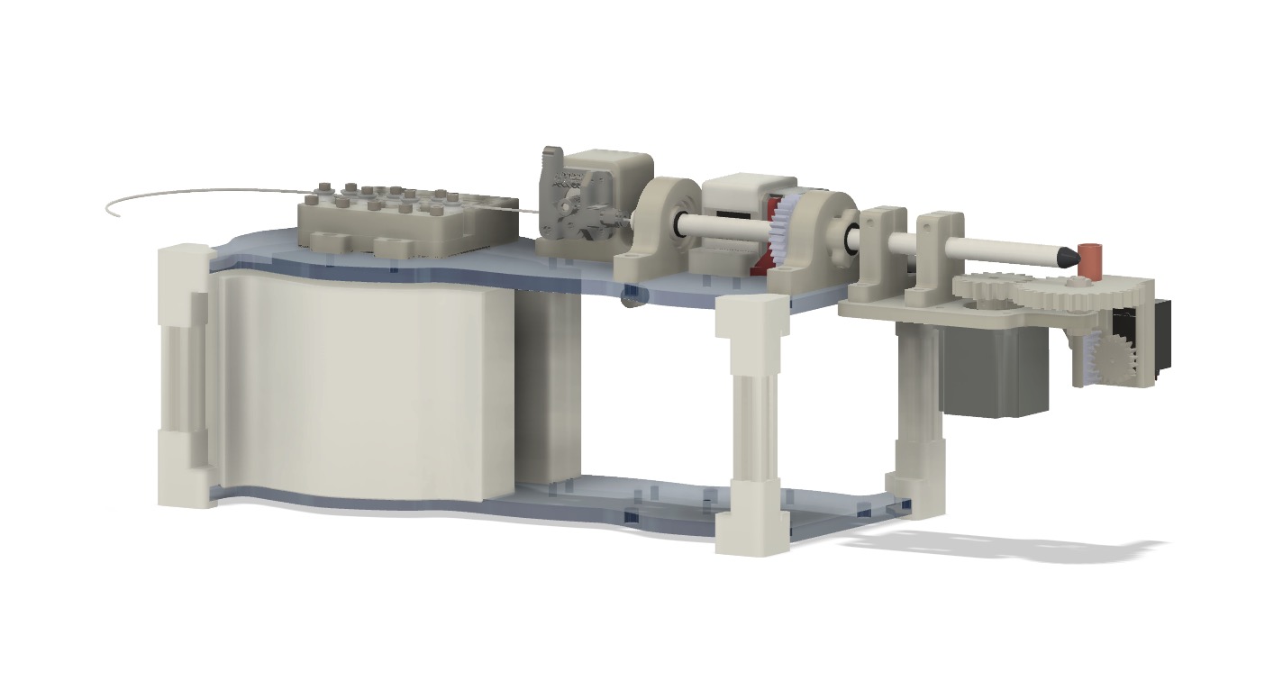
As a group we chose the CNC wire bender project because we felt that it created a lot of interesting possibilities as a tool. Some of the ideas we had were to create circuit sculptures using thin brass rod or hanging sculptures/ mobiles. The design we chose also had good documentation and included a tutorial with a full assembly .step file. Since the design was well documented we felt like it we felt it made sense to build it “as is”. After creating the first version from the plans we planned to take a phased approach in line with the spiral development ethos— producing a working project at the end of each phase. Below is the original design we started with, a link to the documentation can be found here . This original step file was used as a reference when creating the final assembly Fusion file.
Link to original project writeup
Link to original CNC wire bender CAD files
02—Initial Project Planning and Allocation of Tasks
In Brief: From the beginning we broke the project into several distinct spirals. After the first spiral the Engineered CAD and the electronics as separate teams that could work mostly independent from each other. To organize our roles Katya made a multi page spreadsheet that organized BOM, progress, and project roles. That can be found here. Below is an overview of what we had originally planned to execute for the project. Minor changes were made to each spiral at the beginning of each phase.
Spiral 1—Manual test with unpowered machine
- Assemble the machine as quickly as possible by closely following a slightly modified version of the original design.
- Eliminate parts of the original design that are non essential (feeder and straightener).
- Convert difficult to create wooden parts to 3D printable plastic parts.
Spiral 2—Prototype electronics + essential mechanical
- Electronics
- Get electrical system up and running + run steppers with simple code — Ed and Gonzalo
- Modify custom board KiCAD so it is ready to machine on the Roland SRM-20— Katya
- Refine software control system so that the motors have correct bend calibration— Ed and Gonzalo
- Mechanical CAD
- Redesign and add feeder back into the design —Andrew
- Fix the lateral position of copper feeder tube with custom 3D printed collar—Andrew
- Overhaul all elements needed to change the feeder tube to the more rigid narrower aluminum feeder tube —Andrew
- Spool feeder prototypes— Mark
Spiral 3— aesthetic + mechanical + custom milled PCB
- Full visual/industrial redesign in Blender—Camila
- Re-engineered stepper planetary reduction— Edward and Andrew
- Engineered CAD rework for new industrial design — Andrew
- Redesign fastener alignment holes for acrylic plates
- Redesign of counterweight system
- Redesign of 2020 corner pieces
- Get electrical system back up and running— Gonzalo and Edward
- Full production of custom PCB— Katya
- Laser cutting— ED, Mark, Andrew
- Final assembly— Mark, Andrew, ED, Katya, Camila, Gonzalo
03—Full Project Development Log
Spiral 1: Manual Test With Unpowered Machine
Recap
This first step actually proved to be pretty straightforward. As a group we all read through the original documentation then ED and Mark 3D printed all of the original 3D printed components. Andrew then reworked several of the components to be printable instead of wood fabricated. Mark put together a list of fasteners and Gonzalo and Andrew then purchased the fasteners and assembled the machine. Not a lot of road blocks with this first phase especially because we were not too concerned with getting the electronics working.
Detailed summary of design changes
- Tricky to recreate wood parts were redesigned to 3D printable parts— Andrew
- New 3D printable wire guide
- New 3D Printable Wire straightener base plate 2
- Decreased pillow block diameter for bearing press fit [from 35.4 nominal → 35.1] + Integrated wooden pillow block offset component
- Simple redesign of wire feeding mechanism using off the shelf ender filament extruder—Andrew
- Lengthen all motor wires so they can reach control hub— Camila
- Quickly assembled project — Gonzalo and Andrew
- Create initial BOM to purchase Fasteners (final updated BOM at end)— Mark
Spiral 2: Prototype Electronics + Mechanical Overhaul
Recap
This spiral was a full design sprint on all fronts. In a way it was multiple parallel sprints. This second version of the design did not get fully built from the engineered CAD on the left. New components were added into the design while simultaneously the electronics and software were improved.
Detailed summary of design changes
- Mechanical Design Changes
- Improved all component press and slip fits—Andrew
- New base for feeder assembly—Andrew
- Lateral collar with sleeve and set screw —Andrew
- Straightener assembly—Andrew
- Rear weight system —Andrew
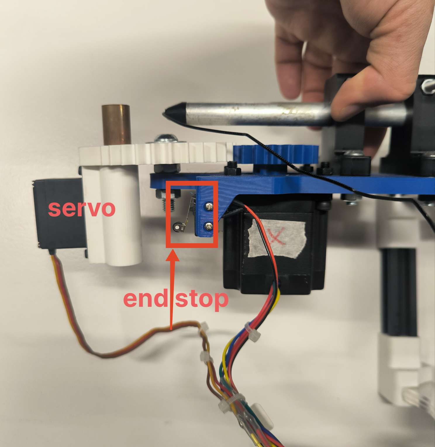
- Limit switch mount addition to bender gear plate—Andrew
- Redesign and add feeder back into the design —Andrew
- Fix the lateral position of copper feeder tube with custom 3D printed collar—Andrew
- Overhaul all elements needed to change the feeder tube to the more rigid narrower aluminum feeder tube —Andrew
- Spool feeder design and 3D print— Mark
- Electronics
- Get electrical system up and running + run steppers with simple code — Ed and Gonzalo
- Modify custom board KiCAD so it is ready to machine on the Roland SRM-20— Katya
- Refine software control system so that the motors have correct bend calibration— Ed and Gonzalo
Spiral 3: Aesthetic + Mechanical + Custom Milled PCB
Recap
This was the final sprint. Camila created a new design identity for the machine and as a group we worked to implement the redesign as well as incorporate a few key additions like the planetary reducer. The Planetary gear reduction was Eds solution to fixing an issue where that we were having where the Z axis would not rotate. Thankfully we were able to get everything finished on time, but unfortunately we could not get the machine working again. We were plagued with many difficult to solve issues with the stepper controller system that we still have not been able to fully resolve. An
Detailed summary of design changes
- Full visual/industrial redesign in Blender—Camila
- Re-engineered stepper planetary reduction— Edward and Andrew
- Engineered CAD rework for new industrial design — Andrew
- Redesign fastener alignment holes for acrylic plates
- Redesign of counterweight system
- Redesign of 2020 corner pieces
- Get electrical system back up and running— Gonzalo and Edward
- Full production of custom PCB— Katya
- Laser cutting— ED, Mark, Andrew
- Final assembly— Mark, Andrew, ED, Katya, Camila, Gonzalo
04— Final Thoughts + Improvements
All in all, the development of the Super Chena 5000 CNC was a worthwhile process. Unfortunately… heartbreakingly we could not get the full machine working at the very end for issues with the stepper control system. However I think we were all proud of how much we were able to learn and accomplish in just a two week period. There are many many changes that could be made with the design. I think it could even be worth starting with a blank sheet design. However, if we were to continue with the same architecture below are a few common sense changes.
- New control electronics— Instead of using a custom electronics setup you could use a prebuilt stepper control board used for 3D printer and run tests using Klipper. I think this would allow us to get up and running again and then we could likely reload and debug our GRBL program on this new hardware setup.
- Improve rigidity— The front pipe sags just a bit and the Z axis motor mount needs to be strengthened so the gear head stays meshed with rod mounted gear, the multilayered acrylic should be changed to thicker single layered acrylic.
- Feeder system— The feeder system does not always grip the wire. It would be better to limit the machine to only work with certain wire stocks. Additionally using a harder material (instead of brass) for knurled extruder gear would improve grip.
05— Making the Machine: Control Hardware + Software
In Brief: Below is a detailed breakdown of all relevant details regarding the electronics hardware and software and how to configure them to build your very own SUPER CHENA 5000 CNC.
Stepper Motor, Driver and Operation
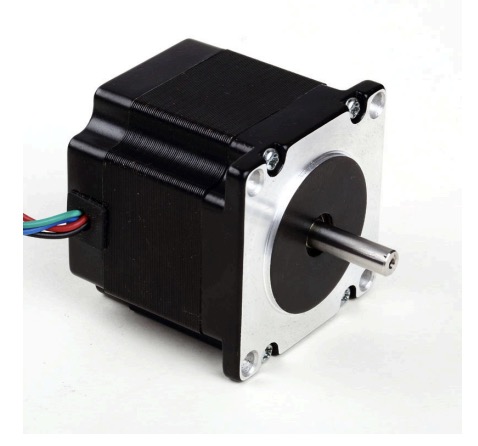
The motors we are using are
- 1x LDO Motor - 1.8 Hybrid Stepper Motor LDO-57STH56-2804A #210719. The datasheet can be found here https://ldomotors.com/uploads/product_attachment/path/8/LDO-57STH_Info_Sheet.pdf.
- 2x 42BYGH40-1.8-23A along with its datasheet https://mecheltron.com/sites/default/files/webresources/MechanicalElectroMech/StepperMotors/pdf/42BYGH_data_sheet.pdf
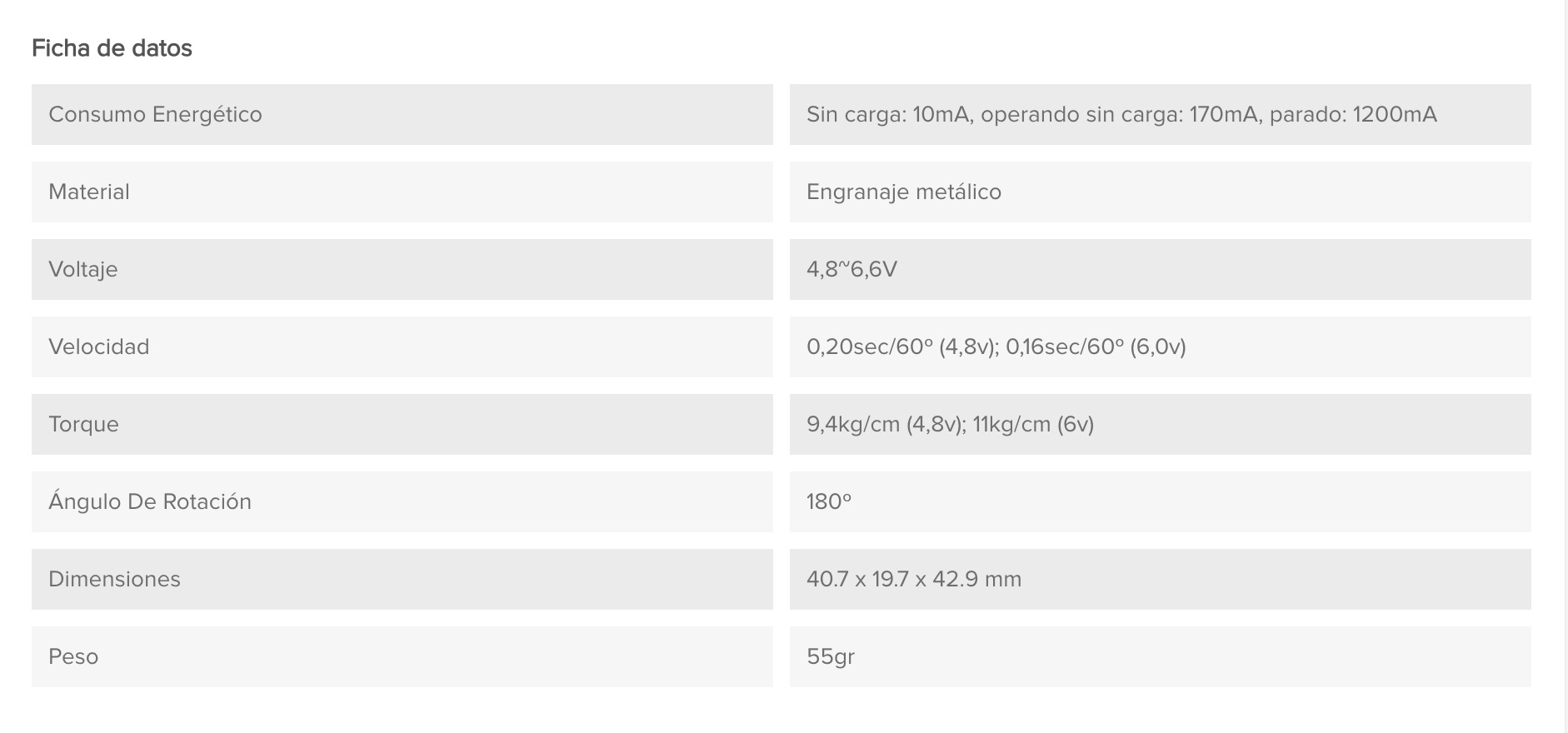
- SERVOMOTOR DIGITAL MG995 in stock so we will use it in our project. The data sheet can be found here. Some of the key features of the motor are given in the table below:
Setting up the Stepper Motor using a CNC Shield
References
[1] G-code cheat sheet : https://www.probotix.com/gcode_cheatsheet.pdf
[2] Marlin Gcode docs : https://marlinfw.org/docs/gcode/G000-G001.html
[3] GRBL error codes : https://resources.sienci.com/view/gs-grbl-alarm-error-codes/
[4] https://hackmd.io/@MikelLG/Bk0Ok4t61x by Mikel Llobera Guelbenzu to give the PI serial communication - GRBL description to help us define motor movements.
[5] https://cool-emerald.blogspot.com/2021/04/drawbot-xy-plotter-with-arduino-grbl.html
[6] https://www.diyengineers.com/2023/01/05/grbl-with-arduino-cnc-shield-complete-guide/
We decided to use the GRBL library from Marlin Firmware for controlling the stepper motors on the CNC shield. https://github.com/gnea/grbl/blob/master/README.md
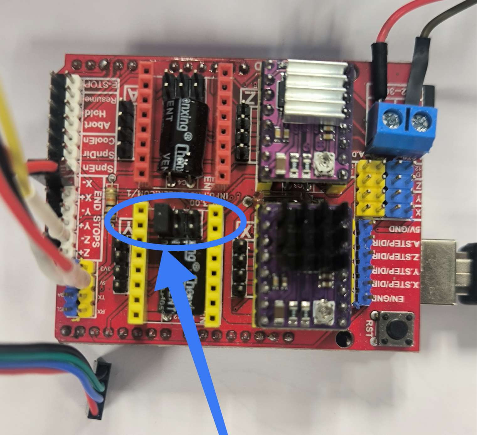
We followed the following guide to setup the motors https://www.diyengineers.com/2023/01/05/grbl-with-arduino-cnc-shield-complete-guide/ [6]
According to [5] cloned CNC v4 shields are known to have hardware issues.
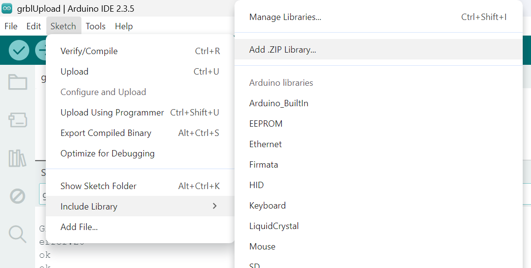
We downloaded the grbl-master file from github, then had to rezip the grbl library within on its own to then import it in Arduino IDE :
We then had to modify the config.h for our design following the steps described in [5]. The difference between the original and modified files is highlighted in the screenshots below.
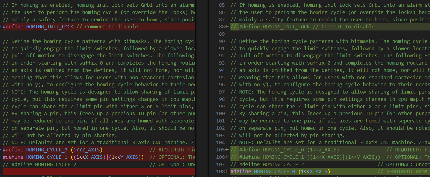
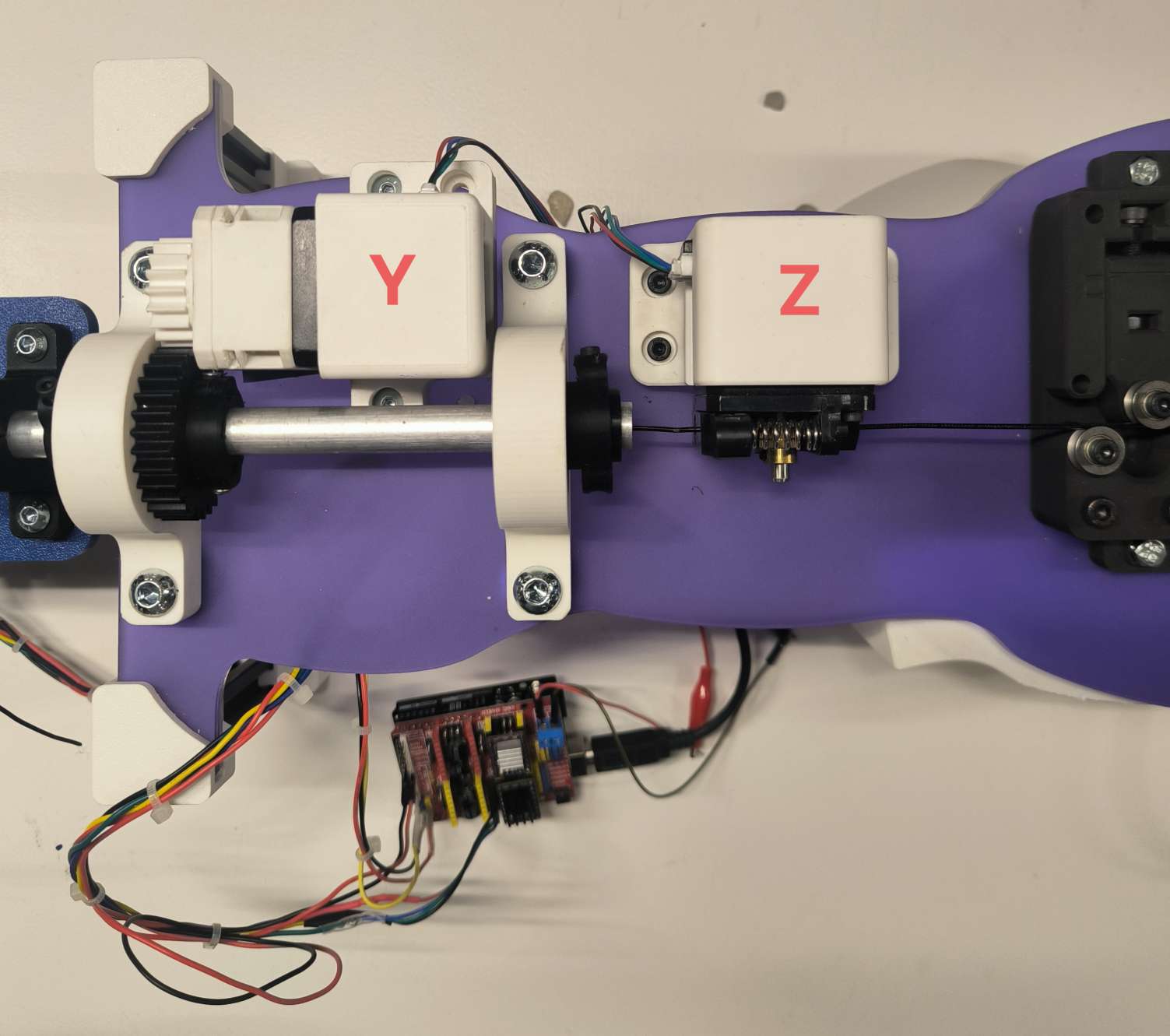
First step was to define the different motors in our design to an X, Y, Z or A from the CNC shield:
- bender motor which bends the wire by a certain angle, X
- z-rotational motor that rotates the bending plate by an angle to bend the wire on the Z axis, Y
- the feeder motor which feeds the wire a given distance, Z
- a small servo motor to control the up and down movement of the copper piece that will do the bending
According to [5] in cpu_map.h verify that line 147 is commented and line 148 is as follows (changes PWN frequency 1kHz for Laser to approximate 50 Hz for servo):
147 // #define SPINDLE_TCCRB_INIT_MASK (1<<CS22) // 1/64 prescaler -> 0.98kHz (J-tech laser)
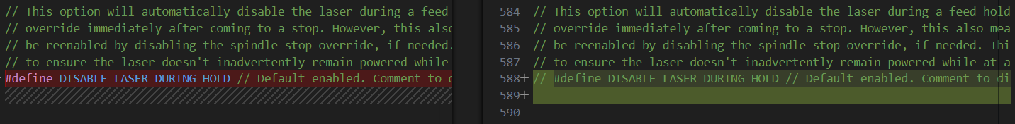
148 #define SPINDLE_TCCRB_INIT_MASK ((1<<CS22)|(1<<CS21)|(1<<CS20)) //1/1024 prescaler -> 61 Hz (for Servo)Also verify that the undesirable PWN power changing is disabled (commented):
587 // #define DISABLE_LASER_DURING_HOLDWhen compiling the GRBL there is a trick to delete all of the temporary files in the arduino folder to ensure that the Arduino IDE is takin the correct config.h and cpu_map.h files and not the old ones. https://github.com/gnea/grbl/wiki/Compiling-Grbl give trouble shooting for this step.
Stepper Motor Driver
We chose to use the DRV8825 motor drivers with the CNC shield. More details can be found on the following page:
For our design we chose to use a microstep resolution offering 1/16 steps = 3200 microsteps.
| Mode 0 | Mode 1 | Mode 2 | Microstep resolultion |
| 0 | 0 | 0 | Full step |
| 1 | 0 | 0 | Half step |
| 0 | 1 | 0 | 1/4 step |
| 1 | 1 | 0 | 1/8 step |
| 0 | 0 | 1 | 1/16 step |
| 1 | 0 | 1 | 1/32 step |
| 0 | 1 | 1 | 1/32 step |
| 1 | 1 | 1 | 1/32 step |
Calibration
The first driver took the most time as we encountered the following problems :
- not enough voltage to turn the motor connected to VMOT pin
- wires coming from the motor are not in correct order for the A1 A2 B1 B2 pins
- reference voltage and limiting current too low
To resolve 1 we simply needed to increase the voltage above 8V.
To resolve 2 we needed to identify the pairs by connecting two of the 4 wires together to see which gave more resistance. Two wires sharing the same loop will create more resistance. One pair is then connected to A1 and A2, and the other B1 and B2.
[5] explains clearly how to calibrate the reference voltage and adjust the potentiometer on the driver until the multimeter receives 0.7-0.9 V between the cathode on the potentiometer itself and the anode connected to ground. Be careful to not touch any of the other components on the driver with the cathode, as it risks to burn the driver.
The current limit for the DRV8825 is given by :
Since Rs is 0.1 ohm, the =
amps
Homing
To initiate the motor, we need to home the positioning: first installing the python serial library;
python3 -m pip install pyserial and understanding the grbl settings:
$H sends the motor to home it’s position using grbl. It will set the point where the end stop is triggered as 0 for the motor. It will home twice, first seeking the home at a faster speed and then refining the home at a slower speed.
If it starts to move in the wrong direction we need to invert the direction using Gcode : $23=1
G92 X0Y0Z0 allows the user to set the origin at the current position.
Bending motor calibration
Here we are going to calibrate the bending motor, X, to rotate the bending platform 1º with the command G0 X1, which would typically move 1.8º.
We initially have 1.8º per step per 200steps. We also have two gears with 18 and 30 teeth, the former being the one coaxial and attached with the motor. Therefore we have a 5/3 gear ratio.
360 / (200*5/3)= 360º/333.3 = 1.08º per step of the end gear.
$100, $101 and $102 set the steps/mm for the X, Y and Z motors respectively. We need to modify this so it is steps/º. Not only that we need to consider that we are using a 1/16 microstepping.
for the X bending motor, $100 needs to be set to
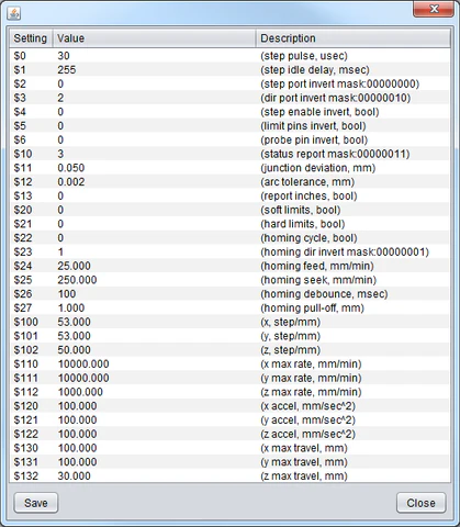
These are the default values for the Arduino board and CNC shield, retrieved by entering ‘$$’ in the serial monitor.
$0=10
$1=25
$2=0
$3=0
$4=0
$5=0
$6=0
$10=1
$11=0.010
$12=0.002
$13=0
$20=0
$21=0
$22=0
$23=0
$24=25.000
$25=500.000
$26=250
$27=1.000
$30=1000
$31=0
$32=0
$100=250.000
$101=250.000
$102=250.000
$110=500.000
$111=500.000
$112=500.000
$120=10.000
$121=10.000
$122=10.000
$130=200.000
$131=200.000
$132=200.000
These are the values we change for the Bender
$4=180
$10=2
$22=1
$23=1
$24=500
$100=14.815
$110=5000
$120=100
We start by homing X and then move on to calibrate the Feeder, Y in the same manner as it has a similar gear ratio.
We then move on to calibrate the feeder, Z. The feeder pulls the wire through the motor at a given feed rate in mm/min. $102 is the number of steps the Y-axis motors needs to move to travel 1 mm. By trial and error we determine $102 = 95
$1 = 180 allows the motors to remain enabled with full power even when not solicited (range between 0-255) to maintain position and hold the wire position.
Calibration of Servo Motor
The following is inspired from the following drawing bot [5].
For the servo, as mentioned previously, we hack the stepper motor GRBL code by modifying the config.h and cpumap.h, adding the following lines of code :
cpu_map.h : comment line 147 and add line 148
147    // #define SPINDLE_TCCRB_INIT_MASK      (1<<CS22)               // 1/64 prescaler -> 0.98kHz (J-tech laser)
148    #define SPINDLE_TCCRB_INIT_MASK ((1<<CS22)|(1<<CS21)|(1<<CS20))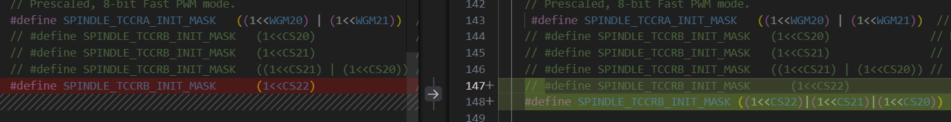
The following commands are used to control the servo motor so that the bending pipe is either down or up:
M03 S120    // down position for skip
M03 S50     // up position for bend
Using the Z+ endstop pin to control the servo. The servo to copper bar mechanism can be a little temperamental, so these S values have to be changed from time to time using intuition, as they cannot be zeroed with G92.
Optimised Stepper motor settings:
The GRBL setup for the motors is as follows:
 $1=180
 $2=0
 $3=0
 $4=0
 $5=0
 $6=0
 $10=2
 $11=0.010
 $12=0.002
 $13=0
 $20=0
 $21=0
 $22=1
 $23=1
 $24=500.000
 $25=500.000
 $26=250
 $27=1.000
 $30=1000
 $31=0
 $32=0
 $100=14.815
 $101=14.815
 $102=95.000
 $110=5000.000
 $111=250.000
 $112=250.000
 $120=100.000
 $121=20.000
 $122=20.000
 $130=200.000
 $131=200.000
 $132=200.000
Improving the Y axis rotation
We noticed that the gears on the motor would slip under the weight of the rotating platform hosting the X motor at angles above 26º. In order to prevent this we decided to look for a suitable gear reduction design to the Y NEMA17 motor. We found the following design :
https://www.printables.com/model/281222-nema17-planetary-gearbox/files
We took the following .stl file. modified it to our design and uploaded the different reducer parts into chitabox for print. The first print with the resin printer did not turn out correctly as I did not separate all of the parts correctly.
We reprinted with the Bamboo X1 Carbon printer in PLA to save time.
The reducer has allowed us to hold the position past 90º which is fantastic.
G-ing the code
We’ve reached the point were we want to feed the machine a predefined set of instructions in .gcode format. Let’s start with a very simple shape.
; Remember to run the inizialitation sequence

; --- Side 1 ---
G1 Z50 F1000       ; Feed 50mm of wire

G1 X87 F500        ; Close the gap (~90 degrees). We should calibrate the aprox dist.
G1 X177 F500       ; Bend 90 degrees more (87 + 90 = 177 total)

; --- Side 2 ---

G1 X0 F500           ; Bring machine home
G1 Z50 F1000       ; Feed next side
G1 X87 F500        ;
G1 X177 F500       ;

; --- Side 3 ---
G1 X0 F500           ;
G1 Z50 F1000       ;
G1 X87 F500        ;
G1 X177 F500       ;

; --- Side 4 ---
G1 X0 F500           ;
G1 Z50 F1000       ;
G1 X87 F500        ;
G1 X177 F500       ;

M5 ; (Optional) stop any spindles or motors
M30 ; End of program
Now let’s try to do the Eiffel Tower or a BAUHAUS chandelier.
Main Script
The main script has two main components: 1) the machine control loop (including Main menu and GCODE processing) 2) the svg to gcode code
import serial
import time
import os
from svgpathtools import svg2paths
from math import atan2, degrees, sqrt

# --- Serial & G-code File Config ---
serial_port = "COM9"  # Replace with your serial port
baud_rate = 115200     # Default baud rate for Grbl
timeout = 1            # Timeout in seconds

# Define the G-code file name (must be in same folder as this script)
gcode_file_name = "square_bend.gcode"

# --- Predefined Initialization Commands ---
initialization_commands = [
    "G21",  # Set units to millimeters
    "G90",  # Set to absolute positioning
    "$H",   # Home all axes
    "G92 X0Y0Z0",  # Set current position as origin
]

# --- Helper: Send G-code to Grbl ---
def send_gcode(grbl, gcode):
    grbl.write((gcode.strip() + "\n").encode())
    time.sleep(0.1)  # Adjust delay if necessary
    response = []
    while grbl.in_waiting > 0:
        line = grbl.readline().decode().strip()
        response.append(line)
    return response

# --- Run G-code File ---
def run_gcode_file(grbl, file_path):
    if not os.path.isfile(file_path):
        print(f"File not found: {file_path}")
        return

    with open(file_path, 'r') as f:
        lines = f.readlines()

    print(f"Sending G-code from {file_path}...")
    for line in lines:
        stripped = line.strip()
        if stripped == "" or stripped.startswith(";"):
            continue  # Skip empty lines and comments
        print(f"> {stripped}")
        response = send_gcode(grbl, stripped)
        for resp in response:
            print(resp)
    print("Finished running file.")

# --- SVG to Bending Instructions Converter ---

# Gcode generation variables
gap_angle_left = 92
gap_angle_right = -65

# Helper functions for SVG processing
def calculate_distance(p1, p2):
    return sqrt((p2[0] - p1[0])**2 + (p2[1] - p1[1])**2)

def calculate_angle(p1, p2):
    return degrees(atan2(p2[1] - p1[1], p2[0] - p1[0]))

def normalize_angle(angle):
    while angle > 180:
        angle -= 360
    while angle < -180:
        angle += 360
    return angle

from math import atan2, degrees, pi

def angle_between_segments(p1, p2, p3):
    # Vector A (from p1 to p2)
    ax, ay = p2[0] - p1[0], p2[1] - p1[1]
    # Vector B (from p2 to p3)
    bx, by = p3[0] - p2[0], p3[1] - p2[1]

    # Angle of each vector
    angle1 = atan2(ay, ax)
    angle2 = atan2(by, bx)

    # Difference in angles
    delta = degrees(angle2 - angle1)

    # Normalize between -180 and 180
    while delta <= -180:
        delta += 360
    while delta > 180:
        delta -= 360

    return delta


def extract_points_from_svg(svg_file):
    """
    Extract key vertices from all SVG paths.
    Returns a list of (x, y) points where the wire should bend.
    """
    paths, _ = svg2paths(svg_file)
    points = []

    for path in paths:
        for segment in path:
            start = (segment.start.real, segment.start.imag)
            end = (segment.end.real, segment.end.imag)
            # Add the starting point if it's the beginning of the path or different from last point
            if not points or points[-1] != start:
                points.append(start)
            # Add the end point if different
            if points[-1] != end:
                points.append(end)
    return points

def compute_instructions_absolute(points, angle_threshold=1):
    instructions = []
    if len(points) < 2:
        return instructions
    instructions.append(f"M3 S50")
    i = 0
    while i < len(points) - 1:
        start = points[i]
        next_point = points[i + 1]
        segment_length = calculate_distance(start, next_point)
        last_angle = calculate_angle(start, next_point)

        j = i + 1
        while j + 1 < len(points):
            angle = calculate_angle(points[j], points[j + 1])
            if abs(normalize_angle(angle - last_angle)) > angle_threshold:
                break
            segment_length += calculate_distance(points[j], points[j + 1])
            j += 1

        instructions.append(f"G0 Y{round(segment_length)}")
        instructions.append(f"G92 Y0")


        if j + 1 < len(points):
            # p1 = last point of the previous straight run
            # p2 = the actual corner / bend point
            # p3 = the first point of the next run
            p1 = points[j - 1]
            p2 = points[j]
            p3 = points[j + 1]

            bend = angle_between_segments(p1, p2, p3)
            abs_bend = normalize_angle(bend)
            if(abs_bend >= 0):
                angle_gap = abs_bend + gap_angle_left
                instructions.append(f"G0 X{round(angle_gap)}")
                instructions.append(f"G0 X0")
                instructions.append(f"")
            else:
                instructions.append(f"M3 S110")
                instructions.append(f"G0 X{round(180)}")
                instructions.append(f"M3 S50")
                print(f"Angle: {abs_bend + gap_angle_right}")
                angle_gap = 180 + abs_bend + gap_angle_right
                instructions.append(f"G0 X{round(angle_gap)}")
                instructions.append(f"M3 S110")
                instructions.append(f"G0 X0")
                instructions.append(f"M3 S50")
                instructions.append(f"")


        i = j

    return instructions

def export_instructions(instructions, output_file="shape.gcode"):
    with open(output_file, 'w') as f:
        f.write("; Custom wire bending instructions\n")
        for instr in instructions:
            f.write(instr + "\n")

def svg_to_instructions(svg_path, output_path="shape.gcode"):
    print(f"Parsing SVG: {svg_path}")
    points = extract_points_from_svg(svg_path)
    if len(points) < 2:
        print("Not enough points extracted.")
        return
    print(f"Extracted {len(points)} points.")
    instructions = compute_instructions_absolute(points)
    export_instructions(instructions, output_path)
    print(f"Instructions written to {output_path}")

# --- Main Menu ---
try:
    # Open the serial port to the Grbl board
    with serial.Serial(serial_port, baud_rate, timeout=timeout) as grbl:
        print(f"Connected to {serial_port} at {baud_rate} baud.")
        grbl.write(b"\r\n\r\n")
        time.sleep(2)
        grbl.flushInput()

        while True:
            print("\nMenu:")
            print("1. Enter G-code manually")
            print("2. Run initialization sequence")
            print("3. Run G-code file")
            print("4. SVG to G-code")
            print("5. Exit")
            choice = input("Select an option: ")

            if choice == "1":
                while True:
                    gcode = input("Enter G-code (or type 'back'): ")
                    if gcode.lower() == "back":
                        break
                    response = send_gcode(grbl, gcode)
                    for line in response:
                        print(line)

            elif choice == "2":
                print("Running initialization sequence...")
                for cmd in initialization_commands:
                    print(f"Sending: {cmd}")
                    response = send_gcode(grbl, cmd)
                    for line in response:
                        print(line)
                print("Initialization complete.")

            elif choice == "3":
                gcode_file_name = input("Enter SVG file name: ")
                script_dir = os.path.dirname(os.path.abspath(__file__))
                gcode_file_path = os.path.join(script_dir, gcode_file_name)
                run_gcode_file(grbl, gcode_file_path)

            elif choice == "4":
                svg_name = input("Enter SVG file name: ") #Make sure it is in the same folder
                if not svg_name.lower().endswith(".svg"):
                    svg_name += ".svg"
                script_dir = os.path.dirname(os.path.abspath(__file__))
                svg_path = os.path.join(script_dir, svg_name)
                svg_to_instructions(svg_path)

            elif choice == "5":
                print("Exiting...")
                break

            else:
                print("Invalid option. Please try again.")

except serial.SerialException as e:
    print(f"Error: {e}")
except KeyboardInterrupt:
    print("\nScript interrupted by user.")
06— Making the Machine: Physical Construction
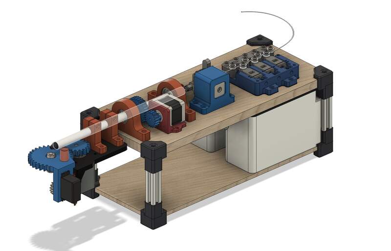
About the Mechanical CAD
The mechanical design is a heavily modified version of the original design with a number of additions. Several pieces like the straightening assembly and the planetary gear reduction were adapted from pre-existing designs (straightener and planetary gear reducer). Additionally, the extrusion mechanism is produced by Creality and can be sourced here. All fasteners are common metric machine screws and bolts. These fasteners can be sourced at your local hardware store. The aluminum pipe may be tricky to source as it was just scrap laying around the lab. Fits have been adjusted for a well calibrated 3D printer (we used a Bambu Carbon X1).
Two important notes
- Do not print counterweights (they have known design issues and are not needed).
- The layered acrylic is fragile so be careful mounting the press fit corner brackets.
Project Files
Below is the included final Assembly CAD file to reproduce the project. Components types are clearly labelled in the assembly file names. The .step assembly (with labeled components) are provided for the mechanical assembly and a KiCAD file is provided for the milled PCB.