06— Electronics Design
Assignment
- Group assignment:
- Use the test equipment in your lab to observe the operation of a microcontroller circuit board (as a minimum, you should demonstrate the use of a multimeter and oscilloscope)
- Document your work on the group work page and reflect what you learned on your individual page
- Individual assignment:
- Use an EDA tool to design a development board to interact and communicate with an embedded microcontroller
00— Reflection
In this week we learned to use the Oscilloscope and multimeter as a group. With both its clear that these are very versatile tools and a lot more could be learned to use these to diagnose and trouble shoot circuit or general electrical issues.
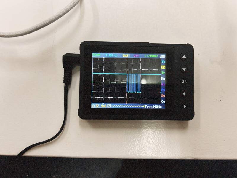
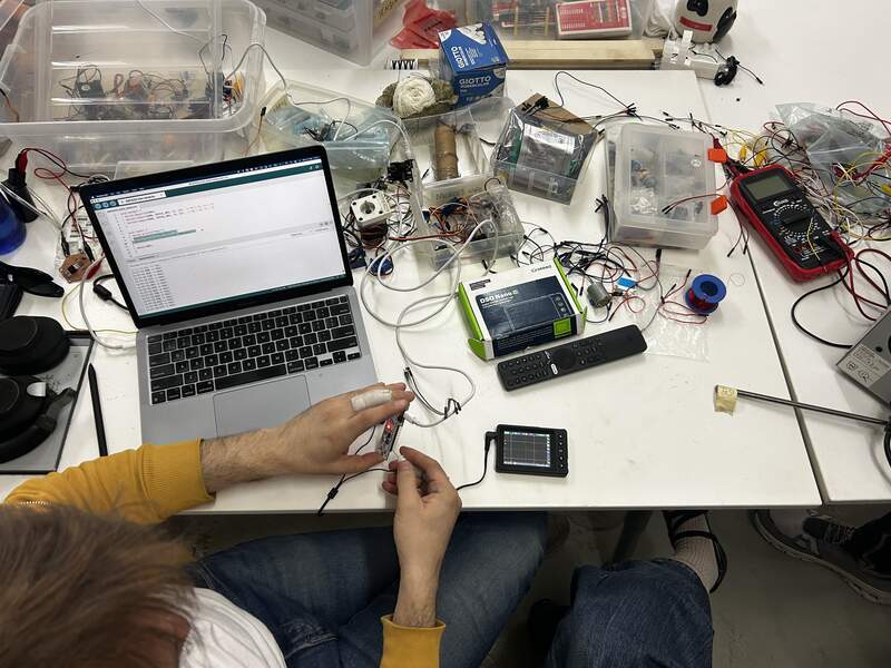
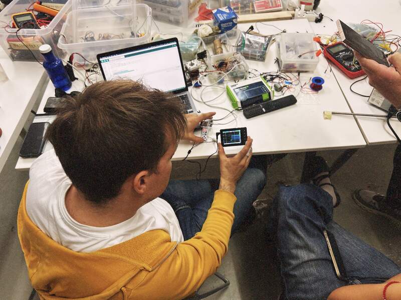
01—Using an Oscilloscope
Here we used an Oscilloscope to sample serial communication on the Barduino. This was from a tutorial that Dani did in class. We subsequently went over this process several times. Here we were using the Oscilloscope to view a pin sending serial communication. Interestingly we were able to observe that the longer the serial message the more numerous the pulses were. In the week after we used the Oscilloscope extensively to confirm correct functioning of the stepper motor drivers for our CNC Wire bender we developed for machine week.
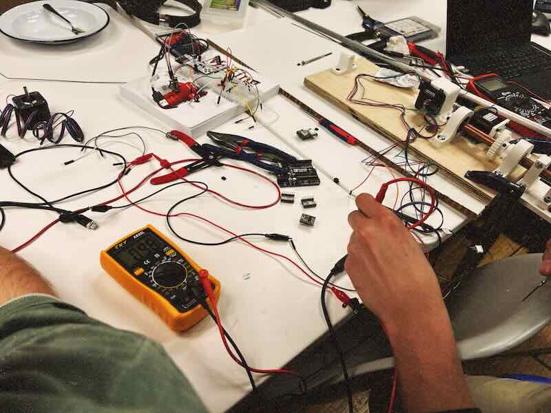
02—Using a Multimeter
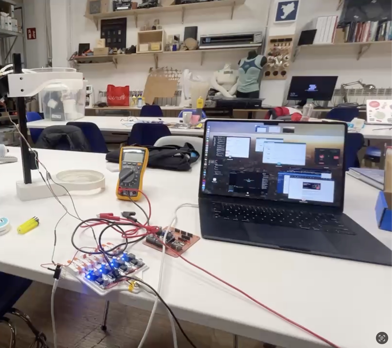
Measuring incoming voltage to Xiao and setting voltage of buck converters.
This was a project that Andrew was setting up for his final project. To start the continuity function on the meter was used to check for shorts on the original milled board. The 4x buck converters pictured are used as a way of sending out individual voltages to test different output devices. To configure the voltages each buck converter needs to have a small trimmer potentiometer adjusted with a multimeter hooked up to its output that is set up to measure Voltage DC. This allows you to observe the output voltage as you adjust to the target voltage. Additionally, once the whole test rig was set up it was confirmed that the Xiao was receiving adequate voltage to power it (+5V).
Measuring Stepper motor driver voltage to calculate adjustable motor current setting
Using the multimeter to measure the voltage at the output of current limiting SMD potentiometer on a stepper motor driver. Below we have set the multimeter to measure (meter dial set to read DC voltage).