07— Computer Controlled Machining
Assignment
- Group assignment:
- Complete your lab's safety training
- Test runout, alignment, fixturing, speeds, feeds, materials and toolpaths for your machine
- Document your work to the group work page and reflect on your individual page what you learned
01 — Safety Considerations
(From memory) Here’s a summarized list of all safety considerations:
No loose accessories Ex: necklace, scarf, kimono belt etc.
Long-hair should be tied.
Only one person should operate the machine (prevent fi activating the machine while someone is changing the drill tip).
Always wear glasses inside the wood workshop, especially with an active cnc machine.
Do not use your hands as tools nor try to reach machines that are active
In case of danger, use the emergency stop button that all machines have
02 — Runout, alignment, fixturing, speeds, feeds and tool paths test
We tested different clearance rates by cutting U-shaped pieces provided by our instructor Josep. We produced 4 different pieces which had an varying gap width between the pieces arms. This width ranged from -0.40 to +0.20 mm (quite not sure about this number).
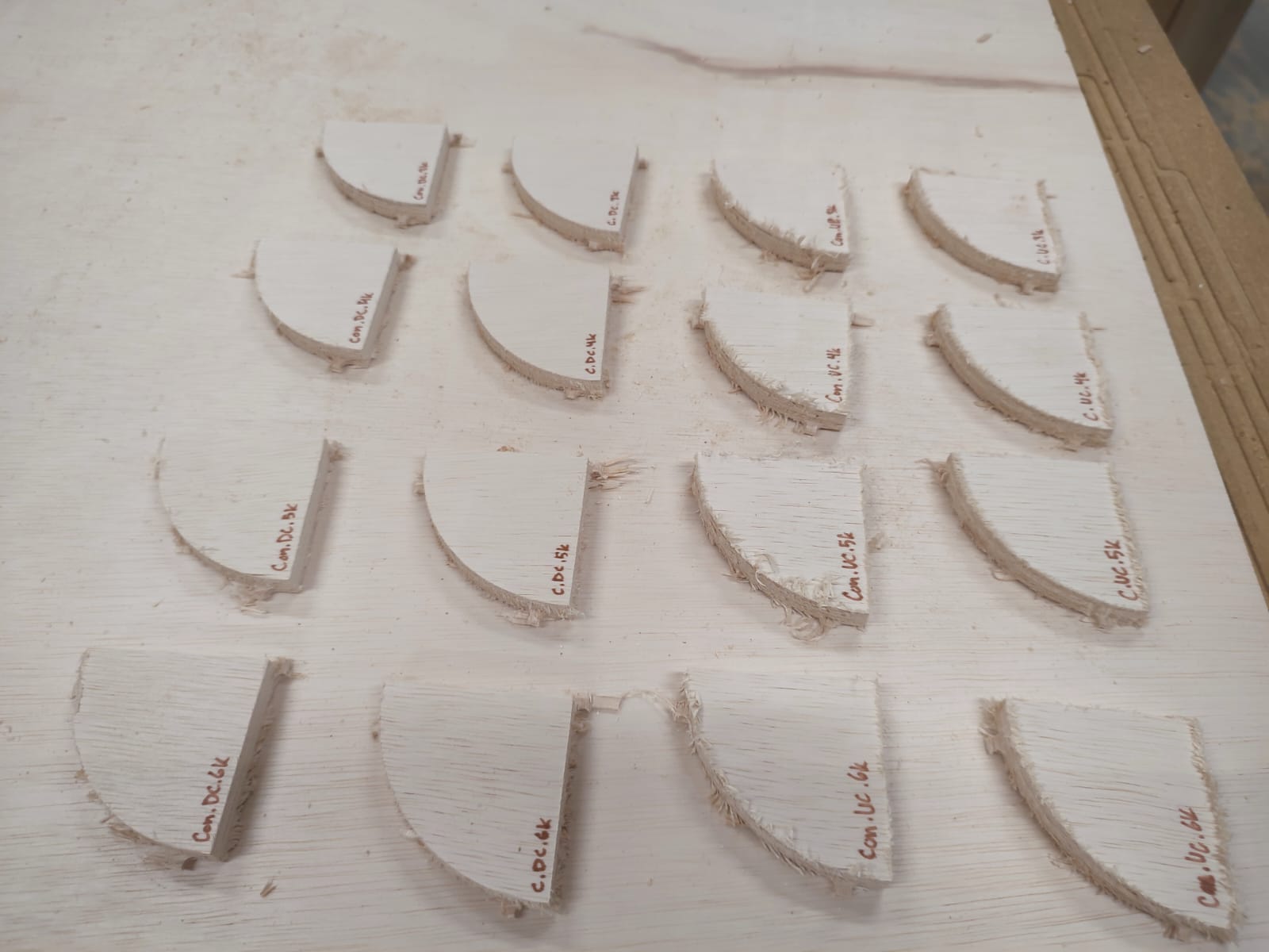
We tested different combinations of cut direction (downcut/upcut), milling (conventional/climb) and different feed rates (from 3 to 6k mm/min). We did this by cutting a quadrant-like shape several times, applying different settings each time. This resulted in a total of 32 pieces. We later used these pieces to find our preferred settings on our individual assignments’ cuts.
03 — Machine setup
Our instructors Josep and Dani guided us through the setup process. Here’s a summary of the quadrant-piece cuts:
- We collected our test plywood board and set it up in the machine, making sure it is aligned with and fully inside the sacrificial layer.
- We zeroed the cnc by bringing it to the corner of the board.
- We uploaded the screw placement file and milled the screw holes.
- We fixed the plywood board to the sacrificial layer by adding a screw in each hole.
- We re-calculated the zero for the z-axis, since the height of the board could have changed once secured.
- We then uploaded the toolpath file for the downcut pieces and proceeded to make the cuts.
- After the cuts, we changed the tool tip to an upcut one.
- We then uploaded the toolpath file for the upcut pieces and proceeded to make the final cut.
- The last step was then removing the screws and sanding the bridges between the pieces and the main layer. We should also fight back our adhdness and store the final pieces somewhere.
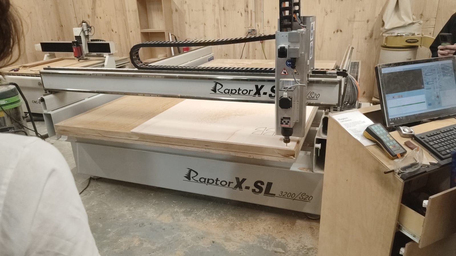
Board set and screwn. Preparing the UC files after finishing the DC-piece cut
04 — Materials test & Planning
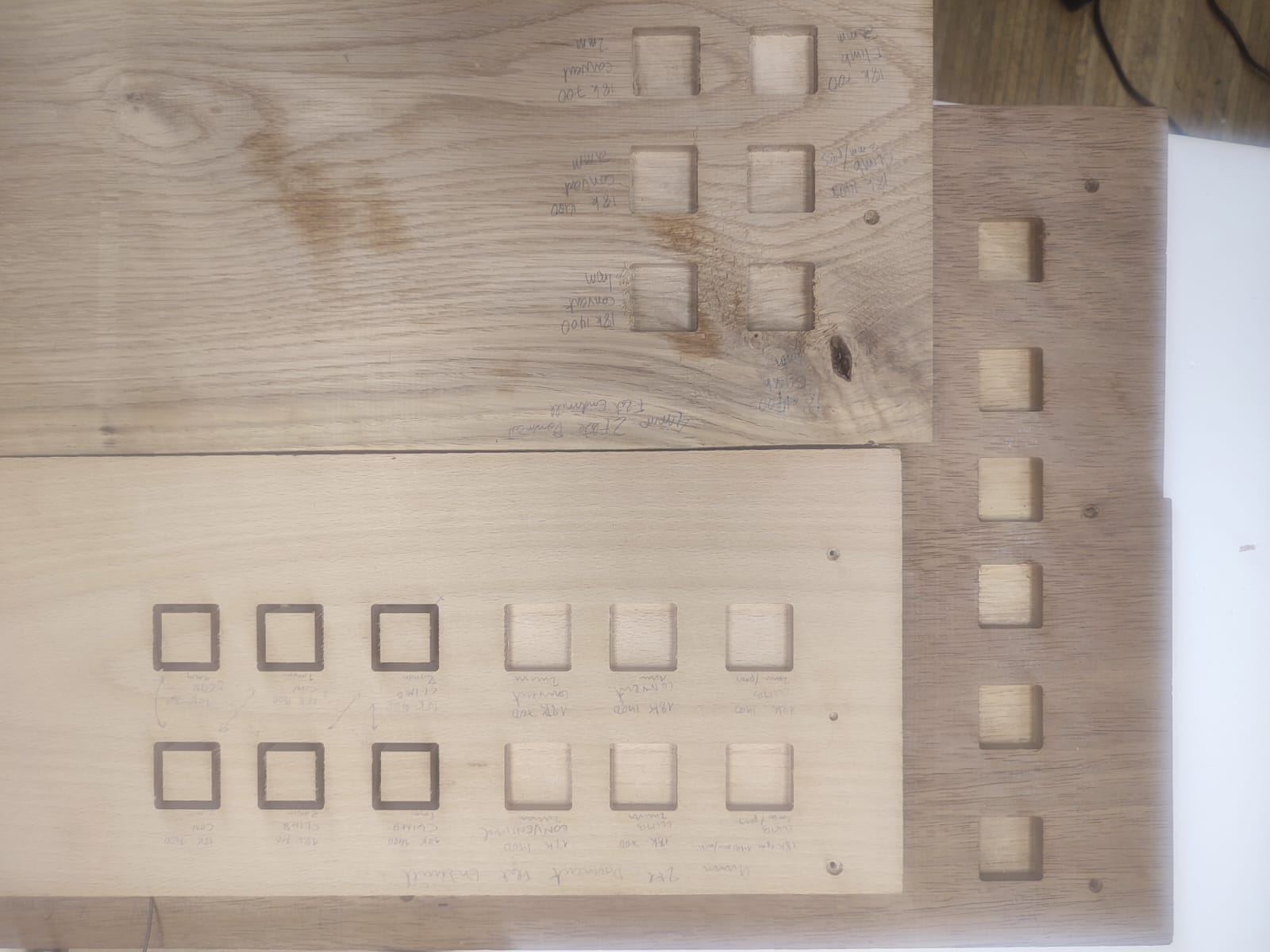
We were just missing one thing from the previous tests: trying out different materials! Nonetheless, Mark and Gonzalo got some Beech, Oak and Iroko samples for their projects, which were perfect for the task.
We knew that there could are potential issues to be aware of. There is always something new that rears its ugly head. Here are some issues and fixes:
a)
Burning: Feed rate is likely too slow / RPM too high/ Using a dull tool, or the tool is rubbing instead of cutting.
The Fix: Increase feed rate (i.e. 500-700mm/min), Lower RPM slightly, Use newer or sharper tool, Clean tool if resin builds.
How to deal with it on the fly: In CAM tool settings change RPM and feed rate.
b)
Chatter/Vibration: Means pushing bit too deep or fast or RPM too slow.
The Fix: Reduce depth per pass (e.g. 2mm to 1mm), lower feed rate (e.g.700 mm/min to 500mm per min), Increase RPM (e.g. 12000-16000RPM), Check tool tightness in the collet.
How to deal with it on the fly: Adjust depth per pass in CAM under “Passes” OR us ehigher RPM from controller or in tool setup.
c)
If cuts are dusty ,not chips: Means rubbing not cutting/ Chip load too small.
The Fix: Increase feed rate (so each flute cuts a thicker chip), Reduce RPM (to avoid too many tiny cuts), User fewer flutes (2 flutes). N.b. Chip load = feed rate / (rpm x # flutes)- (aim for 16000 Rpm speed and chip load of approximately 0.5 - 0.15mm.
Rhino CAM
We need to input settings in a software to generate a Gcode for the CNC mill. In our case we use Rhino CAM which is a plugin found in Rhino. The Gcode tells the CNC mill where and when to move on the X,Y and Z axes. First we arrange the pieces in a nested format in Rhinocam according to specific sizes of each of the pieces of the wood. We do this for both the engraving to put in screws and then the pocket cuts and profile cuts. We put in dogbones so the cuts in the inside corners will come out properly. The next step is using the software to input a feed rate, spindle speed, # of flutes, cut depths.
05 — Results shots
.jpeg)