08—Electronics Production
Assignment
- Group assignment:
- Characterize the design rules for your in-house PCB production process: document feeds, speeds, plunge rate, depth of cut (traces and outline) and tooling.
- Document the workflow for sending a PCB to a board house
- Document your work to the group work page and reflect on your individual page what you learned
00—Reflection
Below we have documented the process of characterizing the PCB milling process. We have tried to document all steps that are relevant to the process of milling a PCB. Ultimately this assignment was done after the fact so it serves as more of a post mortem of best approaches as practically all conceivable mistakes have been made by at least one of us when learning how to get good result in the PCB milling process.
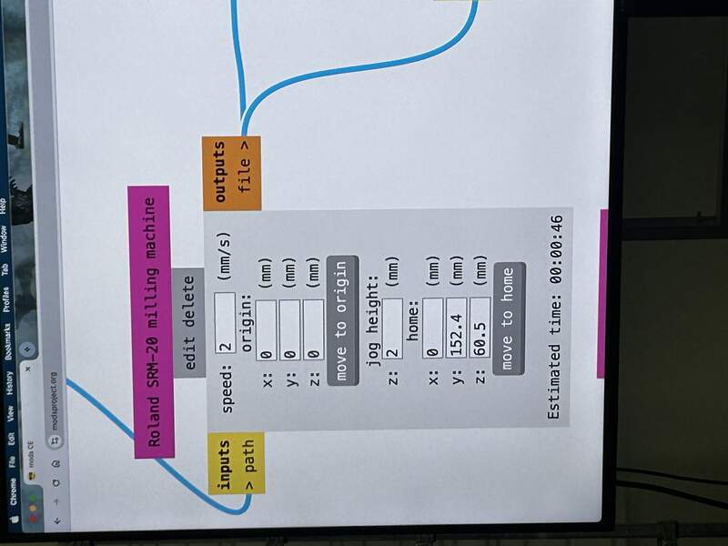
01— In House Board production on the Rolland SRM-20 Mill
About section: below is a detail of how to set up the Rolland SRM-20 once you have your files prepped and on the computer in the format the SRM-20 mill takes.
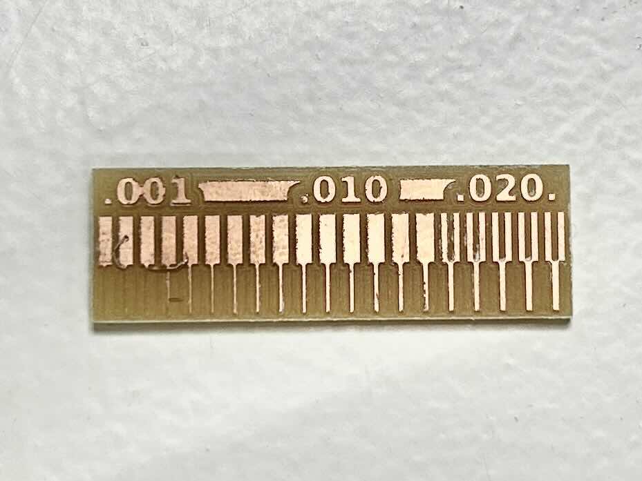
Characterization Test— Prep

Settings used in Mods were the following
max depth→ 1.75 to preserve the base plate
speedtraces 3 mm/s; holes 1.5 mm/s; cut 0.5 mm/s
jog height5mm to be cautious
Characterization Test— Results
- Minimum trace width: For the lower trace section we notice traces tend to come out best at
.4mmwidth.
- Minimum clearance width: for the upper trace section we noticed that .
4mmseparation between traces was the best value for quality.
Mods setup
- Open Mods website (works better in Safari and Firefox in my experience)
RMC → programs → open program → SR-20… Mill 2D PCB
- Bring your Traces PNG into the
Read PNG block
LMC → traces preseton Set PCB Defaults- For the holes and profile layers choose
LMC → mill outline preset
- For the holes and profile layers choose
Cut DepthandMax Depthset to .15mm on the Mill Raster 2D block- For the holes and profile layers this setting does not need to be changed from default
- For the holes and profile layers this setting does not need to be changed from default
- On the Roland SRM Milling Machine… block edit the following:
Passes[2] X[0] Y[0] Z[0]
- For the input output Roland SRM Milling Machine… there is a slider button in the off state as default, change to
On/Off [ON]
- This automatically downloads the machining file to your computer.
- Rename the files and place in a folder to be brought over to the Mill!
Mill Setup
- Prep: Retrieve your copper plate unless you are doing a double sided board you need to grab single side FR-1 copper board. Clean the sacrificial board with a paint brush so that the mounted copper plate will lay flat.
- Mount: Apply double sided adhesive tape to the back of the PCB stock. Make sure the adhesive tape extends past the board and fold it over. This ensures that the adhesive does not fold over on itself and raise the height of the PCB stock. Similarly, the adhesive needs to be pressed on evenly so that it does not add extra height to the copper board stock. Mount your copper stock to the bed. The stock needs to be mounted flat to the bed. Ensure it is totally flat by making sure you have applied even pressure to every part of the board for consistent adhesion.
- Add in your end mill: Put your 1/64” bit into the collet and tighten the set screw finger tight so it is secure (do not over tighten).
- Set you XY: Move the spindle Set your XY origin in the SRM software.
- Set your Z: Carefully position you Z position in the center of your copper stock the bit should be slightly above the stock and not touching. Loosen collet and carefully move bit downward using SRM control software until it is both touching the stock and the shank is mostly in the collet for maximum stability when milling. Tighten the bit. Set your z origin.
- Load your file: Click the
cutbutton clear any files in the dialog. Load in your “traces” machining file you prepared earlier.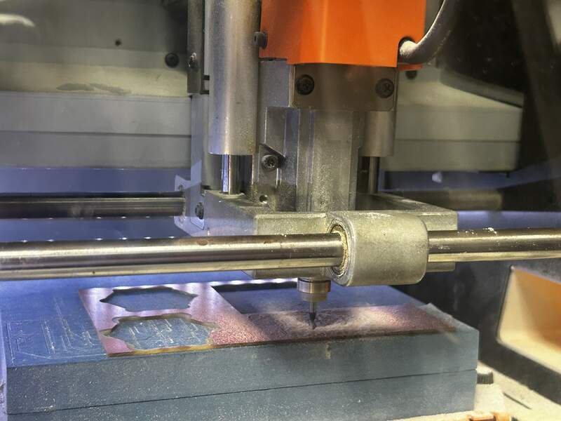
- Start your machine: Click
Outputthis will start your machine.
- Repeat the Z origin set process detailed earlier to with the 1/32” bit. Load in the file using steps detailed earlier and begin cutting your “holes”.
- Repeat process for cutting your “edge cuts” file.
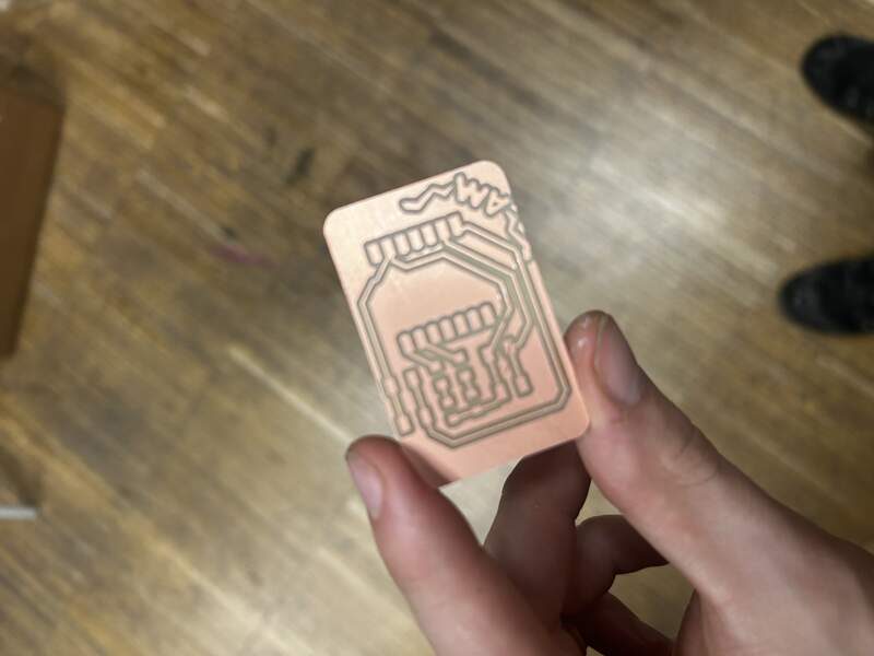
- Below is an example of a simple 1 sided board with no holes.
02— JLCPCB Order Specifications
- Export your Gerber file from KiCAD
- Go to JLCPCB website and upload your Gerber file

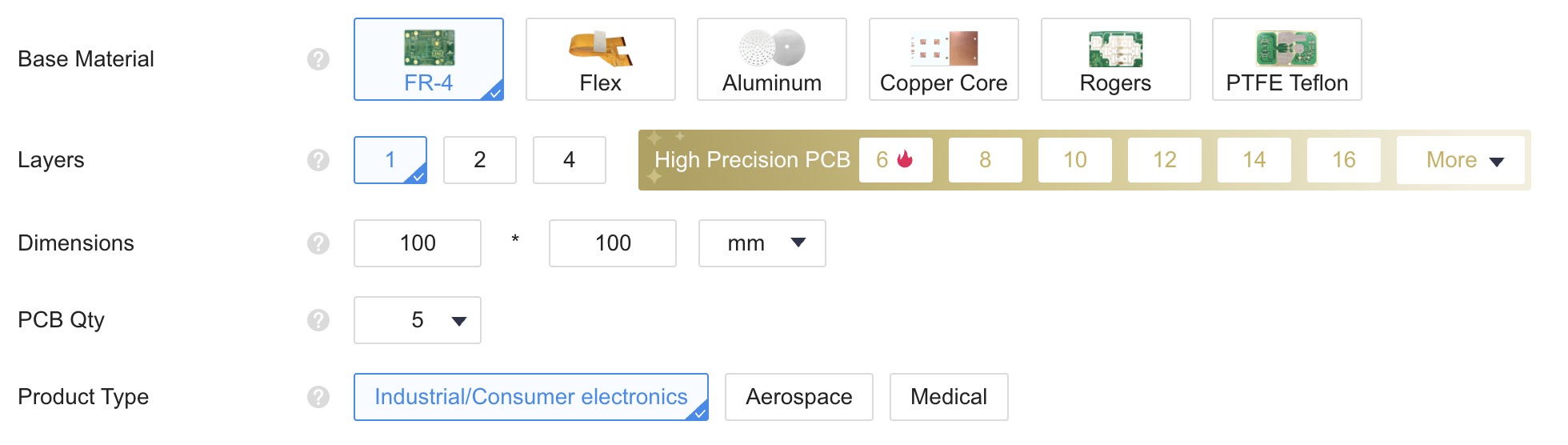
- Fill out primary manufacturing details shown below
- Base Material: FR-4 is the standard choice other options are more specialty.
- Layers: In our case we are using only 1 layer, but there is minimal price difference for 2 and 4 layers
- PCB Qty: 5 is minimum order quantity
- Dimensions: auto update once you upload the Gerber file
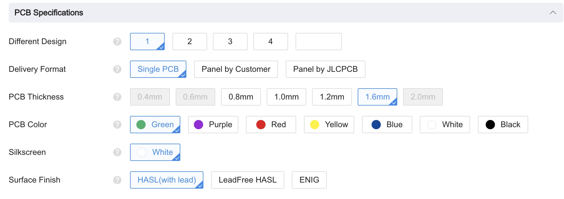
- For PCB Specifications
- Fill out in the following way. All of the default here are appropriate.
- Fill out in the following way. All of the default here are appropriate.
- If you don’t know what these are you don’t need them ;). These settings are for more specialty PCBs.

- Now you just gotta pay for it and wait a week to get it in the mail.