09—Input Devices
Assignment
- Group assignment:
- Probe an input device(s)'s analog levels and digital signals
- Document your work on the group work page and reflect on your individual page what you learned
00—The Encoder
For our group project we used the DFR Rotory Encoder Module. This is a very robust well designed encoder module that works over I2C. It is simultaneously also technically an output device as it has LEDs that can actively display its position.
Below is its pinout
| Num | Label | Description |
| 1 | VCC/+ | Power+ |
| 2 | GND/- | Power- |
| 3 | SCL/C | I2C Clock line |
| 4 | SDA/D | I2C Data line |
DIP switches on the back allow for the I2C channel to be configured
| 1 | 2 | ADDR |
| 0 | 0 | 0x54 |
| 0 | 1 | 0x55 |
| 1 | 0 | 0x56 |
| 1 | 1 | 0x57 |
01— Flashing the Example Code
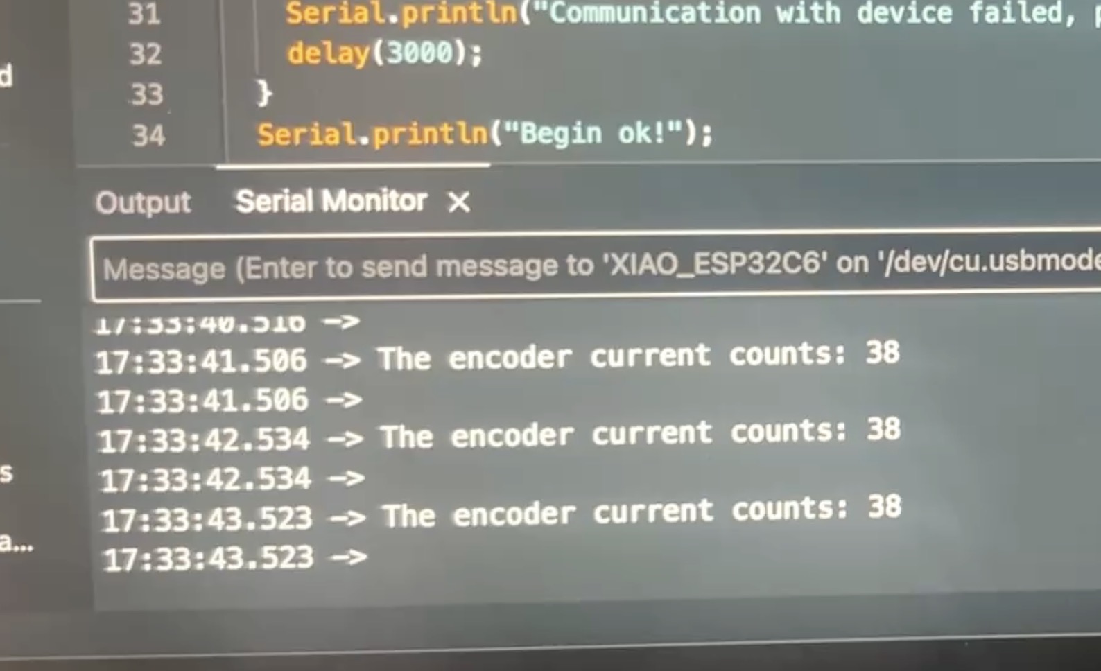
The below will represent the current state of the encoder through the LEDs along its edge. In addition it will also send serial through the USB serial port. This is very convenient to get this group project out of the way quickly as it is being completed several weeks after it was due.
/*!
 * @file        getData.ino
 * @brief       This demo shows how to get basic encoder information, the current count and rotation gain
 * @copyright   Copyright (c) 2010 DFRobot Co.Ltd (http://www.dfrobot.com)
 * @license     The MIT License (MIT)
 * @author      [qsjhyy](yihuan.huang@dfrobot.com)
 * @version     V1.0
 * @date        2021-09-15
 * @url         https://github.com/DFRobot/DFRobot_VisualRotaryEncoder
 */
#include <DFRobot_VisualRotaryEncoder.h>

/**
 * Instantiate an object to drive our sensor;
 * Set address according to encoder DIP switch CH1 and CH2:
 * | 1 | 2 | ADDR |
 * |---|---|------|
 * | 0 | 0 | 0x54 |
 * | 0 | 1 | 0x55 |
 * | 1 | 0 | 0x56 |
 * | 1 | 1 | 0x57 |
 */
DFRobot_VisualRotaryEncoder_I2C sensor(/*i2cAddr = */0x54, /*i2cBus = */&Wire);

void setup()
{
  Serial.begin(115200);

  // initialize sensor
  while( NO_ERR != sensor.begin() ){
    Serial.println("Communication with device failed, please check connection");
    delay(3000);
  }
  Serial.println("Begin ok!");

  /**
   * Retrieve basic information from the sensor and buffer it into basicInfo, the structure that stores information
   * Members of basicInfo structure: PID, VID, version, i2cAddr
   */
  sensor.refreshBasicInfo();

  /* Module PID, default value 0x01F6 (the highest two of the 16-bits data are used to judge SKU type: 00: SEN, 01: DFR, 10: TEL; The next 14 numbers are used as num)(SEN0502) */
  Serial.print("PID: 0x0");
  Serial.println(sensor.basicInfo.PID, HEX);

  /* Module VID, default value 0x3343(for manufacturer DFRobot) */
  Serial.print("VID: 0x");
  Serial.println(sensor.basicInfo.VID, HEX);

  /* Firmware version number: 0x0100 represents V0.1.0.0 */
  Serial.print("versions: 0x0");
  Serial.println(sensor.basicInfo.version, HEX);

  /* Module communication address, default value 0x54, module device address (0x54~0x57) */
  Serial.print("communication address:  0x");
  Serial.println(sensor.basicInfo.i2cAddr, HEX);

  /**
   * Get the encoder current gain factor, and the numerical accuracy for turning one step
   * Accuracy range:1~51,the minimum is 1 (light up one LED about every 2.5 turns), the maximum is 51 (light up one LED every one step rotation)
   * Return value range: 1-51
   */
  uint8_t gainCoefficient = sensor.getGainCoefficient();
  Serial.print("Encoder current gain coefficient: ");
  Serial.println(gainCoefficient);

  Serial.println();
  delay(1000);
}

void loop()
{
  /**
   * Get the encoder current count
   * Return value range: 0-1023
   */
  uint16_t encoderValue = sensor.getEncoderValue();
  Serial.print("The encoder current counts: ");
  Serial.println(encoderValue);

  Serial.println();
  delay(1000);
}
In action Serial
In action LEDs light
02— Taking Physical Measurements
Using Oscilloscope to monitor SCL (Serial Clock Line)
- Below is the oscilloscope set to normal trigger mode to view the Serial clock line
- The exact settings are below taken from the prompt “what setting would I use on ocilloscope to view and SDL line?” through chat GPT
Probe Mode 10x (if your probe supports it) Reduces loading and improves signal clarity Channel Connect CH1 to SDA, ground to GND Use CH2 for SCL if you want both lines Voltage Scale 1–2 V/div (for 3.3V or 5V logic) Adjust so signal fits screen vertically Timebase 10 µs/div to start Zoom in/out as needed to resolve individual bits Trigger Mode Edge Trigger, on rising edge Use SCL or SDA as source (whichever looks cleaner) Trigger Level Set at ~1.5V (midway of logic level) Ensures trigger on clean edge 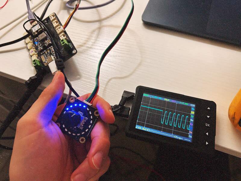
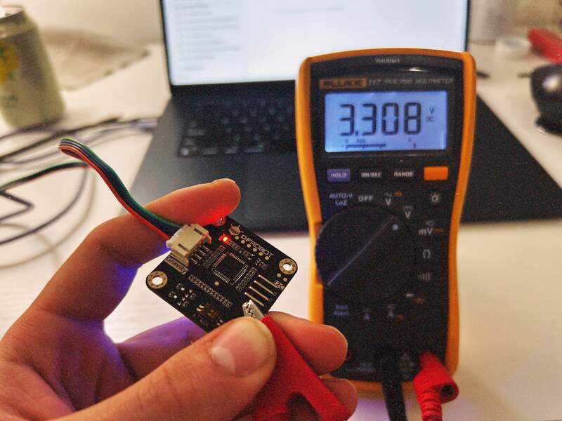
Using multimeter to Confirm input voltage is 3V3
- Multimeter is set to volts DC and ground is connected to convenient location on the evaluation board.
- Reading confirms 3V3 input voltage to encoder