7. Computer Controlled Machining: Girls
Overview
| Assignment | Name |
|---|---|
| Safety training | Angel Fang |
| Runout | Elle Hahn |
| Alignment | Angel Fang |
| Fixturing | Zaina Gibrine |
| Speeds and Feeds | Amalia Bordoloi |
| Materials | Jenna Chebaro |
| Toolpaths | Kathryn Wu |
| Thickness Gauge | Angel Fang and Kathryn Wu |
Resource Links
Materials - Jenna
We use 1/2 inch and 3/4 inch wood for the Shopbot. 1/2 inch is standard for structures that are smaller and/or require less reliability. One would use 3/4 inch for a steadier structure that one typically sits or stands on. Shopbots can also mill plastic, aluminum, foam, as well as composite materials. The material must be flat and aligned, and the bit must be changed accordingly.
Safety Training – Angel Fang
Mr. Dubick and Dr. Taylor did a serious safety training with us at the beginning of the week.
They told us we MUST wear goggles and earmuffs when we go into the wood working room.

They also told us there are two warning lines around the ShopBot CNC machine, we must not across it when we do the wood cutting.

For the big ShopBot, they told us we need to disengage the spindle if we are not using it. After engage the spindle, we need to use the “Start” Button to turn on the spindle.

They also asked us to have at least two people in the room while we are using the CNC machine. In case the wood would accidentally fly in the air, they told us to wear a face shield when we are cutting.
Speeds and Feeds – Amalia
Speeds and feeds in CNC machining determine the cutting tool’s performance, efficiency, and longevity.
Spindle speed (RPM) refers to how fast the tool or workpiece rotates and is based off the tool diameter and material-specific surface speed (SFM).
Feed rate (IPM or mm/min) determines how quickly the tool moves through the material and depends on chip load, tool flutes, and RPM.
Material can play a role in the best setting to use. Harder materials like steel require lower speeds and higher torque, while softer materials like aluminum allow for higher speeds. Small tools typically need higher RPM, unlike larger tools which operate at lower speeds to manage heat buildup.

Runout - Elle
About
Runout is a rotation inaccuracy which occurs when the tool is no longer aligned with the main axis. In drilling applications, this can result in a bore diameter that is actually larger than the drill’s nominal diameter.
Spindle Runout, or Tool Runout, as it can also be called, is the inaccuracies that cause a tool (in a mill) or workpiece (in a lathe) to spin off the ideal axis. It’s very bad for tool life, so it’s good to know more about it.
Runout is the tendency to spin the tool around a centerpoint that is not the tool’s center. It makes the tool wobble instead of spinning cleanly and increases chip loads.
There are a few different types of runouts with include radial runout and axial runout. Radial unout is when the tool moves slightly up and down along its axis, leading to inconsistent cutting depths. And a axial runout is when the tool moves slightly side to side as it spins, affecting precision and causing uneven cuts.
Reasons for Runout:
A common cause of runout is when machining debris, dirt, chips, etc. enter the spindle and cause interference when the tool is clamped. Furthermore, dirt and damage collets can lead to runout inaccuracy. Lastly, damaged bits and shanks can cause iffuses too. CNC spindle runout can decrease tool life and increase the rate of machining defective parts.
Other Reasons: - Misalignment: The tool or holder isn’t installed correctly. - Worn-out Components: Bearings, collets, or tool holders degrade over time. - Bent or Poor-Quality Tools: A slightly bent tool or low-quality tool holder can introduce runout.
Why a problem
Runout can cause: - Uneven Surfaces: Runout leaves behind uneven or wavy surfaces and this can require extra finishing steps like sanding or polishing, increasing production time. - Poor Accuracy:If the tool doesn’t rotate perfectly, cuts won’t be precise. This means that parts may not meet tight tolerances, leading to defects or rejected workpieces. - Increased Tool Wear and Breakage:If there are alot of renout it will put uneven stress on the tool edges. This can cause tools to wear out faster or even break unexpectedly. - Inefficient Cutting Performance:The machine might need to run at slower speeds to compensate for runout. Poor cutting efficiency means longer machining times and higher costs.
Our Machine
Tyler Russel taught and helped me set up the runout machine that we using in our lab.
 This is our first set up of the runout. This was an incorrect way of setting it up because the ball on the end isn’t touching the the bit. Therefore, to fix this we needed to rotate the device to make sure it was touching the bit fully.
 This is the fixed setup. It is important to make sure the dial is set to zero because it its not then the measure ment will be wrong.
To measure the runout, we took a video of us spinning the bit with our hand. It is imprtant to make sure that the machine is disengaged for saftey reasons. Then we slow down the video later to see what it reached. Once I did that the runout we got was around 3 as the runout for the machine. Once we were done it was important to clean up the device we used. This is a very detailed explanation of the tool.
Thickness Gauge - Kathryn and Angel
Design
I (Kathryn) designed the 0.252-0.27 inch gauge on Fusion360.


I (Angel) designed the 0.492-0.510 inch gauge on Fusion 360. However, because of plan change, boy group and us switched the gauge design. At last, we printed the 0.742-0.760 gauge and 0.252-0.270 gauge.


I exported the drawing as a .dxf file and tried to add dogbone fillets, but the check mark did not show up for certain corners. I realized it was probably because of gaps in the design and Angel let me know that I could solve it easily with the join vectors tool.

And then it worked. But having 0.1 in radius fillets did not fit on both sides, so I went down to 0.075 in. I also added the number labels as text.
For the text, we were planning to use a v-bit to engrave it, but we were worried the woodpiece was too small, so we ended up using a laser cutter to engrave the numbers.

I changed the rest of the settings, but for ramp I wasn’t sure if I should go with the default or not. Chat told me a good ramp distance is 2x to 5x the tool diameter and I’m using the ⅜ compression bit, so I went with 1.8 inches.

I then simulated the toolpath and it looked good.


Milling
When we got to the ShopBot stage, we decided to use the smaller desktop ShopBot because our print would not be too large. We followed this workflow to operate the machine.
These were the windows we used to jog z and zero it to do an air cut.


When it started, we needed to make sure the machine was operating at the right hertz.


Before the final cut, we also did a bit tap off.


These are the finished gauges.

Toolpaths - Kathryn
For the design, I started with 3 1.5 in squares.

After exporting it to Aspire, I changed the toolpath in the toolpath settings. The options were outside, going along the outer edge of the line; on, with the extra width equally on either side of the line; and in, going along the inner edge of the line.


I did the toolpath simulation for these pockets and they seemed good.


The rest of the cutting process was done along with the gauges, so the previous documentation applies. These were the final products of this test.


It turned out how I expected it to, with the outer toolpath setting resulting in the largest square, then on being second largest and inside resulting in the smallest.
Alignment – Angel Fang
The definition of alignment for CNC machining refers to the process that ensures the correct positioning and orientation of the machine’s axes, the workpiece, and the tool in relation to each other to achieve accurate and precise machining operations.
Since our teachers are smart and considerate, they already set up a C3 command for alignment. The C3 command is used to home the machine and reset the z-zero height to the machine bed. So there is no need for us to do alignment manually.
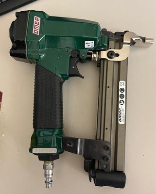
Fixuring
In our lab we used plastic brads to fasten are material to the shopbot board.
What are brads?
Brads are small, thin nails typically used in woodworking, and they can be useful for ShopBots in specific applications. Here’s how they might be used:
Workpiece Hold-Down: When cutting thin or flexible materials on a ShopBot, brads can help secure the workpiece to the spoil board, preventing movement during milling.
Temporary Fixturing: In cases where clamps are impractical, brads can be used to track down material temporarily. This is especially useful for cutting small parts that might move.
Registration and Alignment: Brads can serve as alignment pins to ensure the accurate placement of multiple workpieces or layers in a project.
Holding Onion-Skinned Pieces – When using an “onion skin” technique (leaving a thin layer of material uncut), brads can prevent pieces from breaking free before the final pass.
How do you install a brad?
Here is a step-by-step tutorial from our instructor to install a brad Put on eye and ear protection. 1. Close the doors. 2. Secure your material to the machine spoil board using the composite nail gun (and teacher’s help) if this has not already been done for you.
-
Please be sure that the red air compressor tank valve is closed (see image)

-
Turn on the red air compressor (see image). Please be sure to allow the tank to fill completely, so that your brad nails will fully drive into the material.

-
Retrieve the brad nailer from under the computer in the cabinet.
-
Attach the neon yellow air compressor hose to the nailer’s air inlet (see images).


-
Set the compressor to the appropriate PSI (see a teacher for the recommended pressure).
- Load the brad nailer by opening the magazine by locating the magazine latch, releasing it, and sliding the magazine open.
- Place the appropriate length brad nails into the magazine with the pointed ends facing outwards.
- Close the magazine by sliding it back until it locks securely.
- Position the nailer by placing the safety tip flat against the work surface where you want the nail.
- Hold Firmly and grip the handle with one hand, ensuring a firm and steady hold.
- Fire the nail by squeezing the trigger while keeping the safety tip pressed against the surface.
- Check the nail placement and confirm that the nail is driven to the correct depth.
- With a teacher If the nail does not go in far enough, increase the PSI by using the depth adjustment dial on the tank to ensure nails sit flush with the surface.