
Final Project
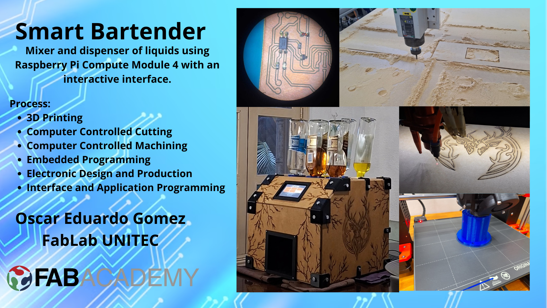
My final project is a Smart Bartender, a robotic system that can prepare a variety of cocktails and drinks. The Smart Bartender will be equipped with a user-friendly interface, allowing users to select their desired drink and customize the ingredients and proportions. The system will feature a d ispensing mechanism to accurately measure and pour the ingredients, ensuring consistent quality and taste. Additionally, the Smart Bartender will include sensors to detect the presence of a glass and adjust the serving size accordingly. The project aims to combine my interests in robotics, automation, and mixology to create a fun and interactive experience for users.
The purpose of this project is to explore the integration of hardware and software to create an automated system that can perform a specific task. By combining mechanical components, sensors, and a user interface, the Smart Bartender will demonstrate the potential of robotics and automation in everyday applications.
The main idea appers from the need to create a system that can prepare drinks in a fast and efficient way, this to avoid waste time in the preparation of the drinks when you spend time with your friends or family, also to avoid the waste of the ingredients, because the system will be able to measure the exact amount of each ingredient.
Sketch
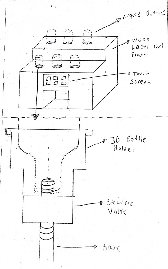
The first step in the design process is to create a sketch of the Smart Bartender. This sketch serves as a visual representation of the project, outlining the key components and features. The sketch includes the main structure of the Smart Bartender, as well as the dispensing mechanism, user interface, and sensors. By creating a sketch, I can visualize the project and plan the design and development process.
Time Management
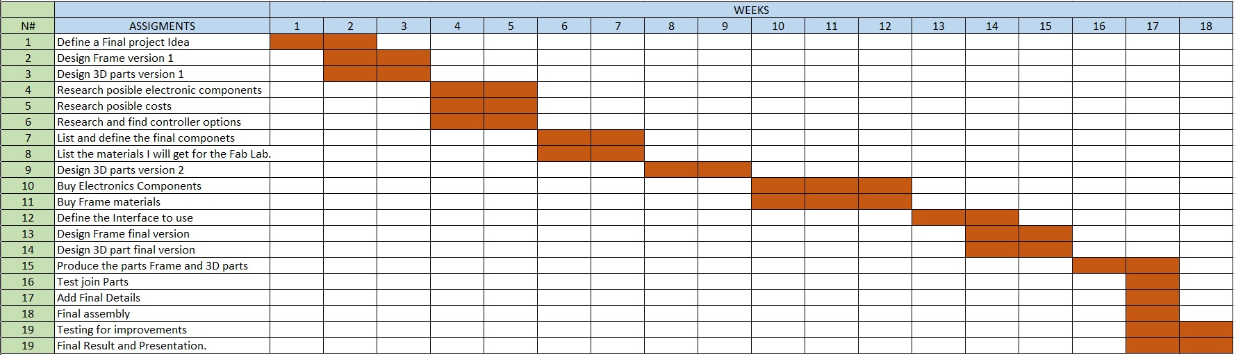
In the next table, you can see how I will organize the upcoming weeks to work on the final project. This is really important to complete the project on time and be ready for the presentation.
Components
The Smart Bartender will consist of several key components, each serving a specific function in the system. The main components include:
- Frame: The main structure of the Smart Bartender, providing support and housing for the other components.
- Dispensing Mechanism: A system for accurately measuring and pouring the ingredients, ensuring consistent quality and taste.
- User Interface: An interactive interface for users to select their desired drink and customize the ingredients and proportions.
- Sensors: Sensors to detect the presence of a glass and adjust the serving size accordingly.
Designing
The next step in the design process is to create the components of the Smart Bartender. This involves using CAD software to design the frame, dispensing mechanism, user interface, and sensors. The components will be designed to fit together and function as a cohesive system.
To design the components, I will use SolidWorks, a 3D modeling software that allows me to create detailed and precise designs. I will create each component individually, ensuring that they are compatible and can be assembled together. The design process will involve creating sketches, extruding features, and adding details such as fillets and chamfers.
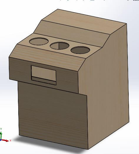
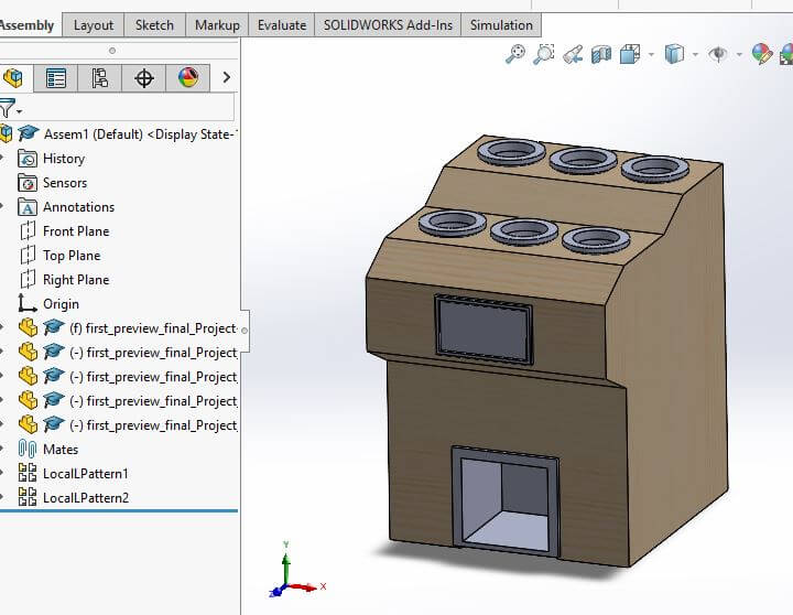
This design can provide us a first view of the Smart Bartender, in this view we can see the main components of the project, the frame, the bottle holder, the screen, and the glass holder, this view is created with the assembly option in SolidWorks, and some mates to locate the components in the correct place and orientation.
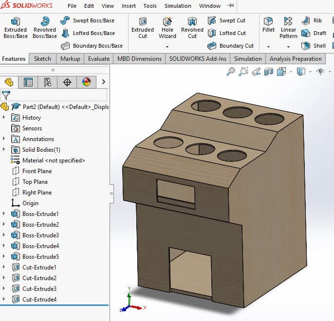
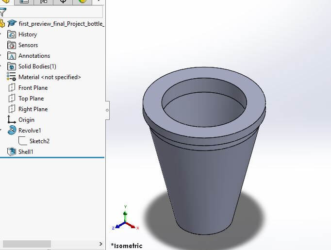
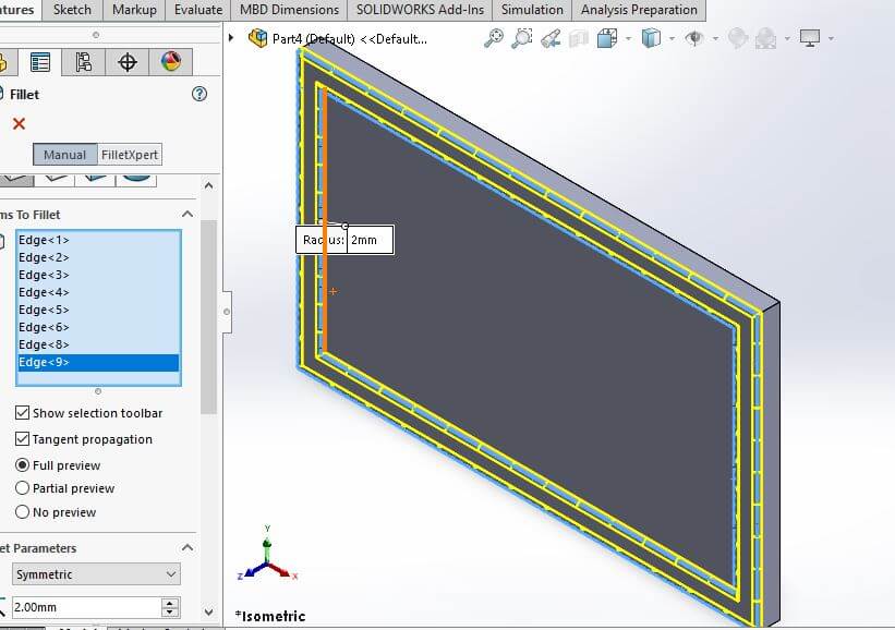
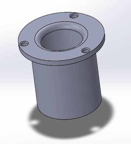
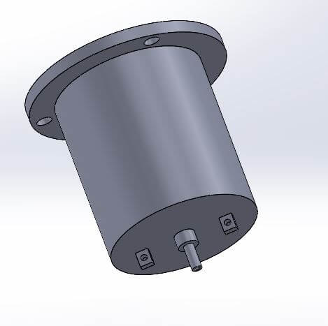
To create the rest of the parts of the Smart Bartender, we explore some tools solidworks provides us, in this case, we use the revolve tool to create the bottle holder, to create the screen we use the extrude tool and the fillet tool to give a better appearance to the components.
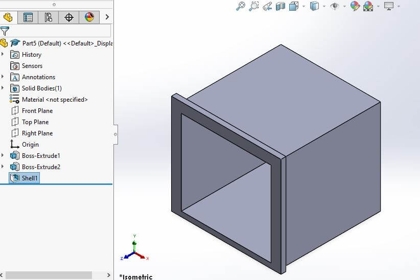
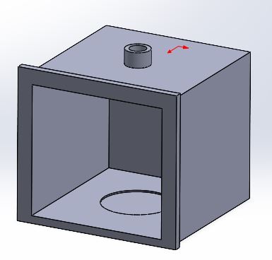
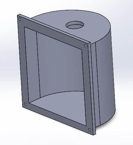
The last part of the Smart Bartender is the glass holder, for this we use the shell tool to create the hole where the glass will be placed, then this part is going to be able to be sense if we have a glass or not, the main idea it's to create the last three components with 3D printing.
In this last image, you can see the final view of the Smart Bartender, with all the components together, this is the first view of the project, to create this view we use the assembly option, and some mates to locate the components in the correct place and orientation, also tools like local pattern to create the bottles holders with just one instance.
2D Design
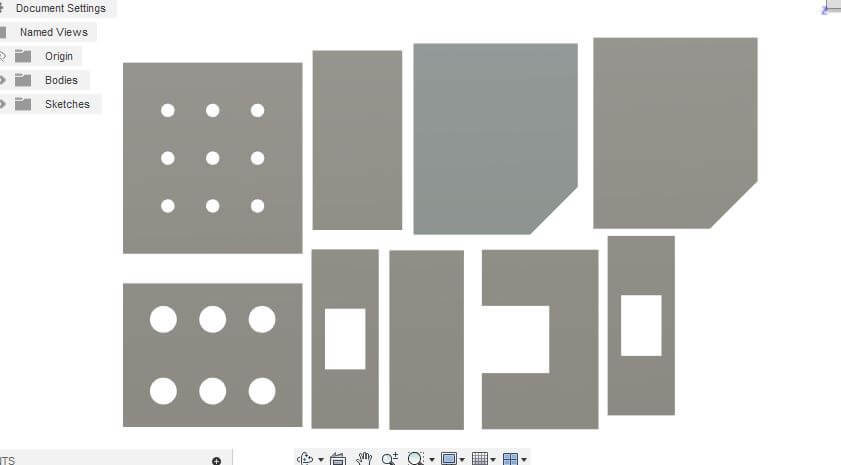
In this case, ones I have the main idea of the 3D model, I can create a 2D design to cut it with a laser cutter in the future if it is needed, the software I'm goind to use is Ilustrator, this software is a vector graphics editor and let us create vector and edit images, text and other elements. I selected this software because I own a student license because I'm using a .edu email account. Also I have used it in the past, so I have some experience.
The first step is to create a new document, then we select the size of the document, this size in particular could be A4, A3 or any other size that we want, I created a custom size document of 1200 x 2400 mm, this is the size of a commercial wood sheet.
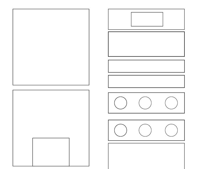
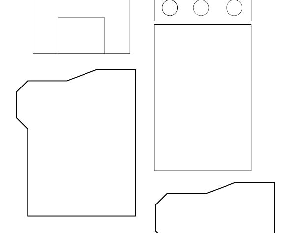
After creating the document, we can start creating the vector design, for this, I used the shapes tool to create the frame I needed. Also, something to consider is set the document settings into the units we are going to use, to my file I set the units to centimeters.
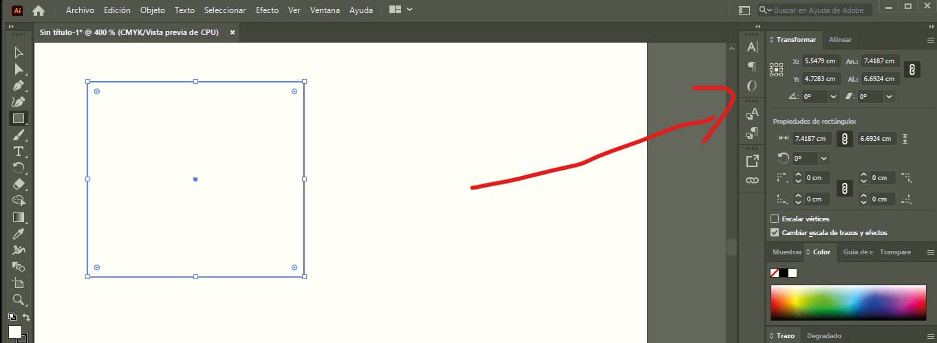
After a while, I created the shapes I needed, as you can see in the next images, I created a first iteration of the frame, this will alow me to test in the future.


First Version Project Files links
In the next links, you can download the files and the assembly for the Smart Bartender.
- Wood Frame (First Preview)
- Bottle Holder
- Screen
- Glass Holder
- Complete Assembly
- Wood Frame Ilustrator File
- Wood Frame PDF file
Hardware Components – Smart Bartender
| Component | Description | Fabrication Method |
|---|---|---|
| Wooden Frame | Main structure housing all components | Laser Cut |
| 3D Printed Joints | Connectors for frame stability | 3D Printed |
| Raspberry Pi | Main controller running the UI and automation logic | Purchased |
| Touch Screen | Interface for user interaction | Purchased |
| 3D Printed Screen Frame | Holder/enclosure for the touch screen | 3D Printed |
| 3D Printed Bottle Holders | Secures bottles on the top panel | 3D Printed |
| 3D Printed Cup Base | Base for placing the cup under the dispensing valves | 3D Printed |
| Solenoid Valves | Controls liquid flow from bottles | Purchased |
| Control PCB | Custom PCB to control solenoid valves | Designed & Fabricated |
| Power Supply | Provides power to all electronic components | Purchased |
| DC-DC Regulators | Voltage conversion for components | Purchased |
| Plastic Tubes | Connects bottles to solenoid valves and cup | Purchased |
The components listed above are the main parts of the Smart Bartender system. Each component plays a crucial role in the overall functionality and design of the project. The wooden frame provides the structure, while the 3D printed parts add custom features.
The Raspberry Pi serves as the brain of the system, controlling the touch screen interface and automation logic. The solenoid valves manage the liquid flow, and the custom PCB ensures proper control of these valves. The power supply and DC-DC regulators provide the necessary power to all components. Finally, the plastic tubes connect the bottles to the solenoid valves and the cup, ensuring a seamless dispensing process.
The integration of these components is essential for the successful operation of the Smart Bartender system. Each part must work together harmoniously to create a functional and efficient automated bartending solution.
The first Step was to create the wooden frame, which serves as the main structure for the project. The frame is designed to house all the components securely and provide stability during operation. The frame is made from high-quality wood, ensuring durability and strength.
The software used to create the frame is Ilustrator let us create the design and save it as a SVG file.
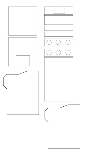
In the next images, you can see the design of the frame ready to be cut, however before cutting it, I had to make sure that the design was correct and that all the parts fit together properly. To do this, I'm planning create a scaled down version of the frame using cardboard. This will allow me to test the design and make any necessary adjustments before cutting the actual wood.

For the 3d printed parts, I used Solidworks to design the components. The 3D printed parts include the joints for the frame, the screen holder, and the bottle holders. These parts are designed to fit perfectly with the wooden frame and provide additional support and functionality.
The 3D printed parts are going to be printed using PLA material, which is known for its strength and durability.
In the next video, you can see the distribution of the frame and the 3D printed parts, providing a preview of how the entire machine will look when assembled.
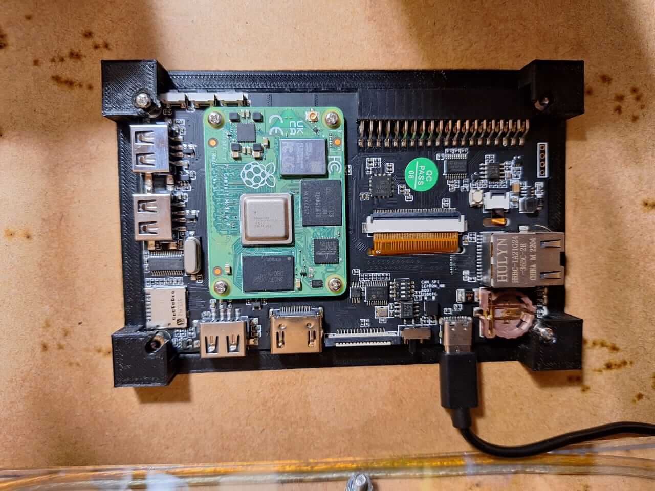
For the electronics, I used a Raspberry Pi as the main controller for the system. The Raspberry Pi is responsible for running the user interface and automation logic.
The raspberry pi is going to manage a control PCB that I designed. The control PCB is responsible for controlling the solenoid valves that manage the liquid flow from the bottles.
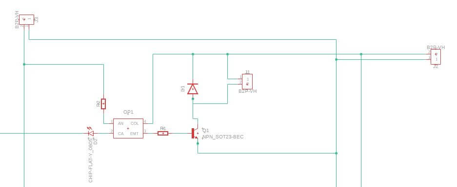
The PCB is designed in Fusion 360 with has the components needed to control the solenoid valves. the main circuit is going to be based on a octocoupler and transistor that is going to control the solenoid valves. This let us use different voltages for the solenoid valves and the raspberry pi.
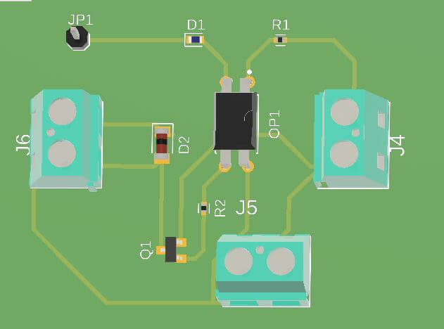
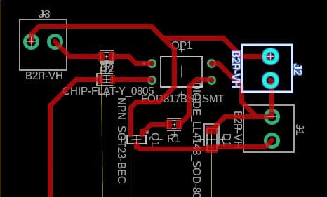
Before creating the final PCB, I decided to create a test board. This board can control only one solenoid valve. The main idea is to test the SMD components and also the valve. The circuit contains two parts: signal control using 5V to manage this part of the circuit, and power control working with 12V to manage the solenoids.
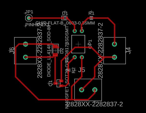
This is the final result or how it looks in the 3D simulation. This allows us to verify if we used the correct components, sizes, path widths, or any details that could affect the performance.
The same circuit is commonly used to control relays, so almost all commercial relay boards will work with this circuit. As you can see in the next picture, this is a typical circuit for a relay module, but in our case, I'm not using relays; I'm controlling the solenoid directly.
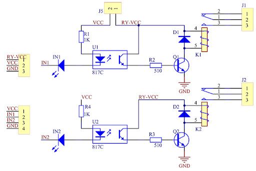
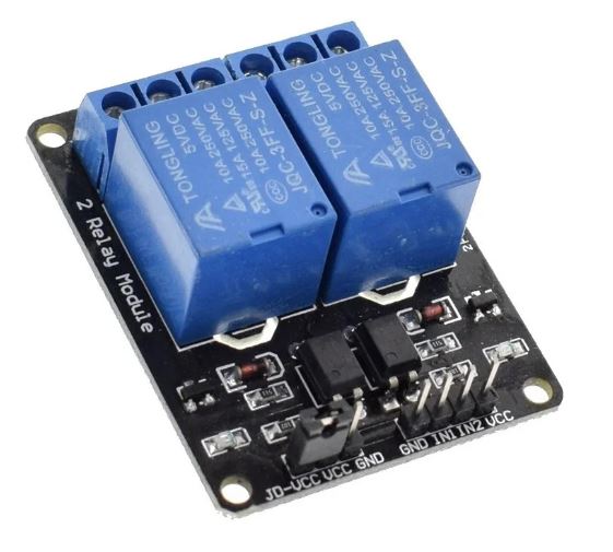
Image Circuite source Circuit Reference
Image Relay source Circuit Reference
The circuit it's really simple some of the components I'm using:
- Resistor
- Diode
- Transistor NPN
- octocoupler
- LED's
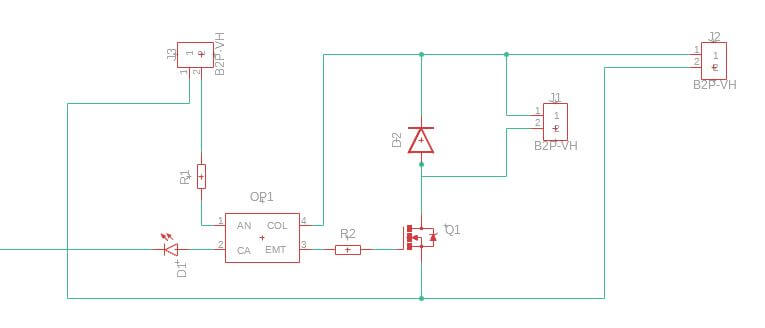
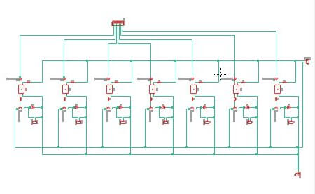
Discussing how everything is going to be connected, I created the following diagram showing the distribution of the electronic components. This is just a preview to test the concept, but when I add the rest of the solenoid valves, the circuit will follow the same design with additional Raspberry Pi signals.
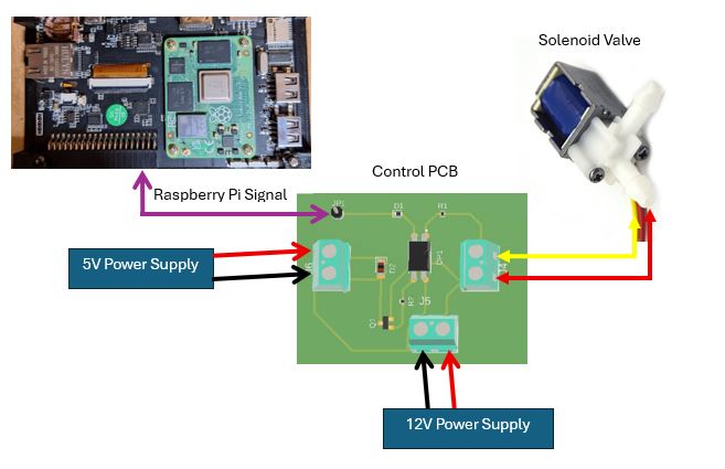
Explaining how everything works: once we select some options on the Raspberry Pi screen, it sends a signal through the GPIO OUTPUT. This signal activates the LED and the optocoupler. As a result, the output of the optocoupler activates the transistor, which then activates the solenoid valve, opening the hose to allow the liquid to flow.
In the coming weeks, we need to test and design the entire hydraulic system and observe how the system performs when incorporating the six solenoid valves required for the complete setup.
Issues
Based on the SMD design for the PCB, finding the components needed for the PCB is a bit challenging because, in my country, the components are not readily available. I need to order the components from other countries, which will take a lot of time. However, to avoid this problem, I can use components from a commercial relay board. These kinds of boards are available in my country and are easily found in the Arduino market in my city.
Second Project Files links
In the next links, you can download the files for the assignments.
Questions about final proyect
What will it do?
My final project will be a Smart Bartender that automates the process of making cocktails. It will be able to mix different ingredients, measure them accurately, and serve the drinks with precision. The project will integrate various technologies such as microcontrollers, sensors, and actuators to create a fully functional machine. The main idea is to provide a user-friendly interface that allows users to select their desired cocktail, and the machine will prepare it automatically. I decided to create this project because I am passionate with technology and enjoy experimenting with different flavors and combinations in cocktails. The Smart Bartender will not only enhance the cocktail-making experience but also showcase my skills in electronics, programming, and design.
Who's done what beforehand?
Some Ideas I found of previous students in the Fab Academy that are similar to my project are:
- Mayra Alejandra Mamani López's Drink Mixing Machine
- The Gang Makes a Drinking Machine
- Drink Mixing Machine by EECS Shop Section
Mayra's project focuses on creating a drink mixing machine that automates the process of combining two different liquids. something really interesting about her project is that she used a MDF sheet of 12mm thickness to create the structure of the machine, which is a great choice for stability and durability.
This project involves a group of students who collaborated to create a machine that can mix drinks. Something I liked about this project is that they used a gravity-fed system to dispense the liquids, also they incorporated servo motors to control the valves that release the liquids, however, they used a moving platform to move the cups into position, somethin that I would like to avoid in my project.
This project like the previous one, involves a movile platform that moves the cups into position, however, they used pumping system to dispense the liquids, which is a different approach compared to the gravity-fed system used in the previous project. Using a pumping system can provide more control over the flow rate and volume, however, it can also increase the cost and complexity of the machine.
What sources will you use?
To define the electronic circuit of my project, I will use the following sources:
- Arduino Forum - Here some users dicussed the components and schematic of a relay board, which is essential for my project because I will use the same circuit to manage the coils of the solenoid valves, because has the same functionality as a relay, being both coils devices that can be controlled by a microcontroller.
- Raspberry Pi documentation - This documentation provides detailed information about the Raspberry Pi, including its hardware specifications, software setup, and programming guides. The main idea is to use the Raspberry Pi as the main controller for my project, allowing me to control a touch screen interface and manage the cocktail recipes.
- thecocktaildb - This is a website that provides a comprehensive database of cocktail recipes. I will use this resource to gather information about different cocktails, including their ingredients and preparation methods.
What will you design?
In my project, I will design the following components:
- Electronic Circuit: I will design the electronic circuit that will control the solenoid valves.
- Interface: I will design a user-friendly interface that will allow users to select their desired cocktail.
- 3D Models: I will create 3D models of the machine's components, including the structure, solenoid valve holders and rest of the parts that will be fabricated.
- MDF Sheet 5mm
- Bolts and nuts
- 3D Printing Filament
- Hose Tube
- Solenoid Valves
- Raspberry Pi
- Touch Screen Display
- DC-DC converter
- DC power supply
- Limit Switch or light sensor
- Wires
- SMD Electronic components: Resistors, transistors, optocouplers, connectors and LEDs
- La Mundial & Larach: I will purchase the MDF sheet, bolts, nuts, and hose tube from differents local hardware stores such as La Mundial and Larach, which are well-known suppliers in my area.
- C&D TecHNologia: I will purchase the solenoid valves, Raspberry Pi, touch screen display, DC-DC converter, DC power supply, limit switch or light sensor from this store is the only option in my city that sells these components.
- FabLab: I will also use the resources available at the FabLab like the 3d filament, wires and SMD electronic components.
- Frame: I will fabricate the frame of the machine using MDF sheet.
- Bottle and Solenoid Valve Holders: I will 3D print holders for the bottles and solenoid valves to ensure they are securely mounted and aligned.
- Cup Holder: I will design and 3D print a cup holder that can also detect when a cup is placed in position using a limit switch or light sensor
- Screen Enclosure: I will design and 3D print an enclosure for the touch screen display to protect it and integrate it into the machine.
- PCB: I will design and manufacture the PCB that control the solenoid valves.
- 3D Printing: I will use 3D printing to create the holders for the solenoid valves, cup holder, screen and joins for the frame.
- Laser Engraving: I will use laser engraving to create decorative elements and labels for the machine.
- CNC Machining: I will use CNC machining for the frame of the machine, and also for the PCB production.
What materials and components will be used?
The list of materials and components I will use in my project includes:
Frame
Electronics
Where will they come from?
The materials and components for my project will be sourced from the following places:
How much will they cost?
The estimated budget for my project is as follows:
| Component | Price (Lempiras) | Price (USD) |
|---|---|---|
| MDF Sheet 5mm | L.550.00 | $22.00 |
| Bolts and Nuts | L.300.00 | $12.00 |
| 3D Printing Filament | L.1200.00 | $47.00 |
| Hose Tube | L.400.00 | $67.00 |
| Solenoid Valves (6 units) | L.900.00 | $35.00 |
| Raspberry Pi | L.1,560.00 | $60.00 |
| Touch Screen Display | L.1850.00 | $72.00 |
| DC-DC Converter | L.300.00 | $12.00 |
| DC Power Supply | L.850.00 | $33.00 |
| Limit Switch or Light Sensor | L.200.00 | $8.00 |
| Total | L.9,310.00 | $380.00 |
Something important to consider is that the prices of the components may vary depending on the supplier and the availability of the components, also part of the components I will use will be provided by the FabLab, such as the 3D printing filament, wires and SMD electronic components, Raspberry Pi and the touch screen display, which will help to reduce the overall cost of the project.
What parts and systems will be made?
The parts and systems that I will fabricate or assemble for my project include:
What processes will be used?
The processes I will use in my project include:
Programming
In the interface I'm creating, I'm using a Raspberry Pi CM4, so I set up a simple OS provided by the same branch. This is really helpful because it is a Linux-based OS and allows us to control all the registers or simply use the kernel or libraries to interact with the outputs and inputs of the module.
For this project, I'm using Python because it's a simple language, and Raspberry Pi has a lot of libraries to interact with the hardware directly. Some disadvantages of this are that if the program is too complex or large, the system could be slow compared to using C++. However, for our requirements, using Python is more than enough.
I'm going to use the Python library RPi.GPIO to interact directly with the GPIOs. This is a very helpful library because we don't need to work directly with the registers. It allows us to set a specific pin as OUTPUT or INPUT to sense something or control a valve, as in our case. For the interface and to create buttons on the screen and interact with the touch, I'm using tkinter and PIL. These two libraries let us create graphic interfaces and process images, for example, adding a background image or a button to select a valve.
Example of how to use the libraries on a Raspberry Pi with Python
                        import tkinter as tk  # To create graphic interfaces
                        from PIL import Image, ImageTk # To manage or manipulate images
                        import RPi.GPIO as GPIO # To interact with the Raspberry Pi GPIOs

                        # You can also add more libraries depending on your algorithmic needs
Source: Github Repository
Tasks Completed
- Tested the electronic components and parts.
- 2D frame designed.
- 3D parts designed.
- Hydraulic design completed.
- Set up the OS for the Raspberry Pi, in this case, Linux.
- Touch screen tested and working.
Tasks Remaind
- I need to complete the PCB control module.
- I need to cut the final frame; I already have all the materials.
- I need to print the remaining 50% of the 3D parts.
- Once assembled, I need to test the hoses and how the liquids move through the hydraulic system.
- I need to finish the interface and test the outputs.
What has worked and what hasn´t?
At this point, almost 60% of the system works as expected, including the solenoid valves, the Raspberry Pi, and the test PCB. However, something I am unsure about is whether the hoses I selected will work effectively. The main idea is to use gravity to move the liquids, but the internal diameter of the hoses is small, which could make the system slow. In that case, I have the option to add a pump to create vacuum in the system, but this is just a backup plan, and we need to test everything assembled first. Additionally, something that is not working right now is the cocktail database, which is incomplete and requires a lot of work. As a backup, I plan to create a manual interface that allows users to select the liquid manually and then dispense it.
What questions need to be answered?
- How can I ensure the solenoid valves operate reliably and accurately?
- How can I ensure the machine is safe to use, especially when dealing with liquids and electronics?
- What testing methods can I use to evaluate the accuracy of liquid measurements?
- How can I make the machine user-friendly and intuitive?
How will it be evaluated?
The project will be evaluated if:
- The machine operates reliably without errors or malfunctions.
- The user interface allows users to select cocktails easily.
- The solenoid valves dispense liquids with precision, ensuring accurate measurements for cocktails.
- The machine can detect the presence of a cup using a limit switch or light sensor before dispensing liquids.
What have I learned?
Things I have learned throughout this process include time management and the importance of documentation. Proper documentation helps avoid repeating past mistakes and provides a clear overview of progress and remaining tasks. This is crucial for identifying issues or problems during integration more quickly and making prompt changes to resolve them.
CNC Routing
The main task for this week is to finish or at least complete 90% of the final project to be ready for the final presentation. In my case, the project is a smart bartender or liquid dispenser machine, and I have almost everything ready for the final assembly and testing. So, let's start.
After working on some 3D part designs and versions of the frame, I made some changes. Let me explain a little bit about this. Let's go to the latest version. In the case of the frame, we have the following version:
However, this version is complex when it comes to joining each part. To reduce complexity, I changed the top part of the machine and gave it a simpler design, allowing for the addition of other details. The final frame looks like this.
The changes are minimal but significantly reduce production and assembly time. Now, with the final version ready, it's time to use the CNC machine to cut the frame.
3D Printing
Now I have the frame it's time to create the 3D parts, I add some details to the previous versions of the 3D parts I designed just to reduce time and also to fit the new frame.
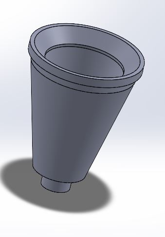
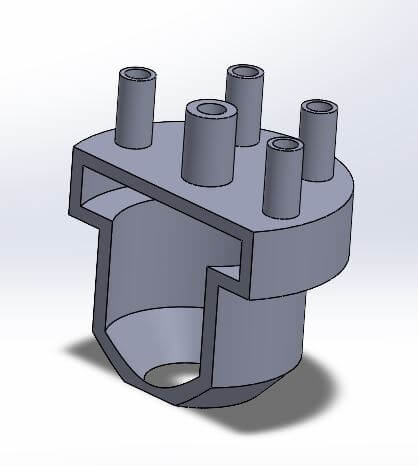
In these first images, you can see the bottle holder and the cup holder. These parts are the most important in the system because they are the ones visible from the outside and the ones in contact with the liquid.
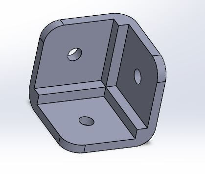
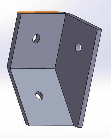
The following images show the 90-degree joints and edge connections, as well as the extruder. This specific part is placed on top of the cup holder and helps direct the liquid.
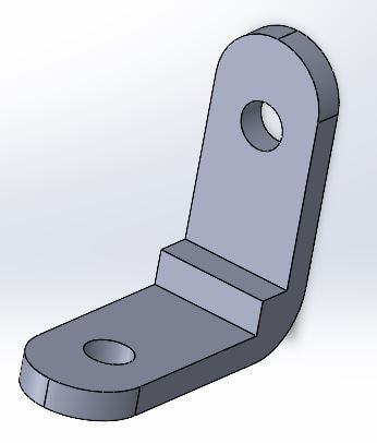
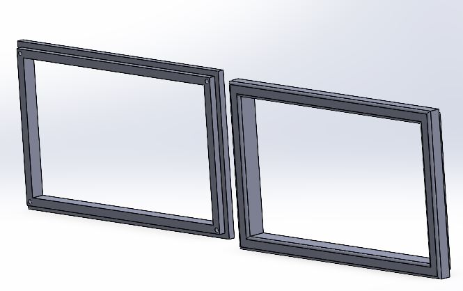
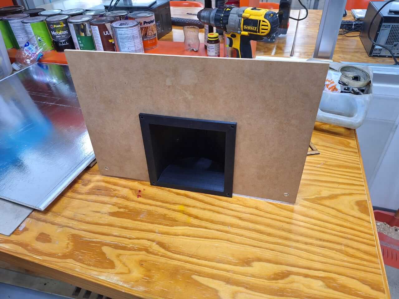
The last parts are the angle joint and the screen holder. This is a nice frame that allows us to add the touchscreen to the frame without too many parts.
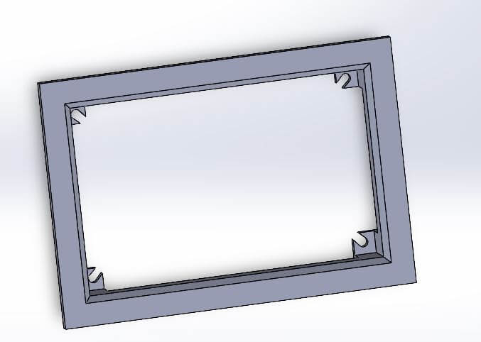
Now I had everything ready. It's time to print all the parts. For this, I used almost five printers, including Ender 3 and Prusa models, with an estimated print time of 90 hours to get everything ready.
After printing, I tested how some parts fit into the frame.
With the frame and the 3D parts ready, it's time to assemble. However, there are two things to do first: prepare the electronics and add some finishing touches to the frame.
PCB Production
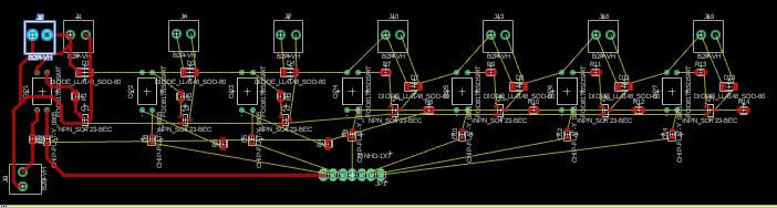
I started with the electronics. The first step was to design the PCB. As you saw a few weeks ago, I created a small version. This one is ready to control the six solenoid valves I am going to use. The design is the same; the only change is the quantity, making it bigger. Additionally, I added one input for 5V and one for 12V.
With this ready, it's time to route and create the G-code files for production. Let's review the process.
Now, we start the milling process and solder the components.
And this is the result of the milling process.
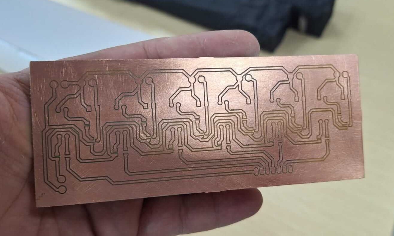
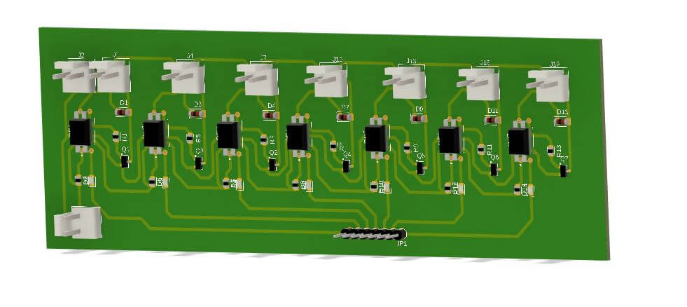
With the PCB ready, I started adding the SMD parts to ensure everything works correctly.
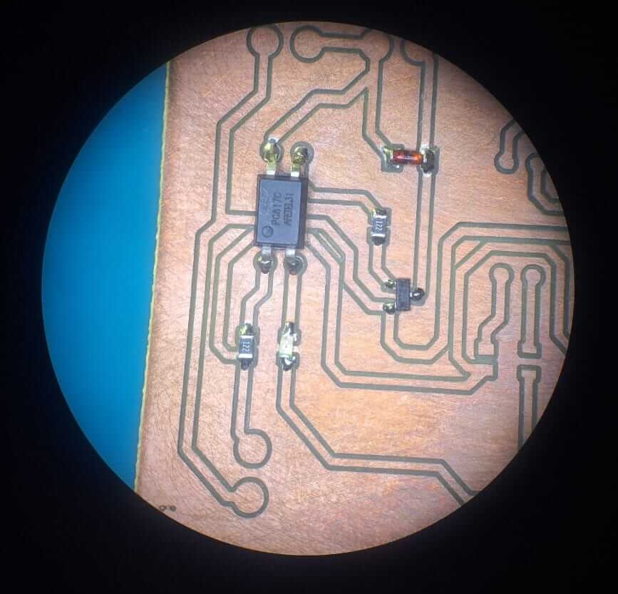
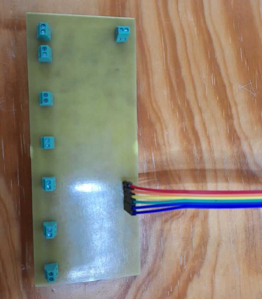
PCB finished with all the SMD components, now it's time to connectors and terminals.
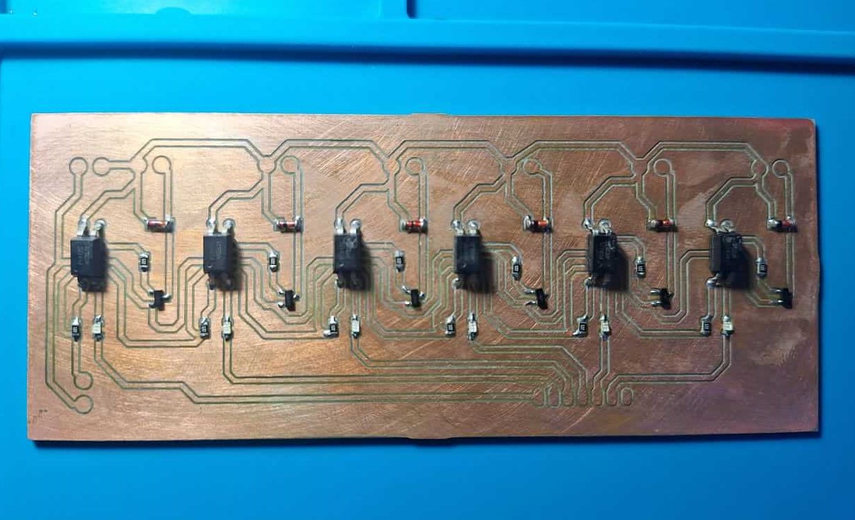
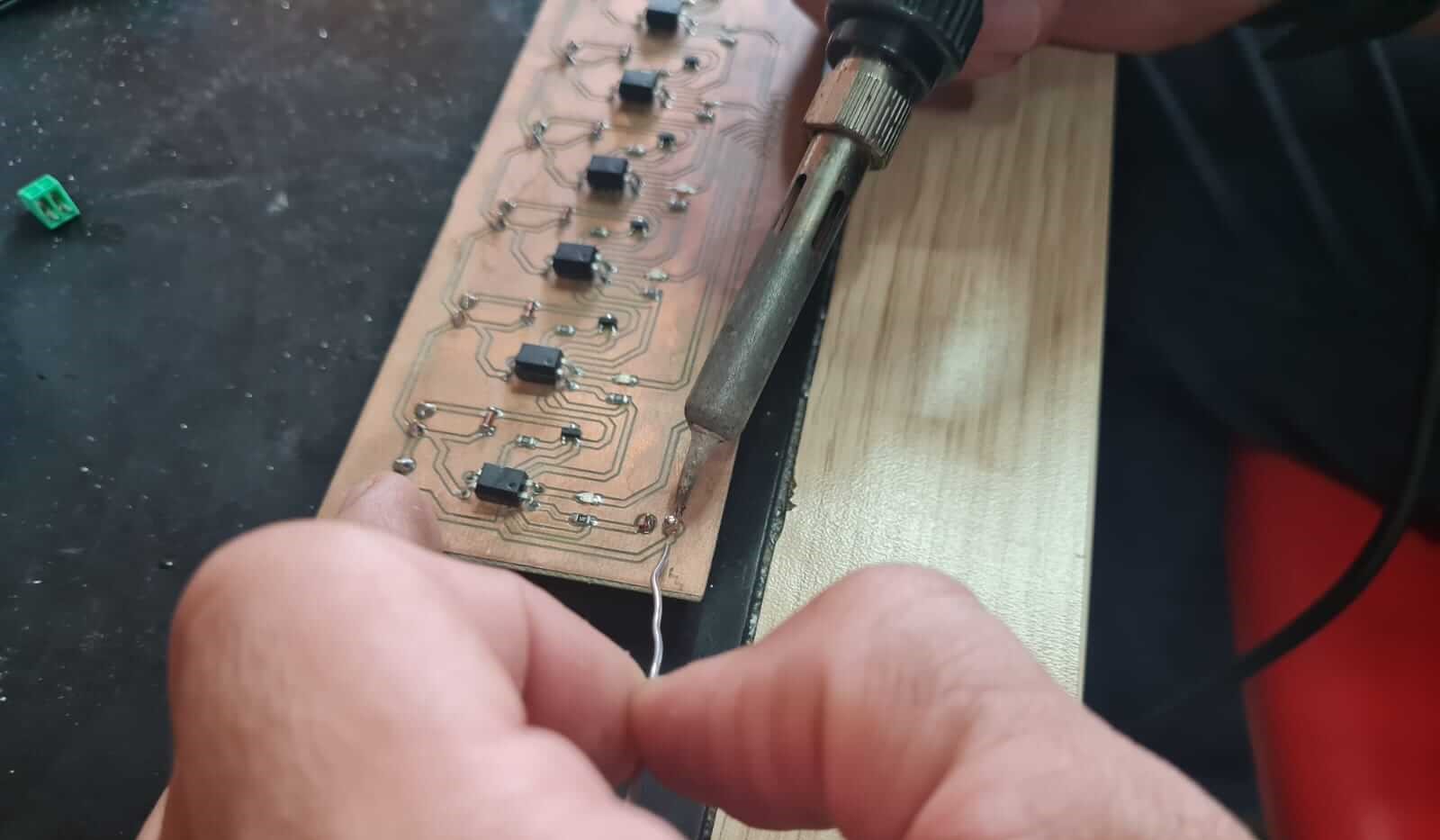
The result of all the PCB process
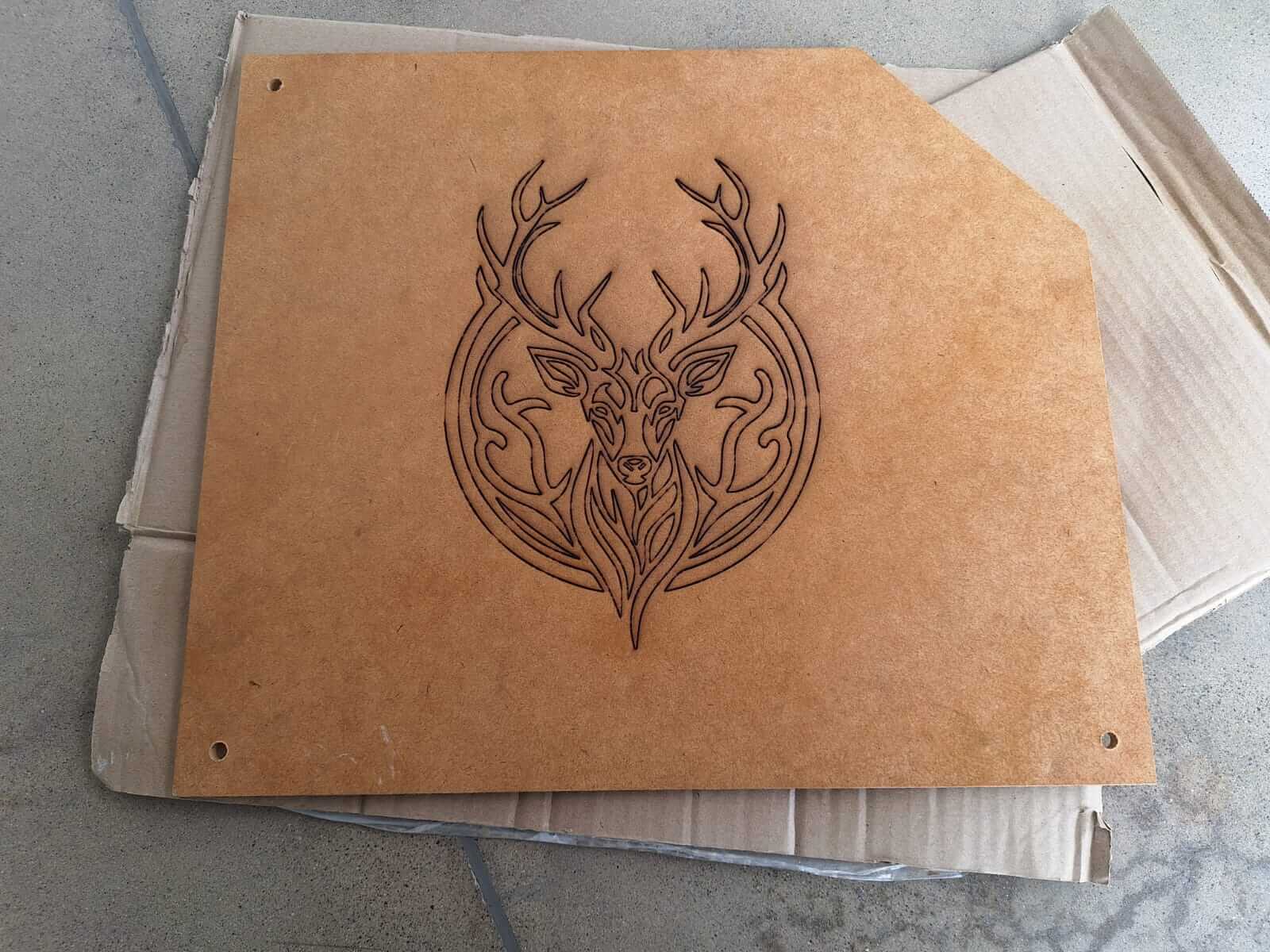
Now it's time to give a good finishing touch to the frame, to do this I used laser engraving and also added clear to the MDF to give a shadow effect looking like wood.
The result?
It's time to assemble everything and start seeing how all the hard work comes together.
Integration
So, this is how it looks assembled and testing how the bottles fit. It looks pretty good.
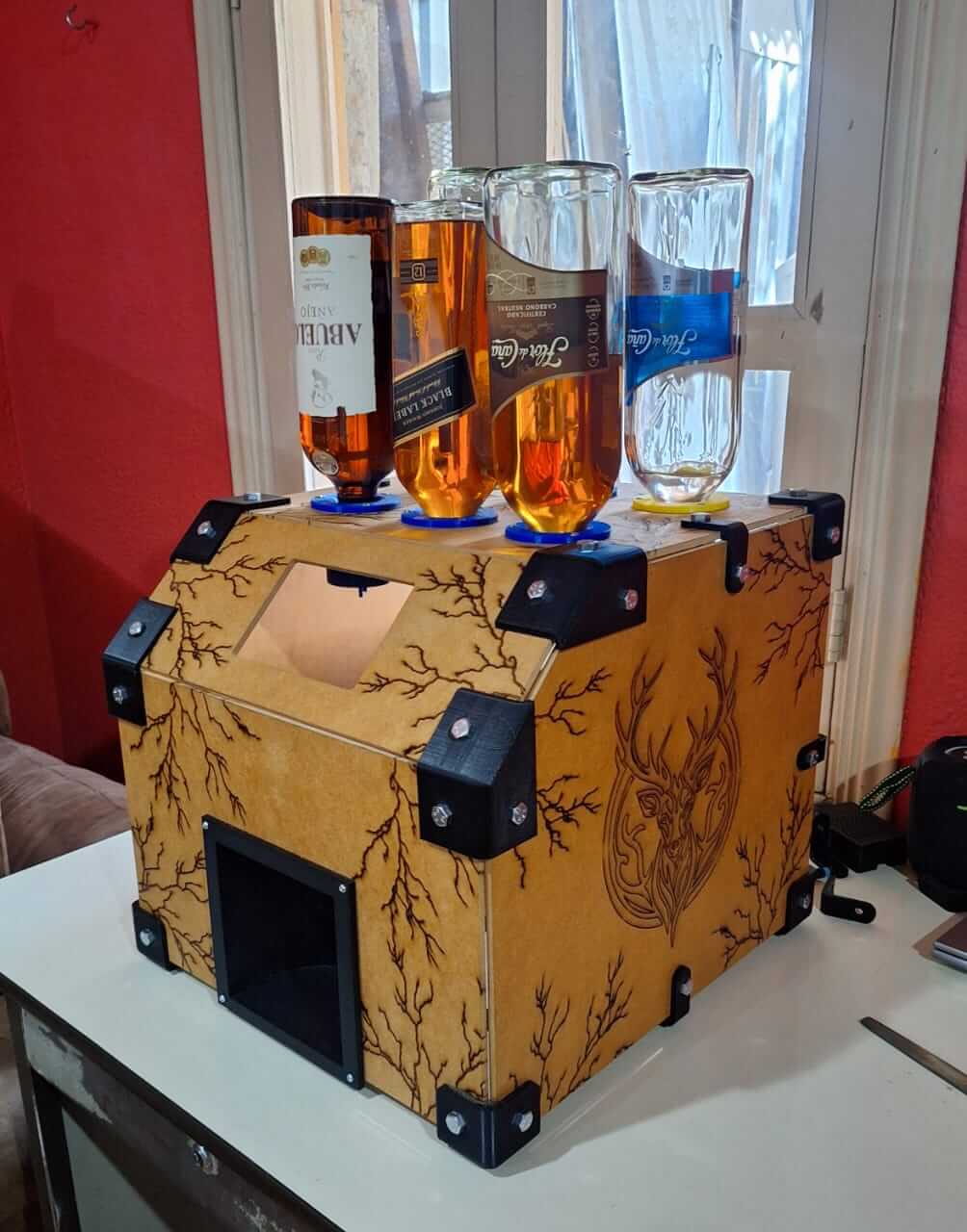
I also started adding some details to make it look more like a commercial product. In this case, I added a switch with a connector and a fuse to turn the machine on and off.
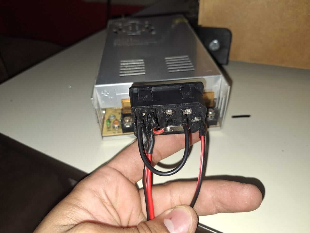
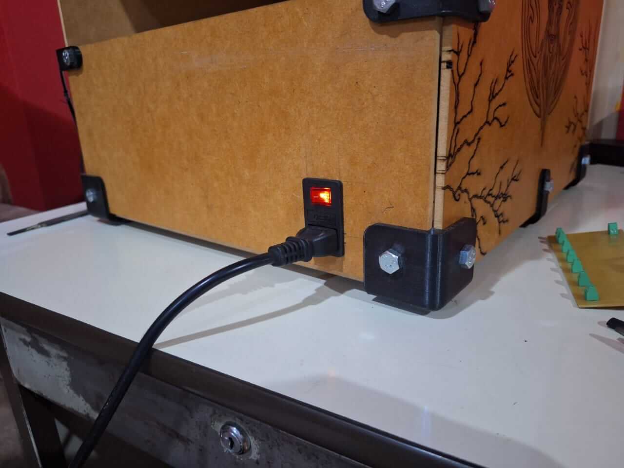
This helps us to turn on the power supply. It is a 12V unit with 30 amps. I used this large power supply because it was the only one I had available, and I couldn't purchase another one, so it was time to recycle, haha.
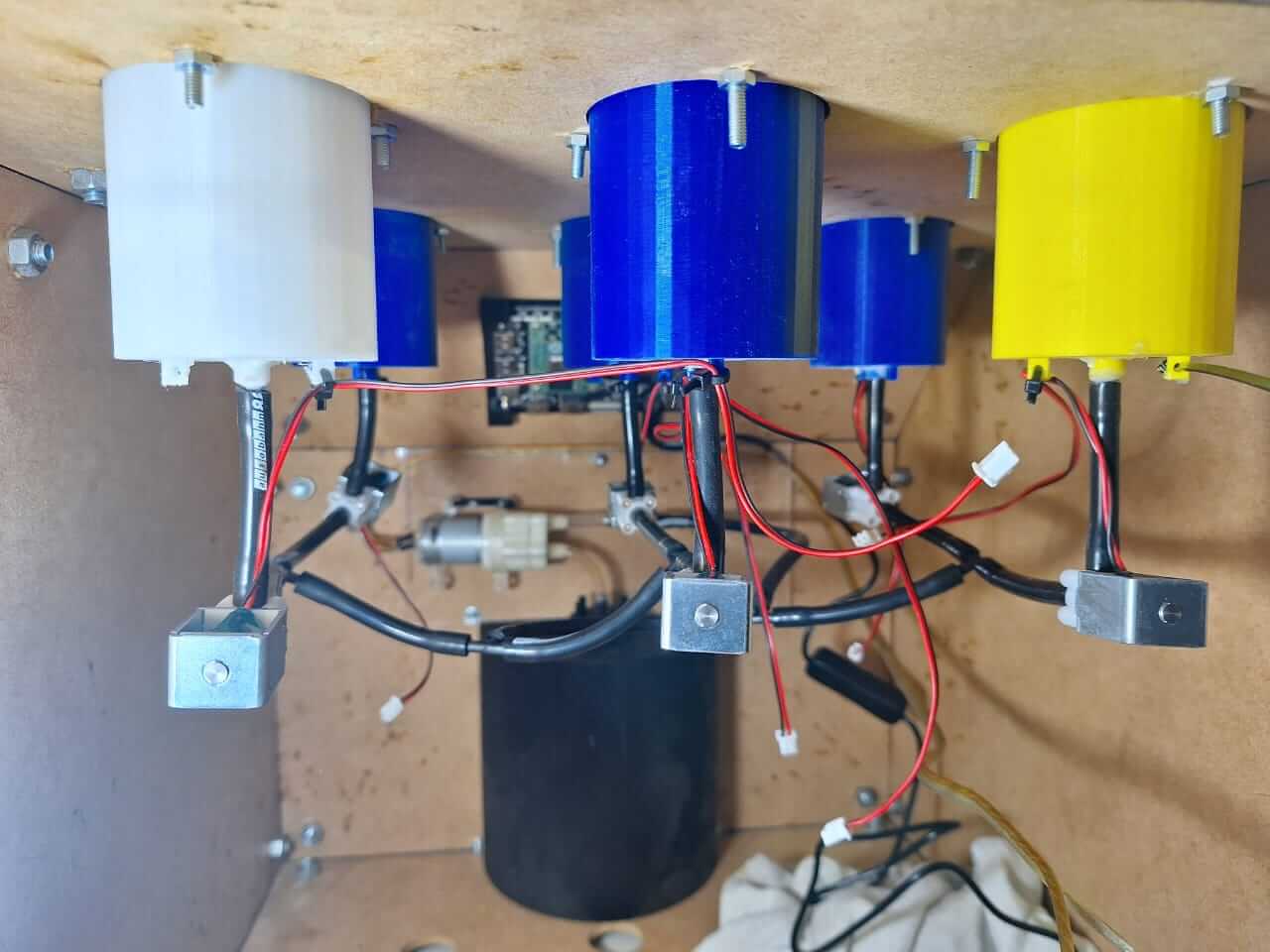
To complete the assembly, I added the hoses and solenoid valves. There are six in total, all connected together and leading to the extruder I 3D printed, which is located at the top of the cup holder.
The last step was testing the PCB to see if we could control the solenoid valves with the Raspberry Pi. so, in the next video we can se how the pcb start working.
Results
Tasks Completed
- Final version of the 2D frame design completed and cut.
- Final version of the 3D parts design completed and printed.
- Electronics and electrical assembly completed.
- Hydraulic assembly completed.
- Tested the Raspberry Pi with GPIO and the final version of the PCB.
Tasks Remaind
- I need to test the machine at full capacity.
- Test the machine as a final user.
What has worked and what hasn´t?
The machine is completed and functional, but the interface still needs to be integrated. Currently, I have a basic interface, which is the first iteration working as a dispenser. This allows us to use the machine, test how the system operates, and identify any areas that require improvement.
What questions need to be resolved?
- How can I ensure there are no leaks?
- How can I ensure the liquid flows correctly?
- How can I make the backend run directly at boot start?
What have I learned?
Things I have learned throughout this process include the importance of good design and creating different versions of your parts to avoid wasting time and material. This approach enables you to create parts in fewer iterations and prototype more efficiently.
Programming
At this point the only think left is to test the interface, however I need to let you know the process I used to code everithing.
As you know, I'm using a Raspberry Pi CM4, and to be able to use one, the first thing to do is install Linux, which can be done in a few easy steps.
We need to install the operational system (OS) for this we can use the options that raspberri pi has in their page, so the first we need is a micro SD, this is going to be the same or has the same function as a hard disk unit in a laptop or CPU and to flash the OS I'm goint to use the Raspberry Pi imager, you can find this software free in the raspberri page here is the link : Raspberry Pi Imager
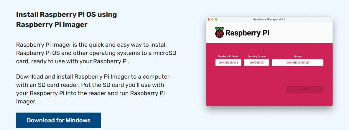
This give you options for MAC, Windows or linux, I'm using windows so ones I download the software and installed we are ready to create the image to use the raspberri pi.
Once it is installed, you need to select the options for the type of Raspberry Pi, the OS, and the memory unit to use.
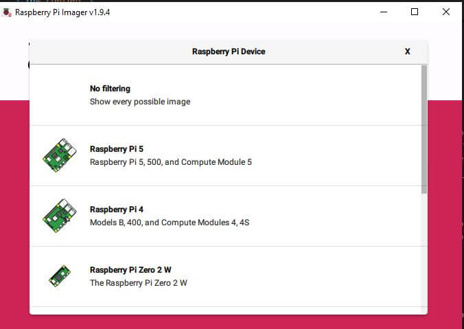
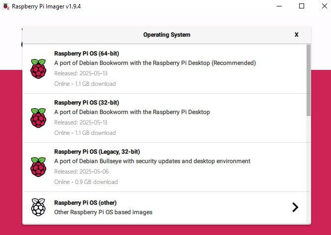
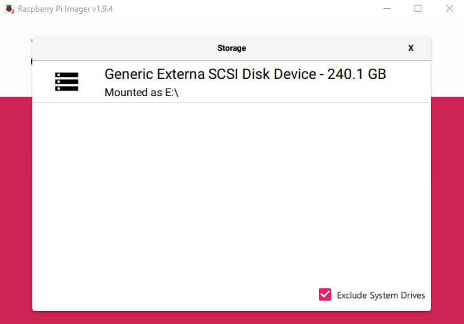
For the final project, I selected Raspberry Pi 4 and Raspberry Pi OS (64-bit), along with a micro SD card. Once everything is set up, you need to click "Next" and follow the steps provided by the software. Wait for the process to complete.

Now that we have the Raspberry Pi ready, we just need to create the program for the interface. I used VS Code to program the interface and then copied the Python file to the Raspberry Pi using a USB drive.
The only issue with using VS Code is that the Raspberry Pi libraries for accessing the GPIO aren't available. However, we can simulate this behavior and then invoke the appropriate library. Let me show you how I handle it.
The following code lets you run the interface on Windows or any OS that supports Python, giving you a preview of how it will look on the Raspberry Pi. This code creates the buttons and also adds a background image to improve the appearance of the interface. It is a simple code that activates the GPIOs of the solenoid valves, and then, with a start button, initiates the whole process.
                        import tkinter as tk
                        from PIL import Image, ImageTk
                        from functools import partial
                        import time

                        # Simulate GPIO on Windows
                        try:
                            import RPi.GPIO as GPIO
                            real_gpio = True
                        except (ImportError, RuntimeError):
                            print("Running in Windows simulation mode.")
                            real_gpio = False

                        class GPIOFake:
                            BCM = OUT = HIGH = LOW = None
                            def setmode(self, *args): pass
                            def setup(self, *args): pass
                            def output(self, pin, value):
                                print(f"[SIMULATED] GPIO {pin} -> {'ON' if value else 'OFF'}")
                            def cleanup(self): pass

                        if not real_gpio:
                            GPIO = GPIOFake()

                        # GPIO pin mapping
                        PINS = {
                            "B1": 14,  # bottle 1
                            "B2": 15,  # bottle 2
                            "B3": 18,  # bottle 3
                            "B4": 17,  # bottle 4
                            "B5": 27,  # bottle 5
                            "B6": 22,  # bottle 6
                            "PUMP": 25 # pump
                        }

                        # States and button references
                        state = {key: False for key in PINS}
                        buttons = {}

                        # Setup GPIO
                        GPIO.setmode(GPIO.BCM)
                        for pin in PINS.values():
                            GPIO.setup(pin, GPIO.OUT)

                        # Functions
                        def button_touch(pin_key):
                            pin = PINS[pin_key]
                            if state[pin_key]:
                                GPIO.output(pin, False)
                                state[pin_key] = False
                                buttons[pin_key].config(bg="#cc3300")  # OFF = red
                            else:
                                GPIO.output(pin, True)
                                state[pin_key] = True
                                buttons[pin_key].config(bg="#00cc66")  # ON = green

                        def pump(pin_key):
                            pump_pin = PINS[pin_key]
                            GPIO.output(pump_pin, True)
                            time.sleep(5)
                            # Reset all outputs and states
                            for key, pin in PINS.items():
                                GPIO.output(pin, False)
                                state[key] = False
                                if key in buttons:
                                    buttons[key].config(bg="#cc3300")  # reset to OFF/red

                        # Create main window
                        window = tk.Tk()
                        window.title("GPIO CONTROL")
                        window.geometry("600x400")

                        # Load and place background image
                        bg_image = Image.open("C:/Users/oscar/Documents/VS_Code_Projects/background.jpg").resize((600, 400))
                        bg_photo = ImageTk.PhotoImage(bg_image)
                        bg_label = tk.Label(window, image=bg_photo)
                        bg_label.place(x=0, y=0, relwidth=1, relheight=1)

                        # Title
                        title_label = tk.Label(window, text="LET'S MIX", font=("Arial", 24), fg="white", bg="#1e1e1e")
                        title_label.place(relx=0.5, y=20, anchor="n")

                        # Row 1
                        row1 = tk.Frame(window, bg="", bd=0, highlightthickness=0)
                        row1.place(relx=0.5, y=80, anchor="n")

                        buttons["B6"] = tk.Button(row1, text="6", width=10, height=2, font=("Arial", 14),
                                                bg="#cc3300", fg="white", command=partial(button_touch, "B6"))
                        buttons["B6"].pack(side="left", padx=5)

                        buttons["B5"] = tk.Button(row1, text="5", width=10, height=2, font=("Arial", 14),
                                                bg="#cc3300", fg="white", command=partial(button_touch, "B5"))
                        buttons["B5"].pack(side="left", padx=5)

                        buttons["B4"] = tk.Button(row1, text="4", width=10, height=2, font=("Arial", 14),
                                                bg="#cc3300", fg="white", command=partial(button_touch, "B4"))
                        buttons["B4"].pack(side="left", padx=5)

                        # Row 2
                        row2 = tk.Frame(window, bg="", bd=0, highlightthickness=0)
                        row2.place(relx=0.5, y=160, anchor="n")

                        buttons["B3"] = tk.Button(row2, text="3", width=10, height=2, font=("Arial", 14),
                                                bg="#cc3300", fg="white", command=partial(button_touch, "B3"))
                        buttons["B3"].pack(side="left", padx=5)

                        buttons["B2"] = tk.Button(row2, text="2", width=10, height=2, font=("Arial", 14),
                                                bg="#cc3300", fg="white", command=partial(button_touch, "B2"))
                        buttons["B2"].pack(side="left", padx=5)

                        buttons["B1"] = tk.Button(row2, text="1", width=10, height=2, font=("Arial", 14),
                                                bg="#cc3300", fg="white", command=partial(button_touch, "B1"))
                        buttons["B1"].pack(side="left", padx=5)

                        # START button
                        tk.Button(window, text="START", font=("Arial", 16),
                                bg="#444444", fg="white", command=partial(pump, "PUMP")).place(relx=0.5, rely=0.9, anchor="s")

                        # Main loop
                        window.mainloop()

                        # GPIO cleanup
                        if real_gpio:
                            GPIO.cleanup()
Code source: Oscar Repository
The next video shows how the simulation works.
Now that the interface works, it's time to transfer the Python file to the Raspberry Pi and start testing. First, I remove the simulation parts from the code because they are not needed on the Raspberry Pi. However, this step is optional, as the same file works for both cases, but I prefer it without the simulation section.
style> pre code { display: block; background-color: #f5f5f5; padding: 15px; border-radius: 5px; overflow-x: auto; font-family: 'Courier New', Courier, monospace; font-size: 14px; color: #333; line-height: 1.5; border: 1px solid #ddd; }
                        import tkinter as tk
                        from PIL import Image, ImageTk
                        from functools import partial
                        import RPi.GPIO as GPIO

                        # GPIO pin mapping
                        PINS = {
                            "B1": 14,  # bottle 1
                            "B2": 15,  # bottle 2
                            "B3": 18,  # bottle 3
                            "B4": 17,  # bottle 4
                            "B5": 27,  # bottle 5
                            "B6": 22,  # bottle 6
                            "PUMP": 25 # pump
                        }

                        # States and button references
                        state = {key: False for key in PINS}
                        buttons = {}

                        # Setup GPIO
                        GPIO.setmode(GPIO.BCM)
                        for pin in PINS.values():
                            GPIO.setup(pin, GPIO.OUT)

                        # Functions
                        def button_touch(pin_key):
                            pin = PINS[pin_key]
                            if state[pin_key]:
                                GPIO.output(pin, False)
                                state[pin_key] = False
                                buttons[pin_key].config(bg="#cc3300")  # OFF = red
                            else:
                                GPIO.output(pin, True)
                                state[pin_key] = True
                                buttons[pin_key].config(bg="#00cc66")  # ON = green

                        def pump(pin_key):
                            pump_pin = PINS[pin_key]
                            GPIO.output(pump_pin, True)

                            def stop_all():
                                for key, pin in PINS.items():
                                    GPIO.output(pin, False)
                                    state[key] = False
                                    if key in buttons:
                                        buttons[key].config(bg="#cc3300")  # reset to OFF/red

                            window.after(5000, stop_all)  # 5 seconds later

                        # Create main window
                        window = tk.Tk()
                        window.title("GPIO CONTROL")
                        window.geometry("600x400")

                        def exit_fullscreen(event=None):
                            window.attributes("-fullscreen", False)

                        window.bind("", exit_fullscreen)

                        screen_width = window.winfo_screenwidth()
                        screen_height = window.winfo_screenheight()

                        # Load and place background image
                        bg_image = Image.open("background.jpg").resize((screen_width, screen_height))
                        bg_photo = ImageTk.PhotoImage(bg_image)
                        bg_label = tk.Label(window, image=bg_photo)
                        bg_label.place(x=0, y=0, relwidth=1, relheight=1)

                        # Title
                        title_label = tk.Label(window, text="LET'S MIX", font=("Arial", 24), fg="white", bg="#1e1e1e")
                        title_label.place(relx=0.5, y=20, anchor="n")

                        # Row 1
                        row1 = tk.Frame(window, bg="", bd=0, highlightthickness=0)
                        row1.place(relx=0.5, y=80, anchor="n")

                        buttons["B6"] = tk.Button(row1, text="6", width=10, height=2, font=("Arial", 14),
                                                bg="#cc3300", fg="white", command=partial(button_touch, "B6"))
                        buttons["B6"].pack(side="left", padx=5)

                        buttons["B5"] = tk.Button(row1, text="5", width=10, height=2, font=("Arial", 14),
                                                bg="#cc3300", fg="white", command=partial(button_touch, "B5"))
                        buttons["B5"].pack(side="left", padx=5)

                        buttons["B4"] = tk.Button(row1, text="4", width=10, height=2, font=("Arial", 14),
                                                bg="#cc3300", fg="white", command=partial(button_touch, "B4"))
                        buttons["B4"].pack(side="left", padx=5)

                        # Row 2
                        row2 = tk.Frame(window, bg="", bd=0, highlightthickness=0)
                        row2.place(relx=0.5, y=160, anchor="n")

                        buttons["B3"] = tk.Button(row2, text="3", width=10, height=2, font=("Arial", 14),
                                                bg="#cc3300", fg="white", command=partial(button_touch, "B3"))
                        buttons["B3"].pack(side="left", padx=5)

                        buttons["B2"] = tk.Button(row2, text="2", width=10, height=2, font=("Arial", 14),
                                                bg="#cc3300", fg="white", command=partial(button_touch, "B2"))
                        buttons["B2"].pack(side="left", padx=5)

                        buttons["B1"] = tk.Button(row2, text="1", width=10, height=2, font=("Arial", 14),
                                                bg="#cc3300", fg="white", command=partial(button_touch, "B1"))
                        buttons["B1"].pack(side="left", padx=5)

                        # START button
                        tk.Button(window, text="START", font=("Arial", 16),
                                bg="#444444", fg="white", command=partial(pump, "PUMP")).place(relx=0.5, rely=0.9, anchor="s")

                        # Main loop
                        window.mainloop()

                        # GPIO cleanup
                        GPIO.cleanup()
Code source: Oscar Repository
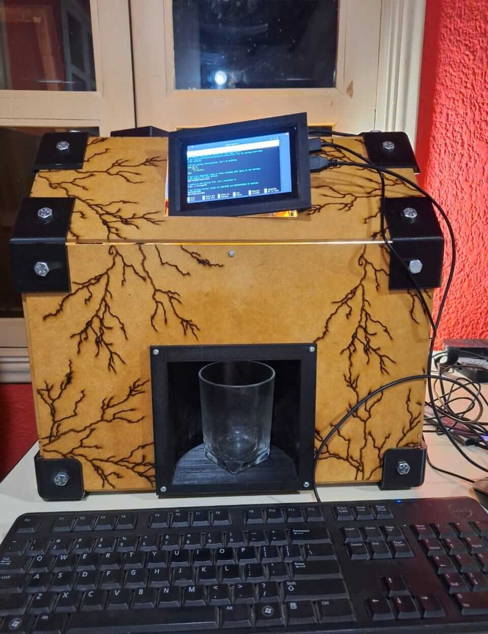
Now that we have the Raspberry Pi with the Python file, we can run it and test how it works by turning on the solenoid valves. You can see the testing process in the next videos.
The interface works the same as in the simulation. Now, let's see how it interacts with the PCB.
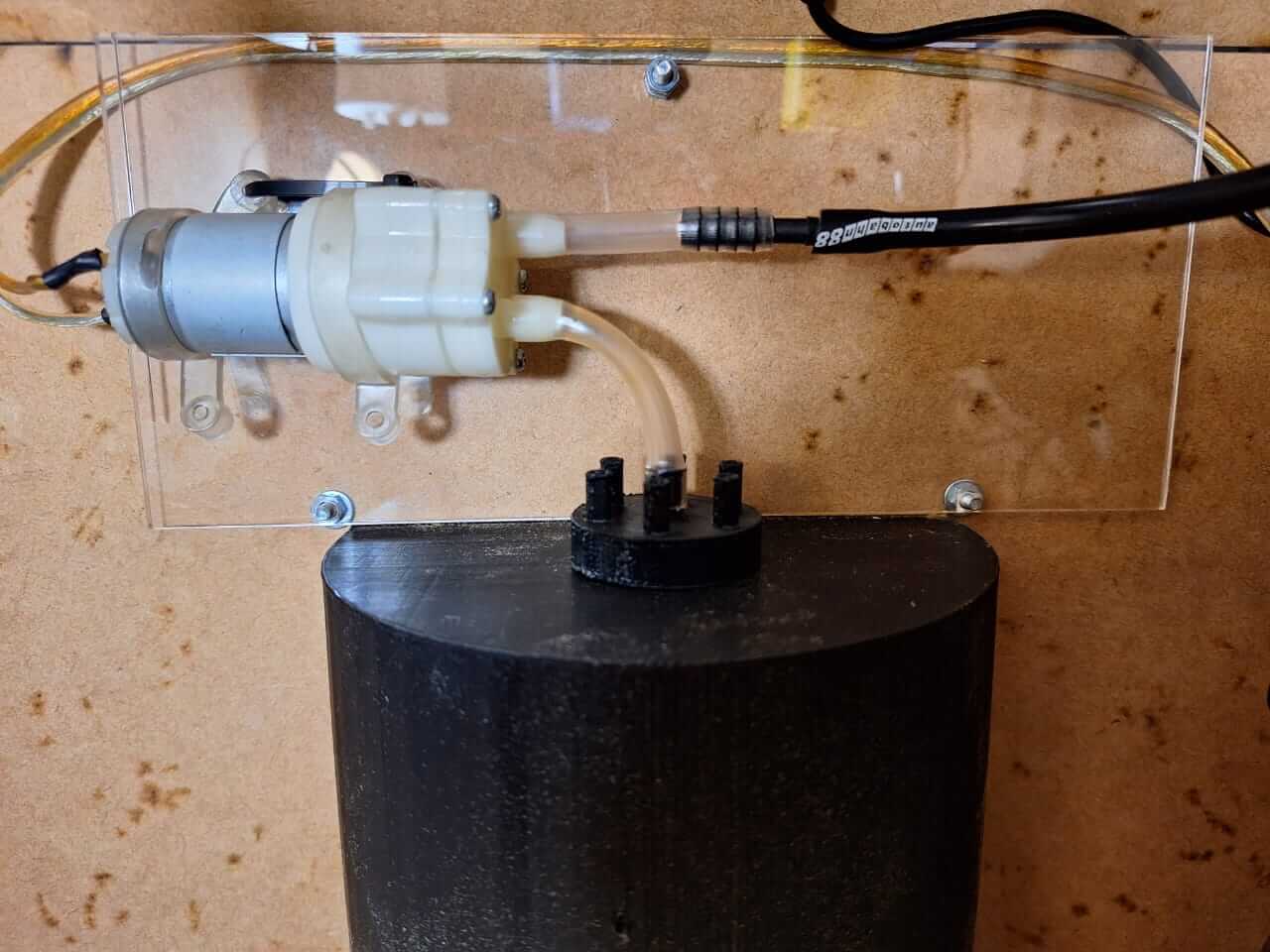
It works; however, after testing a little bit with water, I noticed that the liquid doesn't flow as fast as I expected. To fix this issue, I added a small pump to create a vacuum in the system. The "START" button in the previous code can now turn the pump on. In the next image, you can see the pump installed, which is controlled with a one channel relay module.
Let's see the whole process working with the pump improvement and the final Result.
Issues
All the issues I encountered were related to 3D printing, such as power outages that required restarting the printing process. Additionally, the filament got stuck in the extruder, causing it to stop extruding material, which resulted in lost layers and failed prints. Lastly, one of the bottle holders failed to adhere to the print bed at the start, leading to a failed print.
Another issue is leaking. After using the machine for a while, I started noticing liquid leaking from the connections between the bottle holder and the solenoid valves. I realized that 3D printing is not the best option for holding liquids, so in the future I will change those parts or maybe apply a treatment to avoid leaking. I need to research and compare solutions.
Next Steps
For this project, the next steps I want to include are adding larger solenoid valves and hoses with a bigger interior diameter to increase the liquid flow. Additionally, I plan to include different screens in the interface to create an intuitive user experience and connect the cocktail database to the backend so the screen can display multiple options based on the bottles placed on top.
Presentation
Final Project Files links
In the next links, you can download the files for the assignments.
- Final Project Schedule
- Bottle holder Solidworks
- Bottle holder STL
- Cup holder Solidworks
- Cup holder STL
- Extruder Solidworks
- Extruder STL
- Join 90 edge Solidworks
- Join 90 edge STL
- Join 90 degrees Solidworks
- Join 90 degrees STL
- Join 135 degrees Solidworks
- Join 135 degrees STL
- Join 135 degrees mirror Solidworks
- Join 135 degrees mirror STL
- Screen Holder Solidworks
- Screen Holder STL
- PCB Fusion 360 complete project
- Python files Interface Simulation and Raspberry Pi