
Week 10
Introduction
This page outlines the steps followed during week 10 of the Fab Academy assignments.
The tasks for this week involved Output Devices and the following assignments:
- Measure the power consumption of an output device
- Add an output device to a microcontroller board you've designed, and program it to do something
group assignment:
Individual assignment:
Let's start.....................

Assignments
Output Device
The output devices are the devices that allow us to interact with the microcontroller. The output devices are the devices that allow us to control the microcontroller and the input devices are the devices that allow us to read the signals from the microcontroller.
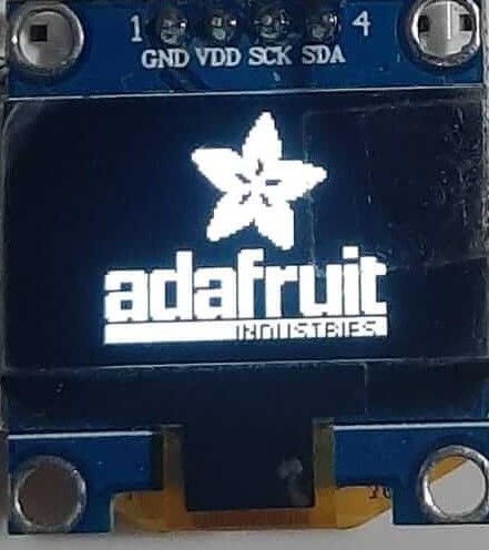
The output device we are going to use is the OLED display. The OLED display is a very useful tool that allows us to display the information from the microcontroller.
The OLED display is a GM009605 display that has a resolution of 128x64 pixels. This specific display uses the I2C protocol to communicate with the microcontroller. The I2C protocol is a two-wire protocol that allows us to communicate with the microcontroller.
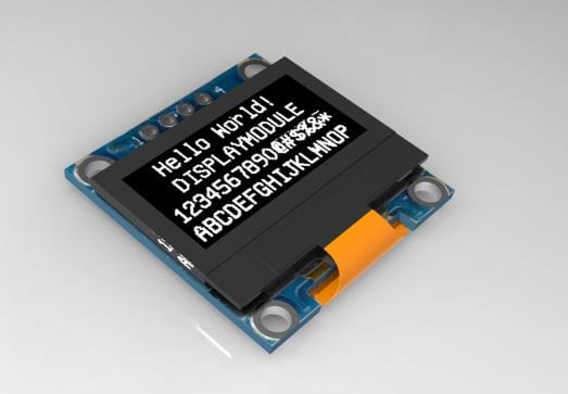
Image source OLED Display
Understanding I2C Protocol
I2C (Inter-Integrated Circuit) is a widely used communication protocol in embedded systems. It allows multiple devices to communicate with a microcontroller using just two wires: SDA (Serial Data Line) and SCL (Serial Clock Line). This makes it ideal for connecting sensors, displays, and other peripherals in a compact and efficient manner.
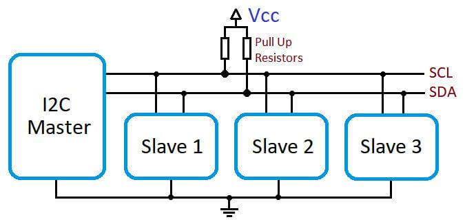
Image source I2C Protocol
Key Features of I2C
- Two-Wire Communication: Only two lines are required for communication: SDA for data and SCL for the clock signal.
- Master-Slave Architecture: One device acts as the master (e.g., ESP32), while others act as slaves (e.g., sensors like ADXL343).
- Addressing: Each slave device has a unique 7-bit or 10-bit address, allowing the master to communicate with specific devices.
- Multi-Master Support: Although uncommon, I2C supports multiple masters on the same bus.
- Acknowledgment: After each byte of data is sent, the receiver sends an acknowledgment (ACK) to confirm receipt.
How I2C Works
- Start Condition: The master initiates communication by pulling the SDA line low while the SCL line remains high.
- Addressing: The master sends the 7-bit address of the target slave device, followed by a read/write bit.
- Acknowledgment: The slave device responds with an ACK if it recognizes its address.
- Data Transfer: Data is transferred in 8-bit packets, with the receiver sending an ACK after each byte.
- Stop Condition: The master ends communication by releasing the SDA line while the SCL line is high.
Device Addressing
Each I2C device has a unique 7-bit or 10-bit address. For example, the ADXL343 accelerometer typically uses the address 0x53 or 0x1D, depending on the configuration of its address pin. The address is sent by the master during the addressing phase, allowing the slave to recognize and respond to the communication.
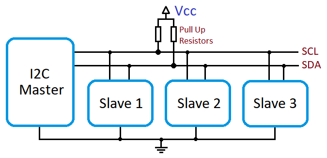
Pull-Up Resistors
I2C lines (SDA and SCL) require pull-up resistors to ensure proper operation. These resistors pull the lines high when no device is actively driving them low. Typical values range from 4.7kΩ to 10kΩ, depending on the bus speed and capacitance.
Advantages of I2C
- Simple and efficient communication with multiple devices.
- Requires only two wires, reducing complexity and cost.
- Supports a wide range of devices and peripherals.
Limitations of I2C
- Limited speed compared to other protocols like SPI.
- Shorter communication distance due to signal degradation.
- Requires careful management of device addresses to avoid conflicts.
Understanding the I2C protocol is essential for working with modern microcontrollers and peripherals. By mastering its principles, you can efficiently integrate a wide variety of devices into your projects.
The next step is to connect the OLED display to the ESP32. The OLED display has four pins: VCC, GND, SDA and SCL. The VCC pin is connected to the 3.3V pin of the ESP32, the GND pin is connected to the GND pin of the ESP32, the SDA pin is connected to the GPIO21 pin of the ESP32 and the SCL pin is connected to the GPIO22 pin of the ESP32. But this can change depending on the board you are using. The following image shows the connections of the OLED display.

Image source: Own Design
To code the ESP32 we are going to use VSCode and PlatformIO. The code is going to be written in C++ and we are going to use the Adafruit library to control the OLED display. The Adafruit library is a library that allows us to control the OLED display using the I2C protocol. The library is very easy to use and allows us to control the OLED display with just a few lines of code.
we are going to use the following code to control the OLED display:
                        #include "Wire.h"
                        #include "Adafruit_GFX.h"
                        #include "Adafruit_SSD1306.h"

                        #define SDA_PIN 5 // SDA pin for ESP32
                         #define SCL_PIN 6 // SCL pin for ESP32

                        #define SCREEN_WIDTH 128 // OLED display width, in pixels
                        #define SCREEN_HEIGHT 64 // OLED display height, in pixels

                        #define OLED_RESET     -1 // Reset pin # (or -1 if sharing Arduino reset pin)
                        #define SCREEN_ADDRESS 0x3C ///< See datasheet for Address; 0x3D for 128x64, 0x3C for 128x32
                        Adafruit_SSD1306 display(SCREEN_WIDTH, SCREEN_HEIGHT, &Wire, OLED_RESET);

                        #define NUMFLAKES     10 // Number of snowflakes in the animation example

                        #define LOGO_HEIGHT   16
                        #define LOGO_WIDTH    16
                        static const unsigned char PROGMEM logo_bmp[] =
                        { 0b00000000, 0b11000000,
                          0b00000001, 0b11000000,
                          0b00000001, 0b11000000,
                          0b00000011, 0b11100000,
                          0b11110011, 0b11100000,
                          0b11111110, 0b11111000,
                          0b01111110, 0b11111111,
                          0b00110011, 0b10011111,
                          0b00011111, 0b11111100,
                          0b00001101, 0b01110000,
                          0b00011011, 0b10100000,
                          0b00111111, 0b11100000,
                          0b00111111, 0b11110000,
                          0b01111100, 0b11110000,
                          0b01110000, 0b01110000,
                          0b00000000, 0b00110000 };


                       void testdrawstyles(void) {
                         display.clearDisplay();

                         display.setTextSize(1);             // Normal 1:1 pixel scale
                         display.setTextColor(SSD1306_WHITE);        // Draw white text
                         display.setCursor(0,0);             // Start at top-left corner
                         display.println(F("Hello, world!"));

                         display.setTextColor(SSD1306_BLACK, SSD1306_WHITE); // Draw 'inverse' text
                         display.println(3.141592);

                         display.setTextSize(2);             // Draw 2X-scale text
                         display.setTextColor(SSD1306_WHITE);
                         display.print(F("0x")); display.println(0xDEADBEEF, HEX);

                         display.display();
                         delay(2000);
                       }


                       void testdrawbitmap(void) {
                         display.clearDisplay();

                         display.drawBitmap(
                           (display.width()  - LOGO_WIDTH ) / 2,
                           (display.height() - LOGO_HEIGHT) / 2,
                           logo_bmp, LOGO_WIDTH, LOGO_HEIGHT, 1);
                         display.display();
                         delay(1000);
                       }

                       #define XPOS   0 // Indexes into the 'icons' array in function below
                       #define YPOS   1
                       #define DELTAY 2

                       void testanimate(const uint8_t *bitmap, uint8_t w, uint8_t h) {
                         int8_t f, icons[NUMFLAKES][3];

                         // Initialize 'snowflake' positions
                         for(f=0; f< NUMFLAKES; f++) {
                           icons[f][XPOS]   = random(1 - LOGO_WIDTH, display.width());
                           icons[f][YPOS]   = -LOGO_HEIGHT;
                           icons[f][DELTAY] = random(1, 6);
                           Serial.print(F("x: "));
                           Serial.print(icons[f][XPOS], DEC);
                           Serial.print(F(" y: "));
                           Serial.print(icons[f][YPOS], DEC);
                           Serial.print(F(" dy: "));
                           Serial.println(icons[f][DELTAY], DEC);
                         }

                         for(;;) { // Loop forever...
                           display.clearDisplay(); // Clear the display buffer

                           // Draw each snowflake:
                           for(f=0; f< NUMFLAKES; f++) {
                             display.drawBitmap(icons[f][XPOS], icons[f][YPOS], bitmap, w, h, SSD1306_WHITE);
                           }

                           display.display(); // Show the display buffer on the screen
                           delay(200);        // Pause for 1/10 second

                           // Then update coordinates of each flake...
                           for(f=0; f< NUMFLAKES; f++) {
                             icons[f][YPOS] += icons[f][DELTAY];
                             // If snowflake is off the bottom of the screen...
                             if (icons[f][YPOS] >= display.height()) {
                               // Reinitialize to a random position, just off the top
                               icons[f][XPOS]   = random(1 - LOGO_WIDTH, display.width());
                               icons[f][YPOS]   = -LOGO_HEIGHT;
                               icons[f][DELTAY] = random(1, 6);
                             }
                           }
                         }
                       }

                        void setup() {
                          Serial.begin(115200);

                          Wire.begin(SDA_PIN, SCL_PIN); // Initialize I2C with specified SDA and SCL pins

                         // I2C Scanner
                         Serial.println(F("Scanning for I2C devices..."));
                         byte count = 0;
                         for (byte address = 1; address < 127; address++) {
                           Wire.beginTransmission(address);
                           if (Wire.endTransmission() == 0) {
                            Serial.print(F("Found I2C device at address 0x"));
                            if (address < 16) Serial.print(F("0"));
                            Serial.println(address, HEX);
                            count++;
                           }
                         }
                         if (count == 0) Serial.println(F("No I2C devices found."));
                         else Serial.print(F("Found ")); Serial.print(count); Serial.println(F(" device(s)."));

                          // SSD1306_SWITCHCAPVCC = generate display voltage from 3.3V internally
                          if(!display.begin(SSD1306_SWITCHCAPVCC, SCREEN_ADDRESS)) {
                            Serial.println(F("SSD1306 allocation failed"));
                            for(;;); // Don't proceed, loop forever
                          }

                          display.display();
                          delay(2000); // Pause for 2 seconds

                          // Clear the buffer
                          display.clearDisplay();

                          // Draw a single pixel in white
                          display.drawPixel(10, 10, SSD1306_WHITE);

                          display.display();
                          delay(2000);

                          testdrawstyles();    // Draw 'stylized' characters

                          testdrawbitmap();    // Draw a small bitmap image

                          // Invert and restore display, pausing in-between
                          display.invertDisplay(true);
                          delay(1000);
                          display.invertDisplay(false);
                          delay(1000);

                          testanimate(logo_bmp, LOGO_WIDTH, LOGO_HEIGHT); // Animate bitmaps
                        }

                        void loop() {
                        }
Code source: Github Repository
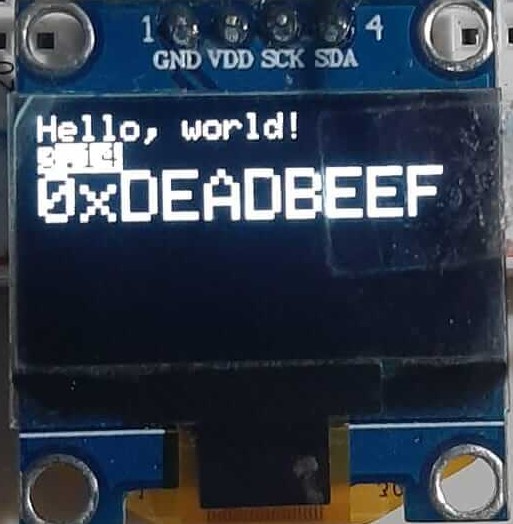
The code is going to generate a bitmap image of the Adafruit logo and the also some text starting with "Hello, world!".
Now that we are capable of controlling the OLED display, we are going to measure the power consumption of the OLED display. This is measured using a multimeter, then is connected in series with the OLED display and set to measure the current in milliamps (mA).
However, in our case, we are going to use a device called Current Ranger to measure the power consumption of the OLED display.
If you want more information about the Current Ranger, you can check the following link: CURRENT RANGER
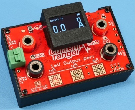
Image source CURRENT RANGER
The Current Ranger is a device that allows us to measure current in milliamps (mA). It is connected in series with the OLED display and configured to measure current in milliamps (mA), similar to how a multimeter operates.
Something we need to take into account is that the Current Ranger is a very sensitive device, so every time the screen changes, the current consumption changes.
In this case we are going to measure the consumption of the OLED display when it is playing the animation.
>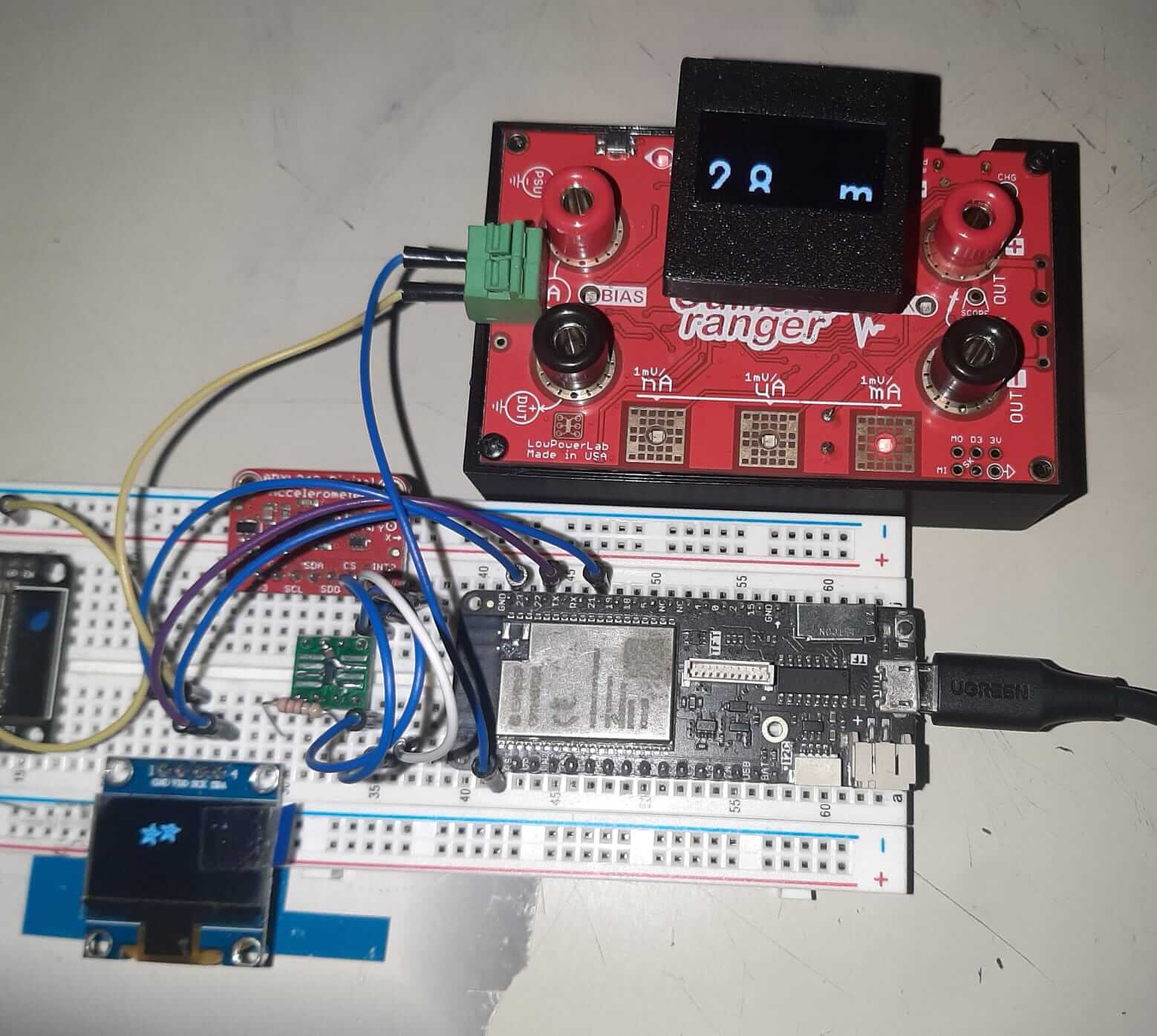
In this case the current consumption is between 1.2mA and 14.4mA, depending on the brightness of the OLED display. The OLED display is a very low power consumption device, which makes it ideal for battery powered devices.
We use a breadboard to connect the OLED display and the Current Ranger. Just for testing purposes and time saving.
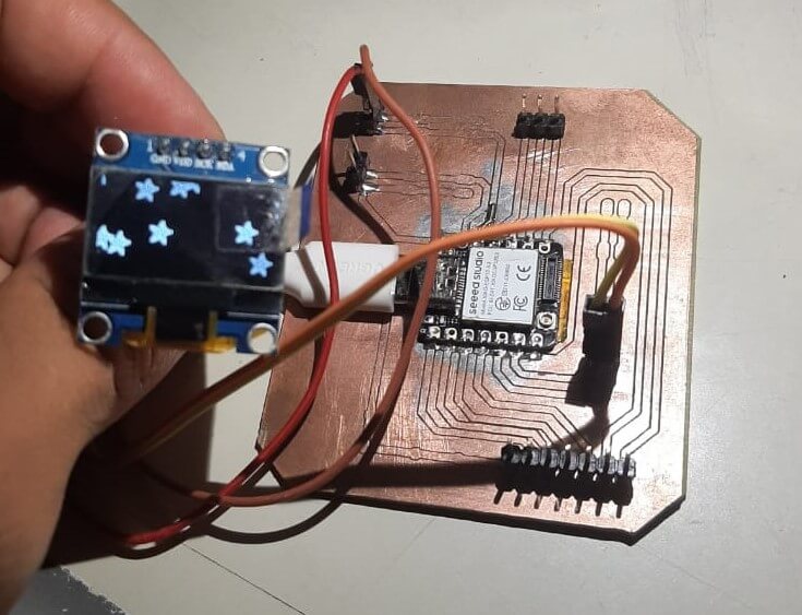
However, in the next image we can se the PCB that we are going to use to connect the OLED display. The PCB is a very simple PCB that we development in the previous weeks. the link to the PCB is:
HERO SHOT
Issues
For this week, we didn't have any issues with the assignments, because I had experience working with the ESP32 and the OLED Display. However, I have some recommendations for the future:
- Make sure to use the correct pins for the I2C protocol.
- Make sure to use the correct library for the OLED display.
- Make sure to use the correct address for the OLED display.
- Make sure to use the correct power supply for the OLED display.
- Make sure to use the correct pull-up resistors for the I2C protocol.
- Use the oscilloscope to measure the signals and check if they are correct.
- Use the serial monitor to check if the values are correct.
- Use the datasheet of the components to check the values and the connections.
- Use the library documentation to check the functions and the parameters.
- Use the examples of the library to check if the code is correct.
- Use the comments in the code to check if the code is correct.
Conclusion
In this week we learned how to use the OLED display and how to measure the power consumption of the OLED display. We also learned how to use the I2C protocol to communicate with the OLED display. The I2C protocol is a very useful protocol that allows us to communicate with multiple devices using just two wires.
Lessons Learned
- How to use the OLED display
- How to use the I2C protocol
- How to measure the power consumption of the OLED display
- How to use the Current Ranger
Resources