
Week 11
Introduction
This page outlines the steps followed during week 11 of the Fab Academy assignments.
The tasks for this week involved Network and communication and the following assignments:
- Send a message between two projects.
- Design, build, and connect wired or wireless node(s) with network or bus addresses and local input &/or output device(s).
group assignment:
Individual assignment:
Let's start.....................

Group assignment
Send a message between two projects.
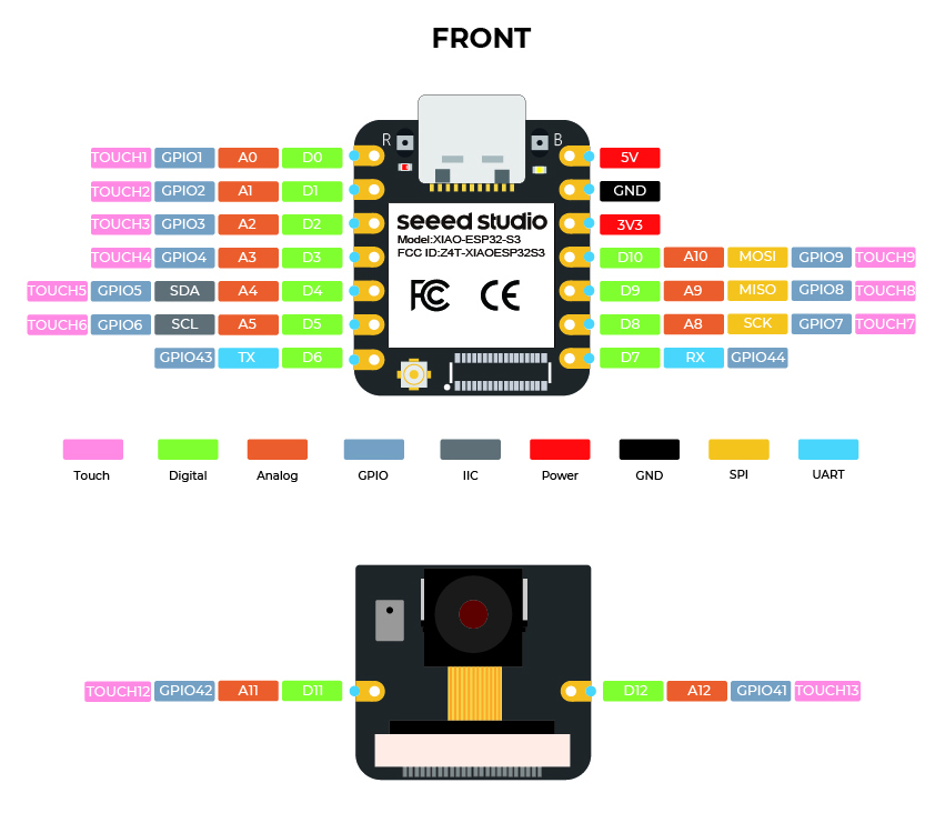
In this week's group assignment, we will explore the concept of network and communication in embedded systems. We will focus on the ESP32 and UART communication between two ESP32 microcontrollers. The ESP32 is a powerful microcontroller with built-in Wi-Fi and Bluetooth capabilities, making it suitable for IoT applications. We will use the ESP32 to send messages between two projects, demonstrating its communication capabilities.
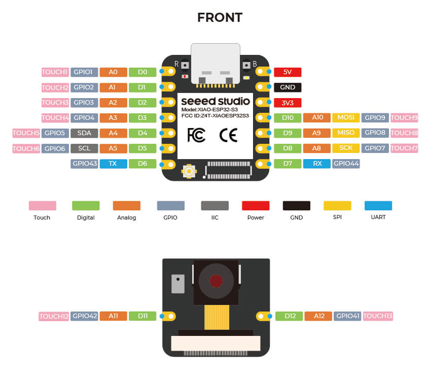
Image source ESP32 S3
UART Communication
A UART (Universal Asynchronous Receiver-Transmitter) is a hardware communication protocol used for serial communication between devices. It allows for the exchange of data between two devices over a serial interface. The UART protocol uses two wires: one for transmitting data (TX) and one for receiving data (RX). The devices communicate by sending and receiving data in the form of bytes, with each byte consisting of 8 bits. The UART protocol is widely used in embedded systems for communication between microcontrollers, sensors, and other devices. It is simple to implement and requires minimal hardware resources.
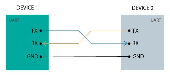
Image source UART
For create a UART communication between two ESP32 microcontrollers, we need to connect the TX pin of one ESP32 to the RX pin of the other ESP32 and vice versa. This allows for bidirectional communication between the two devices. We will use Vs Code with PlatformIO to write the code for the ESP32 microcontrollers. The code will include itializing the UART communication, sending a message from one ESP32 to the other, and receiving the message on the other ESP32. We will also use the Wokwi simulator to ilustrate the UART communication between the two ESP32 microcontrollers.
However, we are going to use a useful feature of the ESP32, which is that we can use any pin to configure the RX and TX pins. Setting the serial channel 2 also let us use the serial monitor to see the data that is being sent and received. This is a great feature of the ESP32, as it allows us to use the serial monitor to debug our code and see the data that is being sent and received.

Image source: Own Design
The code we are going to use can be upload in both to ilustrate how they can send and receive messages between them, even if is the same data, one esp32 will send the data and the other one will receive it, then the other way around.
The code is the following:
                        #include "Arduino.h"
                        uint8_t tries=0; // Initialize tries variable
                        uint8_t Id=0; // Initialize Id variable

                        uint8_t RX_pin=8; // RX pin for Serial2
                        uint8_t TX_pin=7; // TX pin for Serial2

                        void setup() {
                        Serial.begin(115200); // Initialize Serial Monitor at 115200 baud rate
                        Serial2.begin(115200,SERIAL_8N1,RX_pin,TX_pin); // Initialize Serial
                        delay(1000); // Wait for 1 second
                        }

                        void loop() {
                        if (Serial2.available()&&Id!=0){ // Check if data is available to read
                            uint8_t received = Serial2.readStringUntil('\n').toInt(); // Read the data until newline and convert to integer
                            if(received==255){ // Check if received data is greater than or equal to 255
                            received=1; // Reset to 0
                            }else{
                            received++; // Increment
                            }
                            delay(1000); // Wait for 1 second
                            Serial2.println(received); // Send the data as a character to the Serial Monitor
                            Serial2.readStringUntil('\n'); // Read the data until newline
                            delay(500);
                            Serial.println(received); // Print the data to the Serial Monitor
                        }else{
                            if(tries<5){ // Check if tries is less than 5
                            delay(1000); // Wait for 1 second
                            Serial2.println(Id); // Print message if no data is available
                            Serial2.readStringUntil('\n'); // Read the data until newline
                            delay(500);
                            Serial.println(Id);
                            tries++; // Increment tries
                            Id=1;
                            }
                        }
                        }
Code source: Github Repository
Now that we can send and receive messages between the two ESP32 microcontrollers, we can proceed to the next step of the assignment. We will create a more complex structure to send and receive messages. This will allow us to send more data between the two ESP32 microcontrollers.
The purpose of this is to use the same projects from weeks 9 and 10. In week 9, we created a project with an accelerometer, and in week 10, we created a project with an OLED display. We are going to send the data from the accelerometer to the OLED display. This will allow us to see the data from the accelerometer on the OLED display. This is a great way to demonstrate the capabilities of the ESP32 microcontroller and UART communication.
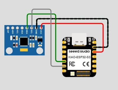
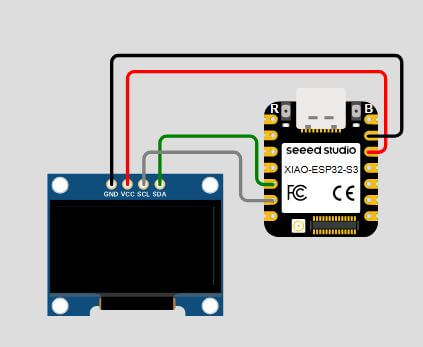
Image source: Own Design
We created a small illustration of how the project looks using the Wokwi simulator. This allows us to see how the project works before building it in real life.
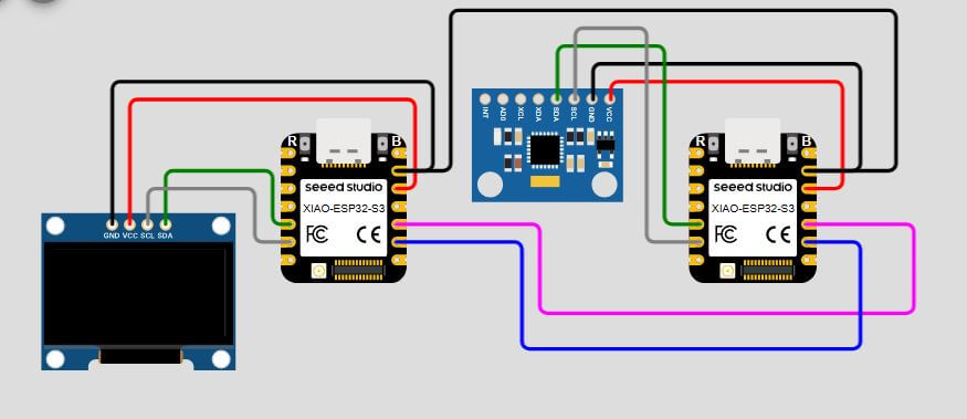
Image source: Own Design
Ones we have the project ready, we can proceed to build it in real life. We connect the TX pin of one ESP32 to the RX pin of the other ESP32 and vice versa. Remember that we can use any pin to configure the RX and TX pins. Also we add the UART communication code to both projects. This allows us to send and receive messages between the two ESP32 microcontrollers.
The code for the accelerometer with the UART modifications is the following:
                        #include "Wire.h"
                        #include "Adafruit_Sensor.h"
                        #include "Adafruit_ADXL343.h"

                        #define SDA_PIN 5 // SDA pin for ESP32
                        #define SCL_PIN 6 // SCL pin for ESP32

                        #define RXD_PIN 8 // RXD pin for ESP32
                        #define TXD_PIN 7 // TXD pin for ESP32

                        Adafruit_ADXL343 accel1 = Adafruit_ADXL343(12345);

                        struct SensorData {
                        float x;
                        float y;
                        float z;
                        };
                        SensorData sensorData;

                        void setup(void)
                        {
                        Serial.begin(115200);
                        Serial2.begin(115200, SERIAL_8N1, RXD_PIN, TXD_PIN); // Initialize Serial2 with custom RX and TX pins
                        while (!Serial);

                        Wire.begin(SDA_PIN, SCL_PIN); // Initialize I2C with custom SDA and SCL pins

                        // I2C Scanner
                        Serial.println("Scanning for I2C devices...");
                        byte count = 0;
                        for (byte address = 1; address < 127; address++) {
                            Wire.beginTransmission(address);
                            if (Wire.endTransmission() == 0) {
                            Serial.print("Found I2C device at address 0x");
                            if (address < 16) Serial.print("0");
                            Serial.println(address, HEX);
                            count++;
                            }
                        }
                        if (count == 0) {
                            Serial.println("No I2C devices found.");
                        } else {
                            Serial.print("Found ");
                            Serial.print(count);
                            Serial.println(" I2C devices.");
                        }
                        Serial.println("");

                        /* Initialise the first sensors, this uses the default address */
                        if(!accel1.begin(0x53))
                        {
                            /* There was a problem detecting the ADXL343 ... check your connections */
                            Serial.println("Ooops, no ADXL343 nr1 detected ... Check your wiring!");
                            while(1);
                        }

                        /* Set the range and data rate to whatever is appropriate for your project */
                        /* See the sensortest example for more details */
                        accel1.setRange(ADXL343_RANGE_2_G);

                        accel1.setDataRate(ADXL343_DATARATE_1600_HZ);

                        /* Display some basic information on these sensors */
                        accel1.printSensorDetails();
                        Serial.println("");
                        }

                        void loop(void)
                        {
                        /* Get new sensor events */
                        sensors_event_t event1;
                        accel1.getEvent(&event1);

                        /* Display the results (acceleration is measured in m/s^2) */
                        Serial.print("X: ");Serial.print(event1.acceleration.x); Serial.print(", ");
                        Serial.print("Y: ");Serial.print(event1.acceleration.y); Serial.print(", ");
                        Serial.print("Z: ");Serial.print(event1.acceleration.z); Serial.println(".");
                        sensorData.x = event1.acceleration.x;
                        sensorData.y = event1.acceleration.y;
                        sensorData.z = event1.acceleration.z;

                        Serial2.write((uint8_t*)&sensorData, sizeof(sensorData)); // Send sensor data to Serial2
                        Serial2.flush(); // Ensure all data is sent before continuing
                        delay(500);
                        }
Code source: Github Repository
The code for the OLED display with the UART modifications is the following:
                        #include "Wire.h"
                        #include "Adafruit_GFX.h"
                        #include "Adafruit_SSD1306.h"

                        #define SDA_PIN 5 // SDA pin for ESP32
                        #define SCL_PIN 6 // SCL pin for ESP32

                        #define RXD_PIN 8 // RXD pin for ESP32
                        #define TXD_PIN 7 // TXD pin for ESP32

                        struct SensorData {
                        float x;
                        float y;
                        float z;
                        };
                        SensorData sensorData;

                        #define SCREEN_WIDTH 128 // OLED display width, in pixels
                        #define SCREEN_HEIGHT 64 // OLED display height, in pixels

                        #define OLED_RESET     -1 // Reset pin # (or -1 if sharing Arduino reset pin)
                        #define SCREEN_ADDRESS 0x3C ///< See datasheet for Address; 0x3D for 128x64, 0x3C for 128x32
                        Adafruit_SSD1306 display(SCREEN_WIDTH, SCREEN_HEIGHT, &Wire, OLED_RESET);

                        #define NUMFLAKES     10 // Number of snowflakes in the animation example

                        #define LOGO_HEIGHT   16
                        #define LOGO_WIDTH    16

                        void drawinfo(void) {
                        display.clearDisplay();

                        display.setTextSize(1);
                        display.setTextColor(SSD1306_WHITE);        // Draw white text
                        display.setCursor(0,0);             // Start at top-left corner
                        display.println(F("Hello Fab Academy!"));
                        display.println(F("Sensor Data:"));
                        display.print(F("X: ")); display.print(sensorData.x); display.println(F(" m/s^2"));
                        display.print(F("Y: ")); display.print(sensorData.y); display.println(F(" m/s^2"));
                        display.print(F("Z: ")); display.print(sensorData.z); display.println(F(" m/s^2"));
                        display.display();
                        }

                        void setup() {
                        Serial.begin(115200);
                        Serial2.begin(115200, SERIAL_8N1, RXD_PIN, TXD_PIN); // Initialize Serial2 with RXD and TXD pins

                        Wire.begin(SDA_PIN, SCL_PIN); // Initialize I2C with specified SDA and SCL pins

                        // I2C Scanner
                        Serial.println(F("Scanning for I2C devices..."));
                        byte count = 0;
                        for (byte address = 1; address < 127; address++) {
                        Wire.beginTransmission(address);
                        if (Wire.endTransmission() == 0) {
                            Serial.print(F("Found I2C device at address 0x"));
                            if (address < 16) Serial.print(F("0"));
                            Serial.println(address, HEX);
                            count++;
                        }
                        }
                        if (count == 0) Serial.println(F("No I2C devices found."));
                        else Serial.print(F("Found ")); Serial.print(count); Serial.println(F(" device(s)."));

                        // SSD1306_SWITCHCAPVCC = generate display voltage from 3.3V internally
                        if(!display.begin(SSD1306_SWITCHCAPVCC, SCREEN_ADDRESS)) {
                            Serial.println(F("SSD1306 allocation failed"));
                            for(;;); // Don't proceed, loop forever
                        }

                        drawinfo();
                        }

                        void loop() {
                        if(Serial2.available()){
                            uint8_t data[sizeof(sensorData)];
                            Serial2.readBytes((char*)data, sizeof(sensorData)); // Read the data from Serial2 into the buffer
                            memcpy(&sensorData, data, sizeof(sensorData)); // Copy the buffer into the sensorData struct
                            drawinfo();
                        }else{
                            delay(100);
                        }
                        }
Code source: Github Repository
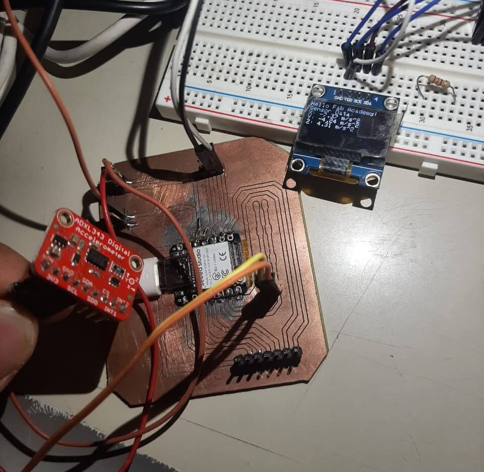
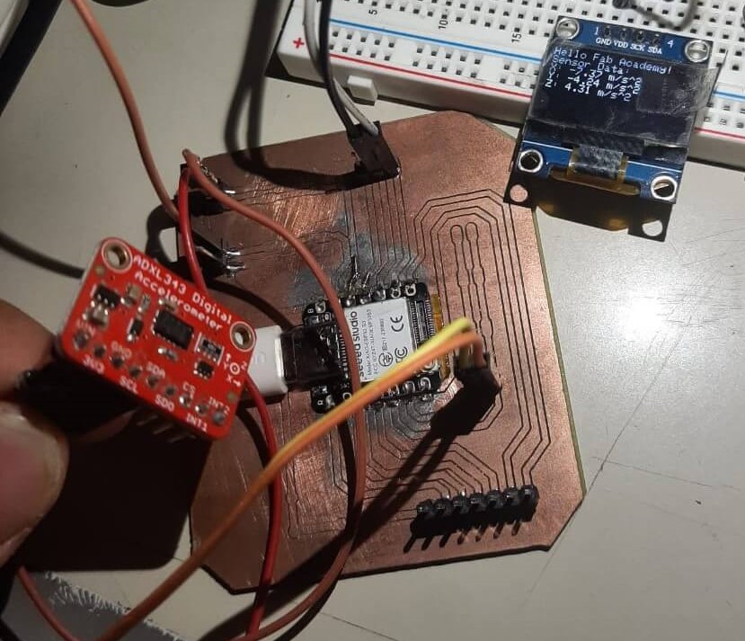
Now that we have the code ready, we can proceed to upload it to the ESP32 microcontrollers. and see how it works in real life. We can see the data from the accelerometer on the OLED display.
Now that have all running, there is something that we can do to test the project a little bit more. A good feature of the ESP32 is that let us use different pins to configure the RX and TX pins. This is a good feature because we can use any pin that we want to use. However, we need to configure the pins in the code. We also create an illustration of how the project looks using the Wokwi simulator. This allows us to see how the project works before building it in real life.
We can conclude that using the UART pins or configuring the RX and TX pins on different pins works perfectly in both cases. The configuration you select will depend on the project you are working on. Additionally, testing with different configurations and scenarios can help identify potential issues and improve the robustness of the system.
Individual assignment
For this assignment, we are going to use the same project as the group assignment. However, we are going to use ESPNOW communication instead of UART communication. ESPNOW is a wireless communication protocol developed by Espressif for their ESP32 microcontrollers.
ESPNOW
ESPNOW is a low-power, low-latency communication protocol that allows for direct communication between ESP32 devices without the need for a Wi-Fi network or router. It uses a peer-to-peer communication model, allowing multiple devices to communicate with each other directly. ESPNOW is ideal for IoT applications where low power consumption and low latency are critical. It is also easy to implement and requires minimal hardware resources.
The ESPNOW protocol uses a unique addressing scheme that allows devices to communicate with each other without the need for a central server or router. Each device has a unique MAC address, which is used to identify the device in the network. The ESPNOW protocol also supports encryption, allowing for secure communication between devices. This is important for IoT applications where security is a concern.
The following image shows the same project as the group assignment, but without the UART Wires to illustrate how the project looks.
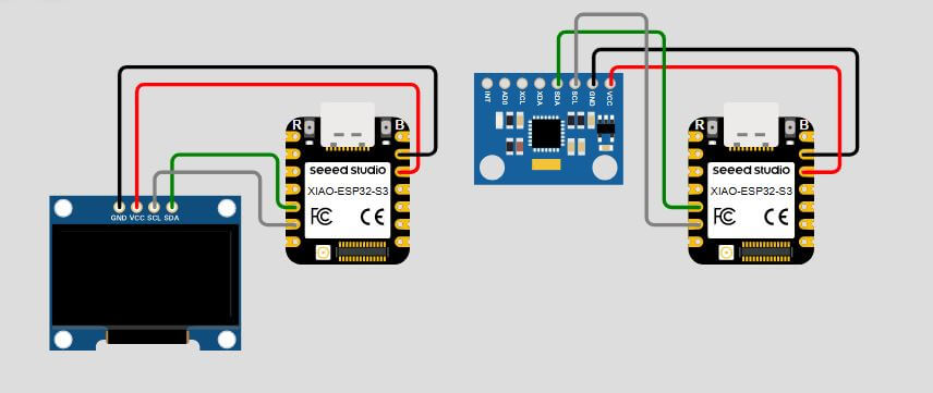
Image source: Own Design
Before addidng the ESPNOW code to the project, we are going to create a small project just to connect two ESP32 to explaind how ESPNOW works.
The code for the ESPNOW communication is the following, we also add comments to the code to explain how it works and what each part of the code does:
                        #include "Arduino.h"
                        #include "WiFi.h"
                        #include "esp_now.h"

                        // MAC address of the other ESP32 device
                        uint8_t otherDeviceMacAddress[] = {0x7C,0x9E,0xBD,0x28,0x82,0x70};
                        //7c:9e:bd:28:82:70 oled {0x7C,0x9E,0xBD,0x28,0x82,0x70};
                        //84:fc:e6:6b:85:58 accel {0x84,0xFC,0xE6,0x6B,0x85,0x58};
                        // Replace with the actual MAC address

                        String msg = "Hello Fab Academy! "; // Message to be sent
                        uint8_t randomId = 0; // Random ID for the message

                        // Callback function to handle received data
                        // This function is called when data is received
                        // It prints the received message to the Serial Monitor
                        void OnDataRecv(const uint8_t * mac, const uint8_t *incomingData, int len) {
                        char msg[len + 1];
                        memcpy(msg, incomingData, len);
                        msg[len] = 0; // Null-terminate the string
                        Serial.print("Received message: ");
                        Serial.println(msg);
                        }

                        // Callback function to handle sent data status
                        // This function is called when the data is sent
                        void OnDataSent(const uint8_t *mac_addr, esp_now_send_status_t status) {
                        Serial.print("Send Status: ");
                        if (status == ESP_NOW_SEND_SUCCESS) {
                            Serial.println("Success");
                        } else {
                            Serial.println("Fail");
                        }
                        }

                        void setup() {
                        Serial.begin(115200); // Initialize Serial Monitor
                        WiFi.mode(WIFI_STA);  // Set WiFi mode to Station (client)

                        randomId = random(0, 255); // Generate a random ID for the message
                        msg += String(randomId); // Append the random ID to the message

                        // Initialize ESP-NOW
                        if (esp_now_init() != ESP_OK) {
                            Serial.println("Error initializing ESP-NOW");
                            return;
                        }

                        // Register peer
                        esp_now_peer_info_t peerInfo;
                        memset(&peerInfo, 0, sizeof(peerInfo));
                        memcpy(peerInfo.peer_addr, otherDeviceMacAddress, 6);
                        peerInfo.channel = 0;
                        peerInfo.encrypt = false;

                        // Add peer
                        if (esp_now_add_peer(&peerInfo) != ESP_OK) {
                            Serial.println("Failed to add peer");
                            return;
                        }

                        // Register for send and receive callbacks
                        esp_now_register_send_cb(OnDataSent);
                        esp_now_register_recv_cb(OnDataRecv);
                        }

                        void loop() {
                        esp_now_send(otherDeviceMacAddress, (uint8_t *)msg.c_str(), msg.length()); // Send message
                        delay(2000); // Wait for 2 seconds
                        }
Code source: Github Repository
Ones we understand how ESPNOW works, we can proceed to add the code to the project.
ESPNOW allows us to create different types of communication, including one-to-one communication, one-to-many communication, and many-to-many communication. Additionally, all these modes can operate in either half-duplex or full-duplex. In this case, we will implement a one-to-one communication in half-duplex setup.
The code for the accelerometer with the ESPNOW modifications is the following:
                        #include "Arduino.h"
                        #include "WiFi.h"
                        #include "esp_now.h"
                        #include "Wire.h"
                        #include "Adafruit_Sensor.h"
                        #include "Adafruit_ADXL343.h"

                        #define SDA_PIN 5 // SDA pin for ESP32
                        #define SCL_PIN 6 // SCL pin for ESP32

                        Adafruit_ADXL343 accel1 = Adafruit_ADXL343(12345);

                        struct SensorData {
                        float x;
                        float y;
                        float z;
                        };
                        SensorData sensorData;

                        // MAC address of the other ESP32 device
                        uint8_t otherDeviceMacAddress[] = {0x7C,0x9E,0xBD,0x28,0x82,0x70};
                        //7c:9e:bd:28:82:70 oled {0x7C,0x9E,0xBD,0x28,0x82,0x70};
                        //84:fc:e6:6b:85:58 accel {0x84,0xFC,0xE6,0x6B,0x85,0x58};
                        // Replace with the actual MAC address

                        // Callback function to handle received data
                        // This function is called when data is received
                        // It prints the received message to the Serial Monitor
                        void OnDataRecv(const uint8_t * mac, const uint8_t *incomingData, int len) {
                        }

                        // Callback function to handle sent data status
                        // This function is called when the data is sent
                        void OnDataSent(const uint8_t *mac_addr, esp_now_send_status_t status) {
                        if (status == ESP_NOW_SEND_SUCCESS) {
                            Serial.print("Data sent successfully  ");
                        } else {
                            Serial.print("Data send failed  ");
                        }
                        }

                        void setup() {
                        Serial.begin(115200); // Initialize Serial Monitor

                        Wire.begin(SDA_PIN, SCL_PIN); // Initialize I2C with custom SDA and SCL pins

                        // I2C Scanner
                        Serial.println("Scanning for I2C devices...");
                        byte count = 0;
                        for (byte address = 1; address < 127; address++) {
                            Wire.beginTransmission(address);
                            if (Wire.endTransmission() == 0) {
                            Serial.print("Found I2C device at address 0x");
                            if (address < 16) Serial.print("0");
                            Serial.println(address, HEX);
                            count++;
                            }
                        }
                        if (count == 0) {
                            Serial.println("No I2C devices found.");
                        } else {
                            Serial.print("Found ");
                            Serial.print(count);
                            Serial.println(" I2C devices.");
                        }
                        Serial.println("");

                        /* Initialise the first sensors, this uses the default address */
                        if(!accel1.begin(0x53))
                        {
                            /* There was a problem detecting the ADXL343 ... check your connections */
                            Serial.println("Ooops, no ADXL343 nr1 detected ... Check your wiring!");
                            while(1);
                        }

                        /* Set the range and data rate to whatever is appropriate for your project */
                        /* See the sensortest example for more details */
                        accel1.setRange(ADXL343_RANGE_2_G);

                        accel1.setDataRate(ADXL343_DATARATE_1600_HZ);

                        /* Display some basic information on these sensors */
                        accel1.printSensorDetails();
                        Serial.println("");

                        WiFi.mode(WIFI_STA);  // Set WiFi mode to Station (client)

                        // Initialize ESP-NOW
                        if (esp_now_init() != ESP_OK) {
                            Serial.println("Error initializing ESP-NOW");
                            return;
                        }

                        // Register peer
                        esp_now_peer_info_t peerInfo;
                        memset(&peerInfo, 0, sizeof(peerInfo));
                        memcpy(peerInfo.peer_addr, otherDeviceMacAddress, 6);
                        peerInfo.channel = 0;
                        peerInfo.encrypt = false;

                        // Add peer
                        if (esp_now_add_peer(&peerInfo) != ESP_OK) {
                            Serial.println("Failed to add peer");
                            return;
                        }

                        // Register for send and receive callbacks
                        esp_now_register_send_cb(OnDataSent);
                        esp_now_register_recv_cb(OnDataRecv);
                        }

                        void loop() {
                        /* Get new sensor events */
                        sensors_event_t event1;
                        accel1.getEvent(&event1);

                        /* Display the results (acceleration is measured in m/s^2) */
                        Serial.print("X: ");Serial.print(event1.acceleration.x); Serial.print(", ");
                        Serial.print("Y: ");Serial.print(event1.acceleration.y); Serial.print(", ");
                        Serial.print("Z: ");Serial.print(event1.acceleration.z); Serial.println(".");
                        sensorData.x = event1.acceleration.x;
                        sensorData.y = event1.acceleration.y;
                        sensorData.z = event1.acceleration.z;

                        esp_now_send(otherDeviceMacAddress, (uint8_t *)&sensorData, sizeof(sensorData)); // Send message
                        delay(500);
                        }
Code source: Github Repository
The code for the OLED display with the ESPNOW modifications is the following:
                        #include "Wire.h"
                        #include "Adafruit_GFX.h"
                        #include "Adafruit_SSD1306.h"
                        #include "Arduino.h"
                        #include "WiFi.h"
                        #include "esp_now.h"

                        #define SDA_PIN 5 // SDA pin for ESP32
                        #define SCL_PIN 6 // SCL pin for ESP32

                        // MAC address of the other ESP32 device
                        uint8_t otherDeviceMacAddress[] = {0x84,0xFC,0xE6,0x6B,0x85,0x58};
                        //7c:9e:bd:28:82:70 oled {0x7C,0x9E,0xBD,0x28,0x82,0x70};
                        //84:fc:e6:6b:85:58 accel {0x84,0xFC,0xE6,0x6B,0x85,0x58};
                        // Replace with the actual MAC address

                        struct SensorData {
                        float x;
                        float y;
                        float z;
                        };
                        SensorData sensorData;

                        #define SCREEN_WIDTH 128 // OLED display width, in pixels
                        #define SCREEN_HEIGHT 64 // OLED display height, in pixels

                        #define OLED_RESET     -1 // Reset pin # (or -1 if sharing Arduino reset pin)
                        #define SCREEN_ADDRESS 0x3C ///< See datasheet for Address; 0x3D for 128x64, 0x3C for 128x32
                        Adafruit_SSD1306 display(SCREEN_WIDTH, SCREEN_HEIGHT, &Wire, OLED_RESET);

                        #define NUMFLAKES     10 // Number of snowflakes in the animation example

                        #define LOGO_HEIGHT   16
                        #define LOGO_WIDTH    16

                        void drawinfo(void) {
                        display.clearDisplay();

                        display.setTextSize(1);
                        display.setTextColor(SSD1306_WHITE);        // Draw white text
                        display.setCursor(0,0);             // Start at top-left corner
                        display.println(F("Hello Fab Academy!"));
                        display.println(F("Sensor Data:"));
                        display.print(F("X: ")); display.print(sensorData.x); display.println(F(" m/s^2"));
                        display.print(F("Y: ")); display.print(sensorData.y); display.println(F(" m/s^2"));
                        display.print(F("Z: ")); display.print(sensorData.z); display.println(F(" m/s^2"));
                        display.display();
                        }

                        // Callback function to handle received data
                        // This function is called when data is received
                        // It prints the received message to the Serial Monitor
                        void OnDataRecv(const uint8_t * mac, const uint8_t *incomingData, int len) {
                            memcpy(&sensorData, incomingData, sizeof(sensorData)); // Copy the buffer into the sensorData struct
                            delay(100);
                        }

                        // Callback function to handle sent data status
                        // This function is called when the data is sent
                        void OnDataSent(const uint8_t *mac_addr, esp_now_send_status_t status) {
                        }

                        void setup() {
                        Serial.begin(115200); // Initialize Serial Monitor

                        Wire.begin(SDA_PIN, SCL_PIN); // Initialize I2C with specified SDA and SCL pins

                        // I2C Scanner
                        Serial.println(F("Scanning for I2C devices..."));
                        byte count = 0;
                        for (byte address = 1; address < 127; address++) {
                            Wire.beginTransmission(address);
                            if (Wire.endTransmission() == 0) {
                            Serial.print(F("Found I2C device at address 0x"));
                            if (address < 16) Serial.print(F("0"));
                            Serial.println(address, HEX);
                            count++;
                            }
                        }
                        if (count == 0) Serial.println(F("No I2C devices found."));
                        else Serial.print(F("Found ")); Serial.print(count); Serial.println(F(" device(s)."));

                        // SSD1306_SWITCHCAPVCC = generate display voltage from 3.3V internally
                        if(!display.begin(SSD1306_SWITCHCAPVCC, SCREEN_ADDRESS)) {
                            Serial.println(F("SSD1306 allocation failed"));
                            for(;;); // Don't proceed, loop forever
                        }

                        drawinfo();

                        WiFi.mode(WIFI_STA);  // Set WiFi mode to Station (client)

                        // Initialize ESP-NOW
                        if (esp_now_init() != ESP_OK) {
                            Serial.println("Error initializing ESP-NOW");
                            return;
                        }

                        // Register peer
                        esp_now_peer_info_t peerInfo;
                        memset(&peerInfo, 0, sizeof(peerInfo));
                        memcpy(peerInfo.peer_addr, otherDeviceMacAddress, 6);
                        peerInfo.channel = 0;
                        peerInfo.encrypt = false;

                        // Add peer
                        if (esp_now_add_peer(&peerInfo) != ESP_OK) {
                            Serial.println("Failed to add peer");
                            return;
                        }

                        // Register for send and receive callbacks
                        esp_now_register_send_cb(OnDataSent);
                        esp_now_register_recv_cb(OnDataRecv);
                        }

                        void loop() {
                        drawinfo();
                        delay(500); // Delay for 1 second
                        }
Code source: Github Repository
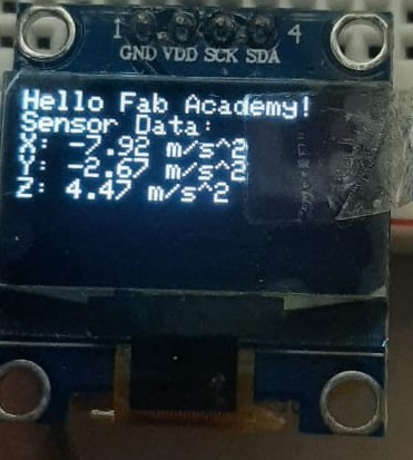
Now that we have the code ready, we can proceed to upload it to the ESP32 microcontrollers. and see how it works in real life. We can see the data from the accelerometer on the OLED display.
We can see how all the data its being sent from the accelerometer to the OLED display like the group assignment, but now we are using ESPNOW communication instead of UART communication. This is a great way to demonstrate the capabilities of the ESP32 microcontroller and ESPNOW communication.
This is helpful for IoT applications where low power consumption and low latency are critical. It is also easy to implement and requires minimal hardware resources.
HERO SHOT
>
Issues
For this week, we didn't have any issues with the assignments, because I had experience working with UART communication and ESPNOW communication, so I was able to complete the assignments without any problems.
However, based on my experience, I can say that the most common issues with UART communication are:
- Incorrect wiring: Make sure that the TX pin of one device is connected to the RX pin of the other device and vice versa.
- Baud rate mismatch: Ensure that both devices are set to the same baud rate for communication.
- Data format mismatch: Check that both devices are using the same data format (e.g., 8N1).
- Noise and interference: Use shielded cables and proper grounding to minimize noise and interference in the communication.
- Buffer overflow: Ensure that the receiving device can handle the incoming data rate to prevent buffer overflow.
- Power supply issues: Make sure that both devices are powered properly and have a stable power supply.
- Software bugs: Check the code for any bugs or errors that may affect communication.
- Debugging tools: Use debugging tools like logic analyzers or oscilloscopes to analyze the communication signals.
In addition, the most common issues with ESPNOW communication are:
- Incorrect MAC address: Ensure that the MAC address of the sender and receiver devices are correct.
- Pairing issues: Make sure that the devices are properly paired before attempting to communicate.
- Interference: Check for any interference from other wireless devices in the area.
- Power supply issues: Ensure that both devices have a stable power supply.
- Software bugs: Check the code for any bugs or errors that may affect communication.
- Debugging tools: Use debugging tools like serial monitors to analyze the communication signals.
- Distance limitations: Ensure that the devices are within range for ESPNOW communication.
- Channel selection: Make sure that both devices are using the same Wi-Fi channel for communication.
- Encryption issues: If using encryption, ensure that both devices are using the same encryption key.
- Data format mismatch: Check that both devices are using the same data format (e.g., byte array).
These issues can be resolved by following the best practices for UART and ESPNOW communication, such as proper wiring, baud rate settings, and debugging techniques.
Project Files links
In the next links, you can download the files for the assignments.
- UART Test Project
- Accelerometer UART Project
- OLED UART Project
- ESPNOW Test Project
- Accelerometer ESPNOW Project
- OLED ESPNOW Project
Conclusion
In conclusion, this week we learned about network and communication in embedded systems. We explored the ESP32 microcontroller and its capabilities for UART and ESPNOW communication. We also learned how to send and receive messages between two ESP32 microcontrollers using both protocols. This knowledge is essential for developing IoT applications and understanding the communication capabilities of embedded systems.
Lessons Learned
- Understanding the basics of UART and ESPNOW communication protocols.
- Learning how to set up and configure UART and ESPNOW communication on ESP32 microcontrollers.
- Exploring the capabilities of the ESP32 microcontroller for IoT applications.
- Understanding the importance of proper wiring, baud rate settings, and debugging techniques in embedded systems.