
Week 15
Introduction
This page outlines the steps followed during week 15 of the Fab Academy assignments.
The tasks for this week involved System Integration and the following assignments:
- Design and document the system integration for your final project.
Assignment:
Let's start.....................

Assignment
The assignment for this week was to design and document the system integration for my final project. I had to consider the hardware components.
I considered the model created in week 2 as the main reference for the following parts. As you can see, this is how it should look.
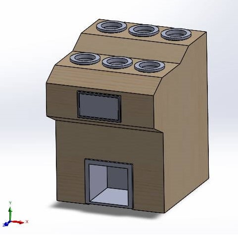
Hardware Components – Smart Bartender
| Component | Description | Fabrication Method |
|---|---|---|
| Wooden Frame | Main structure housing all components | Laser Cut |
| 3D Printed Joints | Connectors for frame stability | 3D Printed |
| Raspberry Pi | Main controller running the UI and automation logic | Purchased |
| Touch Screen | Interface for user interaction | Purchased |
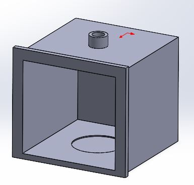
| 3D Printed Screen Frame | Holder/enclosure for the touch screen | 3D Printed |
| 3D Printed Bottle Holders | Secures bottles on the top panel | 3D Printed |
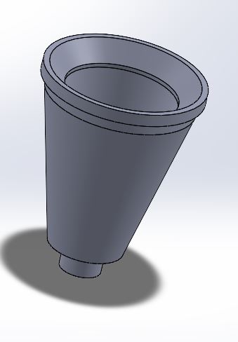
| 3D Printed Cup Base | Base for placing the cup under the dispensing valves | 3D Printed |
| Solenoid Valves | Controls liquid flow from bottles | Purchased |
| Control PCB | Custom PCB to control solenoid valves | Designed & Fabricated |
| Power Supply | Provides power to all electronic components | Purchased |
| DC-DC Regulators | Voltage conversion for components | Purchased |
| Plastic Tubes | Connects bottles to solenoid valves and cup | Purchased |
The components listed above are the main parts of the Smart Bartender system. Each component plays a crucial role in the overall functionality and design of the project. The wooden frame provides the structure, while the 3D printed parts add custom features.
The Raspberry Pi serves as the brain of the system, controlling the touch screen interface and automation logic. The solenoid valves manage the liquid flow, and the custom PCB ensures proper control of these valves. The power supply and DC-DC regulators provide the necessary power to all components. Finally, the plastic tubes connect the bottles to the solenoid valves and the cup, ensuring a seamless dispensing process.
The integration of these components is essential for the successful operation of the Smart Bartender system. Each part must work together harmoniously to create a functional and efficient automated bartending solution.
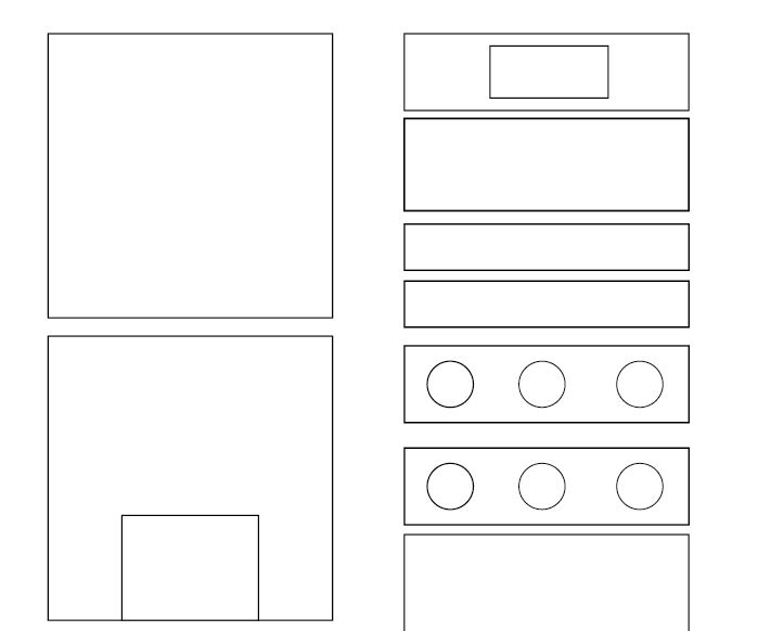
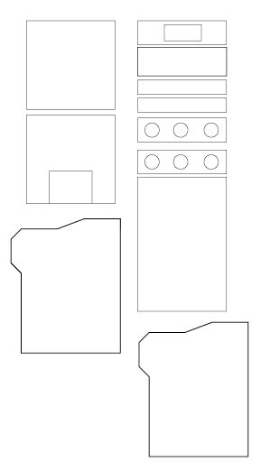
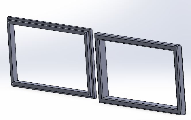
The first Step was to create the wooden frame, which serves as the main structure for the project. The frame is designed to house all the components securely and provide stability during operation. The frame is made from high-quality wood, ensuring durability and strength.
The software used to create the frame is Ilustrator let us create the design and save it as a SVG file.
In the next images, you can see the design of the frame ready to be cut, however before cutting it, I had to make sure that the design was correct and that all the parts fit together properly. To do this, I'm planning create a scaled down version of the frame using cardboard. This will allow me to test the design and make any necessary adjustments before cutting the actual wood.
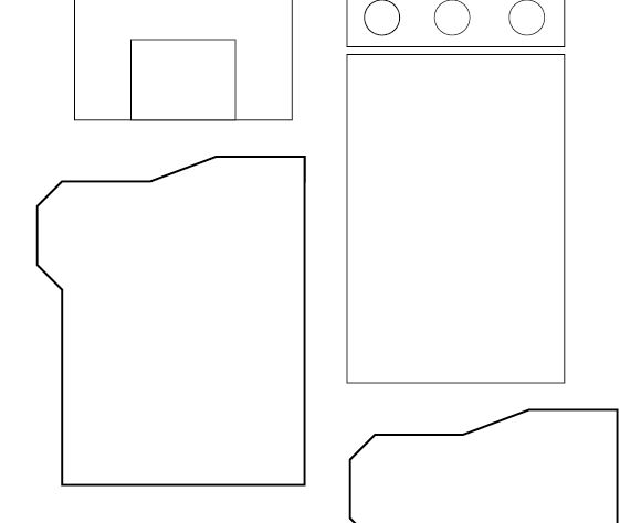
For the 3d printed parts, I used Solidworks to design the components. The 3D printed parts include the joints for the frame, the screen holder, and the bottle holders. These parts are designed to fit perfectly with the wooden frame and provide additional support and functionality.
The 3D printed parts are going to be printed using PLA material, which is known for its strength and durability.
In the next video, you can see the distribution of the frame and the 3D printed parts, providing a preview of how the entire machine will look when assembled.
For the electronics, I used a Raspberry Pi as the main controller for the system. The Raspberry Pi is responsible for running the user interface and automation logic.
The raspberry pi is going to manage a control PCB that I designed. The control PCB is responsible for controlling the solenoid valves that manage the liquid flow from the bottles.
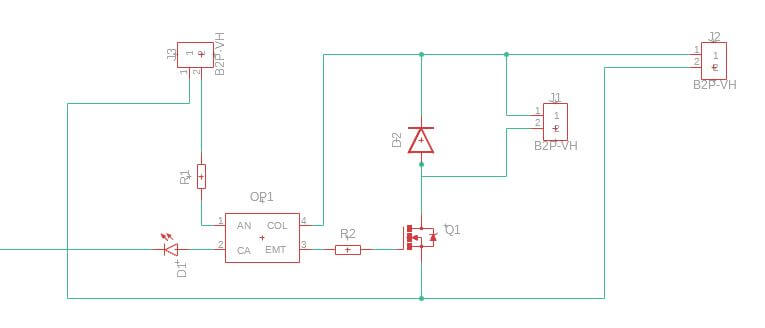
The PCB is designed in Fusion 360 with has the components needed to control the solenoid valves. the main circuit is going to be based on a octocoupler and transistor that is going to control the solenoid valves. This let us use different voltages for the solenoid valves and the raspberry pi.
Before creating the final PCB, I decided to create a test board. This board can control only one solenoid valve. The main idea is to test the SMD components and also the valve. The circuit contains two parts: signal control using 5V to manage this part of the circuit, and power control working with 12V to manage the solenoids.
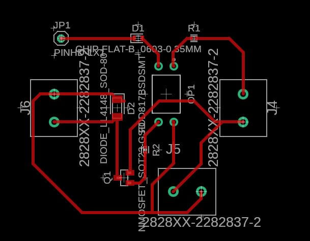
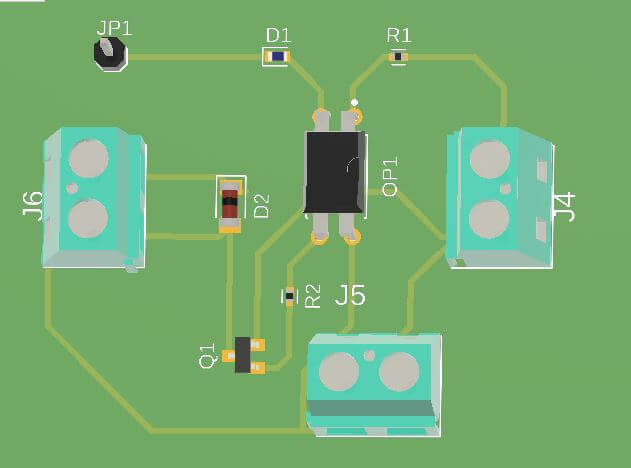
This is the final result or how it looks in the 3D simulation. This allows us to verify if we used the correct components, sizes, path widths, or any details that could affect the performance.
The same circuit is commonly used to control relays, so almost all commercial relay boards will work with this circuit. As you can see in the next picture, this is a typical circuit for a relay module, but in our case, I'm not using relays; I'm controlling the solenoid directly.
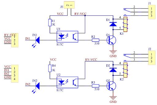
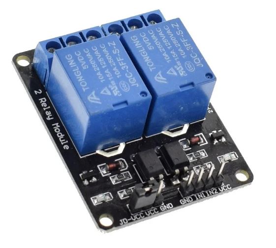
Image Circuite source Circuit Reference
Image Relay source Circuit Reference
The circuit it's really simple some of the components I'm using:
- Resistor
- Diode
- Transistor NPN
- octocoupler
- LED's
Discussing how everything is going to be connected, I created the following diagram showing the distribution of the electronic components. This is just a preview to test the concept, but when I add the rest of the solenoid valves, the circuit will follow the same design with additional Raspberry Pi signals.
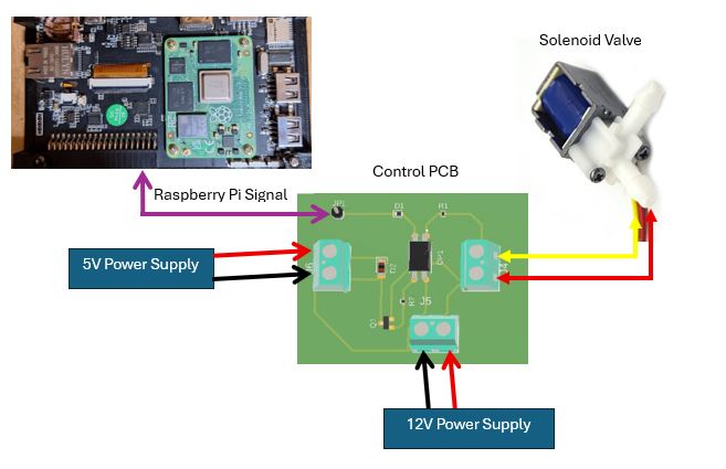
Explaining how everything works: once we select some options on the Raspberry Pi screen, it sends a signal through the GPIO OUTPUT. This signal activates the LED and the optocoupler. As a result, the output of the optocoupler activates the transistor, which then activates the solenoid valve, opening the hose to allow the liquid to flow.
In the coming weeks, we need to test and design the entire hydraulic system and observe how the system performs when incorporating the six solenoid valves required for the complete setup.
Issues
Based on the SMD design for the PCB, finding the components needed for the PCB is a bit challenging because, in my country, the components are not readily available. I need to order the components from other countries, which will take a lot of time. However, to avoid this problem, I can use components from a commercial relay board. These kinds of boards are available in my country and are easily found in the Arduino market in my city.
Project Files links
In the next links, you can download the files for the assignments.
Conclusion
The system integration for the Smart Bartender project is a complex but rewarding process. By carefully selecting and integrating each component, I am creating a functional and efficient automated bartending solution. The combination of the wooden frame, 3D printed parts, Raspberry Pi, and custom PCB will ensure that the system operates smoothly and effectively.
Lessons Learned
This week has taught me the importance of careful planning and design in the system integration process. By creating a detailed design and planning to test it with a scaled-down version, I can ensure that the final product will be successful. Additionally, I have learned about the various fabrication methods and materials used in the project, which will help me make informed decisions in future projects.
Resources