
Week 6
Introduction
This page outlines the steps followed during week 6 of the Fab Academy assignments.
The tasks for this week involved Electronics Design and the following assignments:
- Use the test equipment in your lab to observe the operation of a microcontroller circuit board.
- Use an EDA tool to design a development board that uses parts from the inventory to interact and communicate with an embedded microcontroller
- Extra credit: Try another design workflow.
- Extra credit: Design a case for it.
group assignment:
Individual assignment:
Let's start.....................

Group assignment
Lab Equipment
Before start we need to know the main purpose of the lab equipment that we are going to use. The definition of the equipment is the following:
Function Generator: A function generator is an electronic device that generates different types of electrical waveforms over a wide range of frequencies. The most common waveforms produced by a function generator are sine, square, triangular, and sawtooth waves. Function generators are used in a variety of applications, including testing and troubleshooting electronic circuits, calibrating equipment, and simulating signals for research and development purposes.
Oscilloscope: An oscilloscope is an electronic test instrument that displays electrical signals as a two-dimensional plot of voltage versus time. The vertical axis represents voltage, while the horizontal axis represents time. Oscilloscopes are used to observe and analyze the behavior of electrical signals in real-time, allowing engineers and technicians to troubleshoot and debug electronic circuits.


Image source OSCILLOSCOPE
Power Supply: A power supply is an electronic device that converts electrical power from a source into the correct voltage, current, and frequency to power a load. Power supplies are used in a wide range of applications, including electronics testing, research and development, and industrial automation. They are available in various configurations, such as linear power supplies, switching power supplies, and battery chargers.
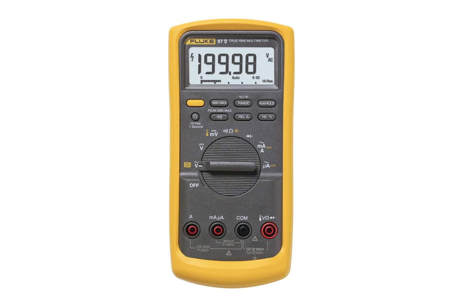
Multimeter: A multimeter is an electronic test instrument that combines several measurement functions in one unit. Multimeters can measure voltage, current, resistance, and other electrical parameters. They are used in a variety of applications, including testing and troubleshooting electronic circuits, checking the continuity of wires and cables, and measuring the resistance of components. Multimeters are available in analog and digital versions, with digital multimeters being the most common type used today.

Image source MULTIMETER
This are some of the equipment that we are going to use in this assignment. The main purpose of this assigment is to understand and learn how to use this equipment to measure different types of signals and components.
Using a ESP32 like a function generator we are going to measure the signals using the oscilloscope. also we are going to use the multimeter to measure the voltage and current of the circuit.
The first step is to connect the ESP32 to the oscilloscope and measure the signals.
we are going to use the following code to generate the signals:
                        #include "Arduino.h"

                        const int analogOutPin = 25; // Pin to output the signal
                        const int freq = 1000; // Frequency in Hz
                        const int resolution = 8; // Resolution in bits

                        void setup() {
                            Serial.begin(115200); // Initialize serial communication
                            ledcSetup(0, freq, resolution); // Setup PWM channel 0
                            ledcAttachPin(analogOutPin, 0); // Attach pin 25 to PWM channel 0
                            xTaskCreate(
                                [](void* parameter) {
                                    while (true) {
                                        int value = analogRead(26); // Read the value from pin 26
                                        Serial.print("Pin 26 value: ");
                                        Serial.println(value); // Print the value
                                        vTaskDelay(pdMS_TO_TICKS(500)); // Delay for 1 second
                                    }
                                },
                                "ReadPinTask", // Name of the task
                                1024,          // Stack size in words
                                NULL,          // Task input parameter
                                1,             // Priority of the task
                                NULL           // Task handle
                            );
                        }

                        void loop() {
                            // Generate a sine wave
                            for (int i = 0; i < 256; i++) {
                                int value = (sin(i * PI / 128) + 1) * 128; // Calculate sine value
                                dacWrite(analogOutPin, value); // Output sine value
                                delay(10); // Delay for smooth waveform
                            }

                            // Generate a square wave
                            for (int i = 0; i < 256; i++) {
                                int value = (i < 128) ? 255 : 0; // Calculate square value
                                ledcWrite(0, value); // Output square value
                                delay(10); // Delay for smooth waveform
                            }
                        }
Code source: Developed by Oscar Gomez
The code is going to generate a sine, square, triangular and sawtooth wave.
The next step is to connect the ESP32 to the oscilloscope and measure the signals.
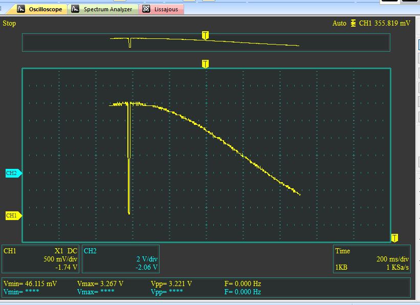
The following images show the signals generated by the ESP32 and measured by the oscilloscope.
The first image shows the sine wave generated by the ESP32.
The second image shows the square wave generated by the ESP32. This type of wave is also known as a digital wave. and is used to PWM signals.
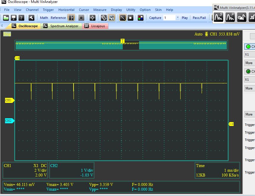
However, we can see that the square wave is not a perfect square wave, this is because in the test we set a higher frequency so with the oscilloscope we can see the behavior of the signal like a duty cycle near 100%.
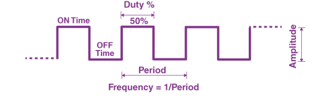
The PWM Signals are used to control the speed of motors, the intensity of the light, and the position of the servo motors.

Image source PWM
This type of practices helps us to understand the behavior of the signals and how to measure them. also, it helps us to understand the behavior of the components and how to measure them.
Individual assignment
The individual assignment for this week is to design a development board that uses parts from the inventory to interact and communicate with an embedded microcontroller. The board should be designed using an EDA tool and should include the following components:
- Microcontroller
- Programming header
- Power supply
- Communication interface
The EDA tool that I used for this assigment is Fusion 360 and Altium Designer, However, this last one has a harder learning curve, so I decided to use Fusion 360 while I finish the tutorials for Altium Designer.

Fusion 360 is a very versatile tool that allows you to design 3D models and PCBs. also, it has a very friendly interface that allows you to design complex models in a few steps.
The first step is to design the schematic of the board. The schematic includes the components and their connections.
We need to include the libraries of the components that we are going to use in the schematic.

In this case we are going to use the following components:
- Microcontroller: XIAO ESP32

Ones, the libraries are included, we can start designing the schematic.
Now we need to include the components in the schematic and connect them.

The main purpose of the board is to control a lot of peripherals that we are going to use in the final project. in this case, we are going to use the following peripherals:
- LEDs
- Buttons
- Relays
- Temperature Sensors
- Distance Sensors
- Power Supplies
- Communication Interfaces
Finishing the schematic, we can start the layout of the board.

Ones we locate all the components in the PCB, we can start routing the connections.


The next step is to design the PCB of the board. The PCB includes the components and their connections in a 2D plane.

This process is very important because it allows us to see the connections of the components and the size of the board.
Finishing the routing process, we can start the manufacturing process of the board.
Fusion 360 provide a 3D view of the board, this is very useful because it allows us to see the connections of the components and the size of the board.

Also, Fusion 360 allows us to get a preview of the whole project, and all the files that we need to manufacture the board.

Issues
The main issue that I had during the design process was the libraries of the components. Some of the components didn't have the libraries in Fusion 360, so I had to add them. This process is very easy, but it takes time. However, the library for the manufacuturer of the board doesn't include a detailed 3D model of the board, just adding a simple IC model. By the other hand, the footprint of the border is really good, and it fits perfectly with the board, so we deside to keep it like that.
Export the Gerber Files
Something really useful about Fusion 360 is that it allows you to export the Gerber Files and generate the G-Code, also it allows you to simulate the milling process.


The gerber files are the files that contain the information of the board, like the connections, the components, and the size of the board. Therefore, we are going to use this files in the next weeks to manufacture the board.


We left the manufacturing process for the Electronics production week, so we can use the same files to manufacture the board.
Project Files links
In the next links, you can download the files for the assignments.
Conclusion
This week we learned how to use the lab equipment to measure the signals and the components. also, we learned how to design a development board using Fusion 360.
Lessons Learned
- How to use the lab equipment
- How to measure the signals and the components
- How to design a development board using Fusion 360
Resources