
Week 8
Introduction
This page outlines the steps followed during week 8 of the Fab Academy assignments.
The tasks for this week involved Electronics Production and the following assignments:
- Characterize the design rules for your in-house PCB production process.
- Submit a PCB design to a board house.
- Make and test a microcontroller development board that you designed.
- Extra credit: make it with another process.
group assignment:
Individual assignment:
Let's start.....................

Group assignment
In-house PCB production
Before start we need to know the equipment that we are going to use to manufacture the board.
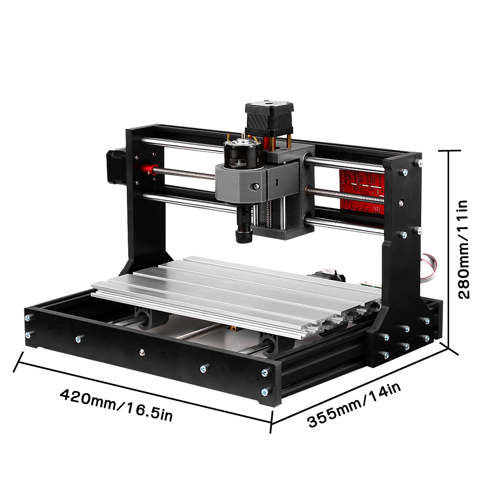
In our case, we are using the CNC 1830 machine for the in-house PCB production process. This machine is capable of milling and drilling the PCB with high precision.


Image source CNC 1830
Image source Offline Controller
PCB Design Rules for CNC 1830
1. PCB Design Constraints
- Minimum Trace Width: 0.3 mm (12 mils)
- Minimum Trace Spacing: 0.3 mm (12 mils)
- Minimum Via Size: 0.6 mm (24 mils)
- Pad Size for Through-Hole Components: 1.5x drill diameter
- Copper Isolation Clearance: 0.4 mm (16 mils)
2. CNC-Specific Considerations
- Milling Bit Size: 0.8 mm - 1.2 mm
- Depth of Cut: 0.1 - 0.2 mm per pass
- Engraving Speed: 100-300 mm/min
- Tool Change Consideration: Use V-shaped or flat-end mills
- Milling Method: Isolation routing
- Copper Layer: Single-layer preferred
3. Material Considerations
- PCB Material: FR4 (1.6 mm) or CEM-1
- Copper Thickness: 1 oz (35 μm)
- Substrate Warping: Minimize with double-sided tape
4. Software & Workflow
- Design Software: KiCad, Eagle, Altium, Fusion 360
- G-code Generation: FlatCAM, PCB-GCode, Mods
- Zeroing & Calibration: Manually zero tool before milling
5. Post-Processing
- Deburring: Light sanding with fine-grit paper
- Tinning: Solder flux and tinning paste
- Component Soldering: Low-temperature soldering
> Testing the PCB design rules is an important step to ensure that the board can be manufactured correctly. This involves checking the trace width, spacing, and other design constraints to ensure that the board can be milled and soldered correctly.
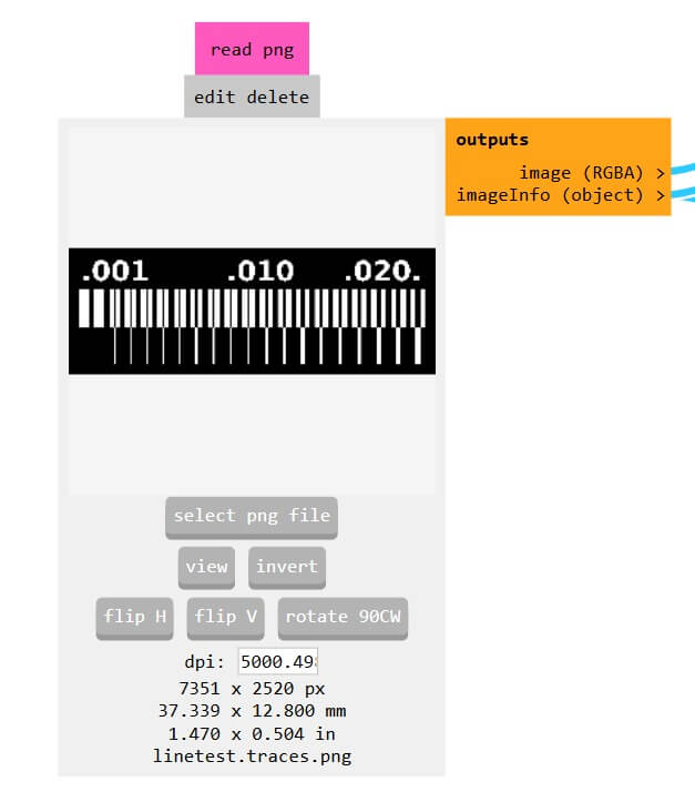
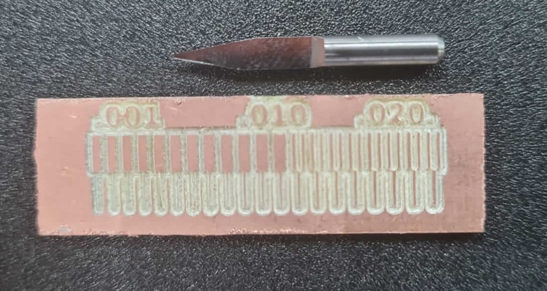
Our first test was to check the traces width and the spacing between them. For this we used a example image we found in the fabacademy website.

To generate the G-code we use the webpage Mosd that allows us to convert the PNG image into a G-code file.
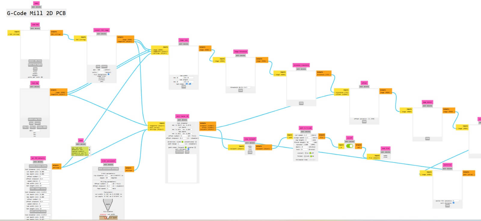
The first step is to upload the image to the webpage.
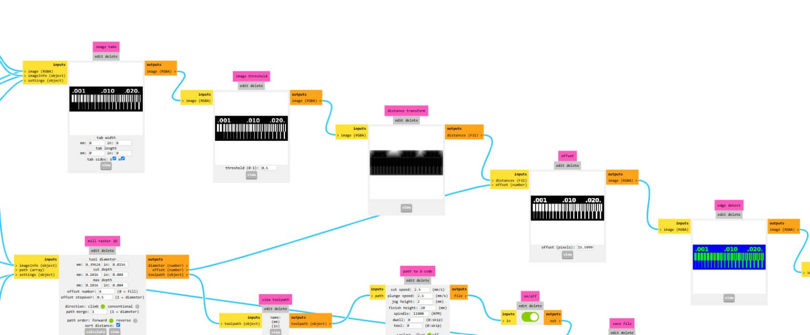
The next step is to set the parameters of the image, like the size of the board, the size of the traces, and the size of the milling bit and other parameters.
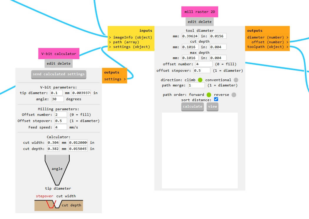
This let us download the G-code file that we are going to use to mill the board.
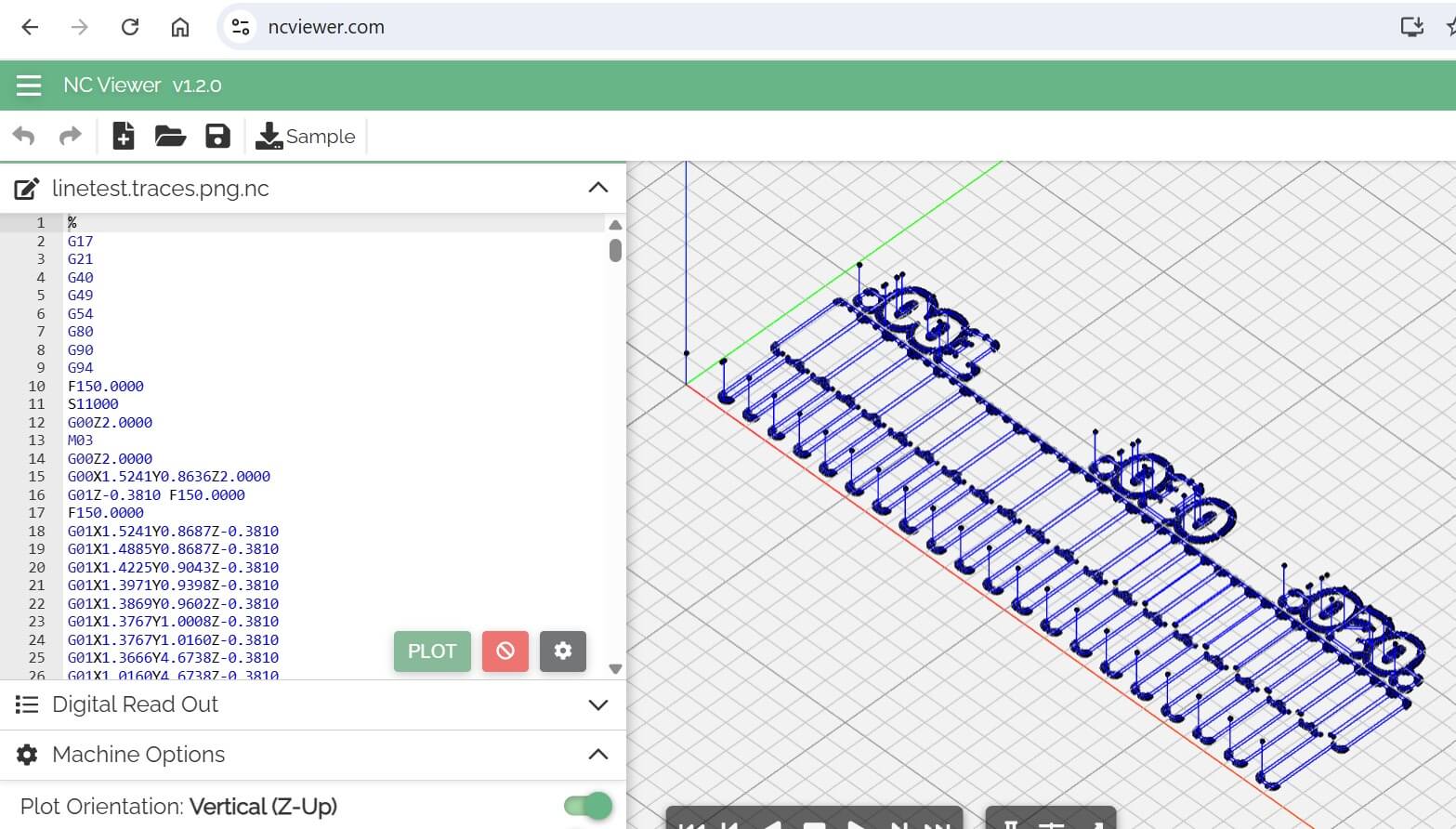
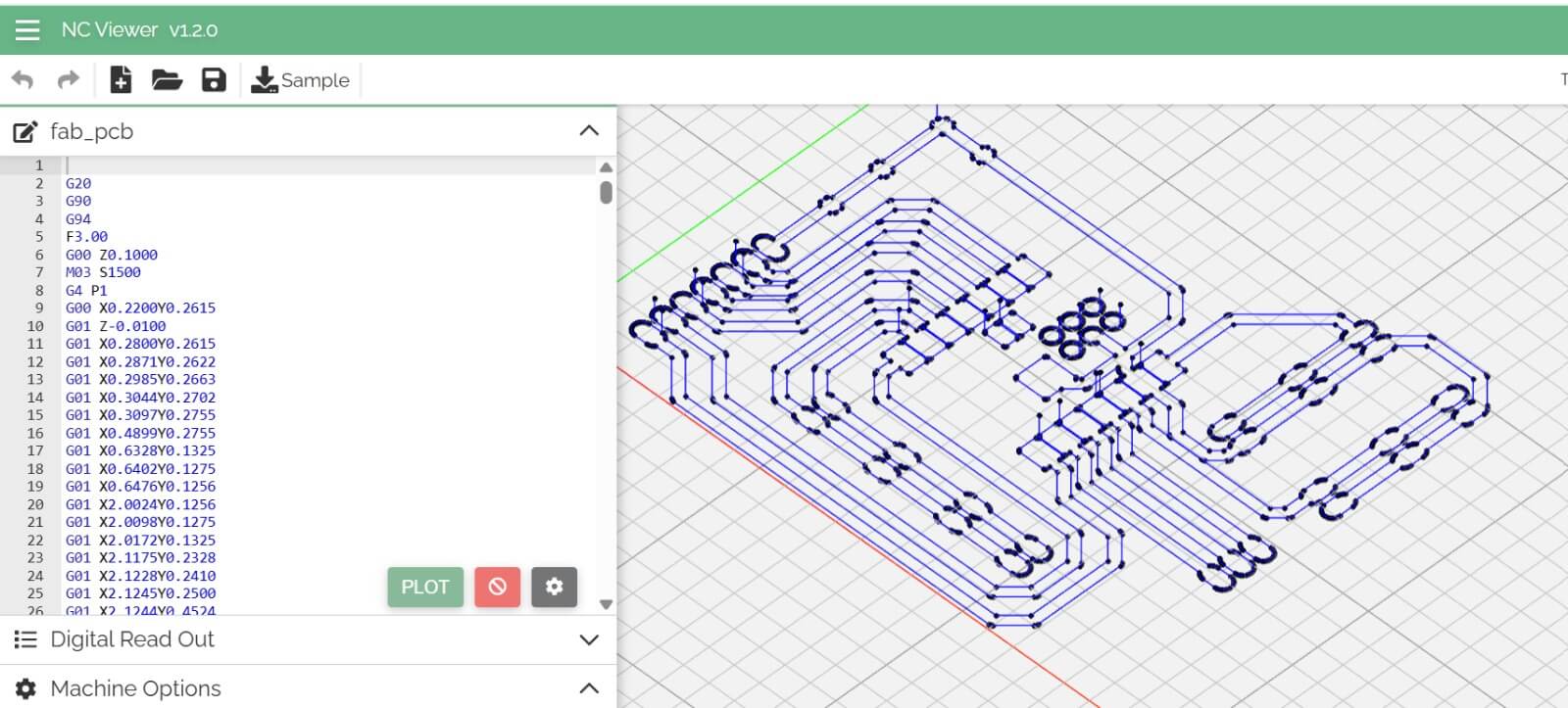
But before we need to check the G-code file to ensure that the traces are correct. For this we use the webpage G-Code Simulator that allows us to see the traces of the G-code file.
The webpage we use is NC Viewer G-Code Simulator and the file looks like this.
The next step is to mill the board using the CNC 1830 machine.
Submit Gerber files to a board house
The next step is to submit the Gerber files to a board house. This process is very important because it allows us to manufacture the board with high precision and quality.
The board house that we are going to use is JLCPCB.
The first step is to create an account in the webpage and upload the Gerber files.

Then we are able to upload the Gerber files and see the preview of the board.
The next step is to select the parameters of the board, like the size of the board, the number of layers, the thickness of the board, and other parameters.


The last step is to pay for the board and wait for the delivery.
Individual assignment
Make a PCB board
For this assignment, we are going to design a development board using Fusion 360. the board we are going to mill is the design of the week 6 assignment.
After we have the design of the board, and we have all the components placed in the board, and the routing process done, we can start the manufacturing process.

Fusion 360 provide a 3D view of the board, this is very useful because it allows us to see the connections of the components and the size of the board.

Also, Fusion 360 allows us to get a preview of the whole project, and all the files that we need to manufacture the board.

Export the Gerber Files
Something really useful about Fusion 360 is that it allows you to export the Gerber Files and generate the G-Code, also it allows you to simulate the milling process.


The gerber files are the files that contain the information of the board, like the connections, the components, and the size of the board. Therefore, we are going to use this files in the next weeks to manufacture the board.


we need to know that this gerber files are the same we uses to submit to the board house, and the same we use to manufacture the board in the CNC 1830 machine.
Manufacture the board
The next step is to manufacture the board using the CNC 1830 machine.
For generate the G-code we use the software FlatCAM that allows us to convert the Gerber files into G-code files.

The fist step is to load the Gerber files into the software.
The next step is to set the parameters of the milling process, like the size of the milling bit, the depth of the cut, and other parameters.
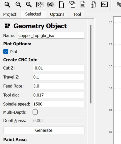
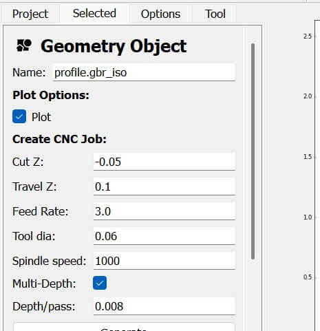
We set the parameters of the traces and profile of the board.
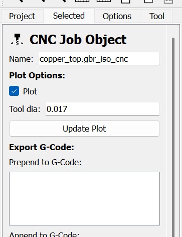
The next step is to generate the G-code file that we are going to use to mill the board.
The software allows us to see the path of the milling bit and the traces of the board.
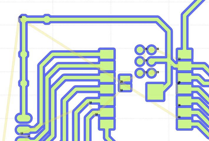
we also have a genaral view of the board, this allows us to see the traces and check if the board is correct.
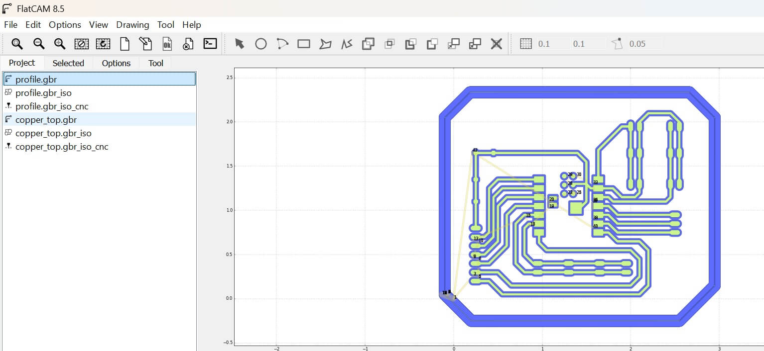
If all the parameters are correct, we can start the milling process. But fist we generate the G-code file.
The next step is to load the G-code file into the CNC 1830 machine and start the milling process. For this step we use the offline controller of the machine.
But first using the machine we check the G-files on the webpage NC Viewer G-Code Simulator, this to ensure that the traces are correct.
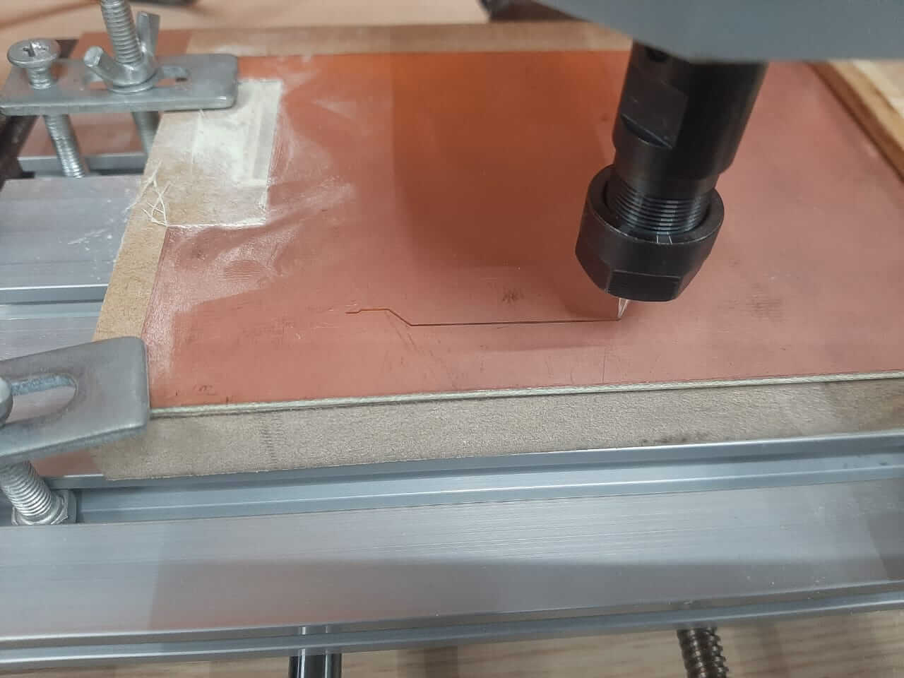
Before starting the milling process we need to set the zero point of the milling bit, this is very important because it allows us to mill the board in the correct position.
The fist step is to set the zero point of the milling bit in the X and Y axis. Once we have the zero point of the milling bit in the X and Y axis, we need to set the zero point in the Z axis. Then we can start the milling process.
Issues
The fist try was not successful, the milling bit was not in the correct position, the zero point in the Z axis was not correct. Therefore, we need to set the zero point of the milling bit again.
The next try was successful, the milling bit was in the correct position and the milling process was correct.
However when we check the result we found that the milling bit was not in good shape and the milling process was not correct, because the milling bit mill more Material than expected, and the traces were not correct.
The next step is to mill the board again, but this time we are going to use a new milling bit.
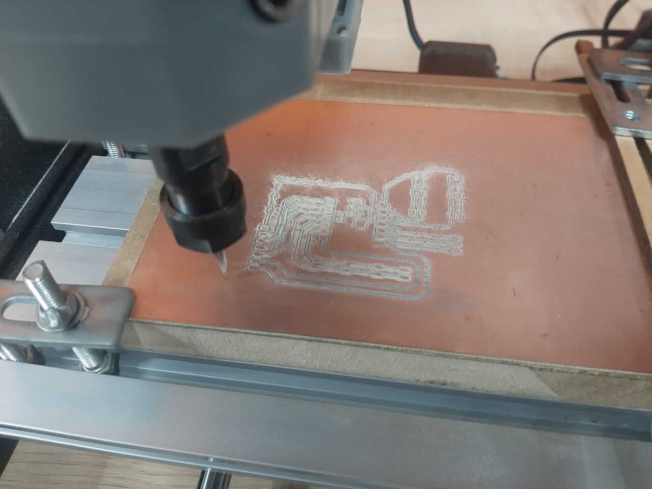
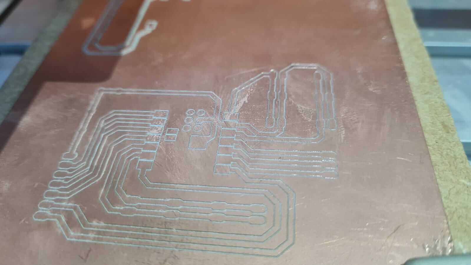
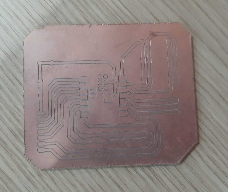
The new milling bit was in good shape and the milling process was correct. This gave us a good result in the board.
Then we mill the profile of the board, this to separate the board from the material.
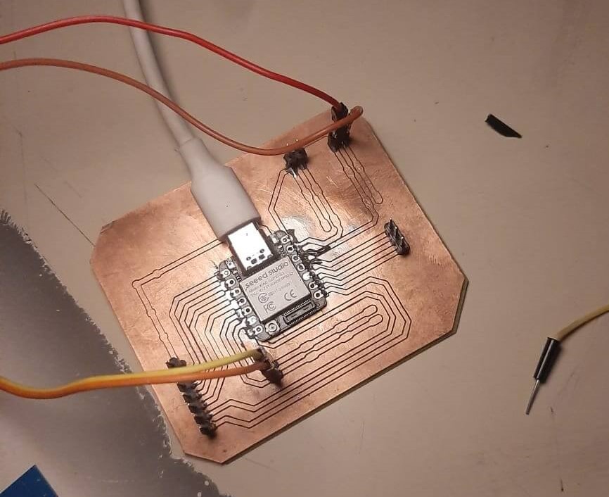
The next step is to solder the components and test the board.
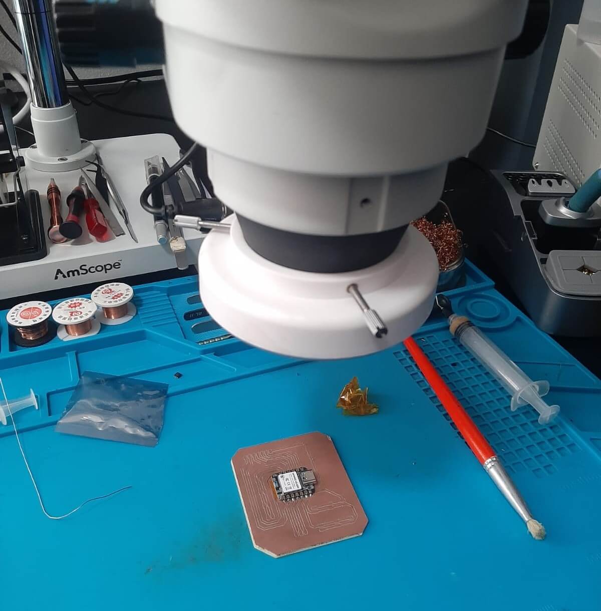
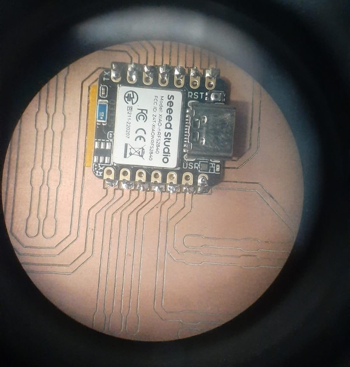
The board was correct and all the components were connected correctly.
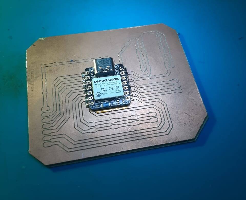
HERO SHOT
Project Files links
In the next links, you can download the files for the assignments.
- PCB Fusion 360 Project
- Project Gerber Files
- Traces PCB G-code File
- Profile Traces PCB G-code File
- Fab PCB project G-code File
- Profile Fab PCB project G-code File
Conclusion
The in-house PCB production process is a very useful tool for rapid prototyping and testing of PCB designs. It allows us to quickly iterate on designs and test different configurations without having to wait for a board house to manufacture the board.
Lessons Learned
- Check the design rules before manufacturing the board
- Use the correct milling bit for the traces and profile
- Set the zero point of the milling bit correctly
- Check the G-code file before milling the board
- Test the board after manufacturing to ensure that it works correctly
Resources