
Week 9
Introduction
This page outlines the steps followed during week 9 of the Fab Academy assignments.
The tasks for this week involved Input Devices and the following assignments:
- Probe an input device's analog levels and digital signals.
- Measure something: add a sensor to a microcontroller board that you have designed and read it.
group assignment:
Individual assignment:
Let's start.....................

Group assignment
Analog levels and digital signals
To measure the analog levels and digital signals we are going to use the oscilloscope. The oscilloscope is a very useful tool that allows us to measure the signals and the components of the circuits.
Before start we need to known the following concepts, Analog signals are continuous signals that vary in time. Digital signals are discrete signals that have two values, 0 and 1.
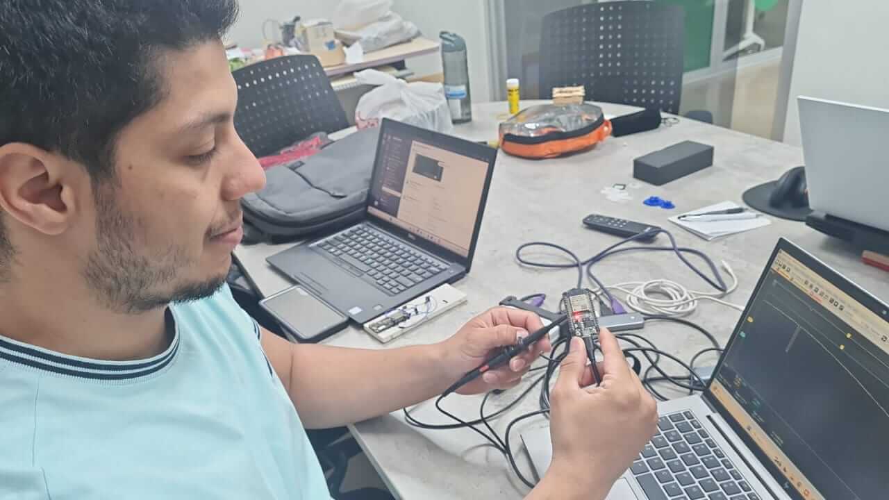
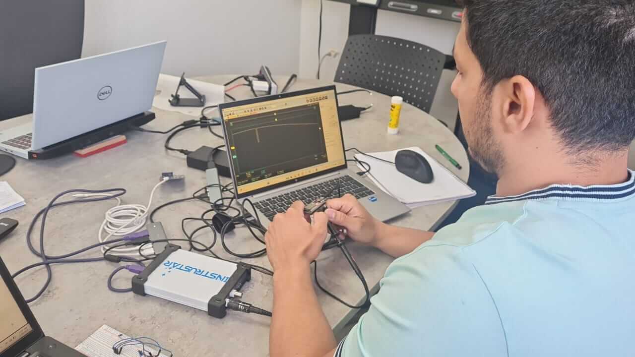
Using a ESP32 like a function generator we are going to measure the signals using the oscilloscope and also read the analog values generated for the analog output of the ESP32.
The first step is to connect the ESP32 to the oscilloscope and measure the signals.
we are going to use the following code to generate the signals:
                        #include "Arduino.h"

                        const int analogOutPin = 25; // Pin to output the signal
                        const int freq = 1000; // Frequency in Hz
                        const int resolution = 8; // Resolution in bits

                        void setup() {
                            Serial.begin(115200); // Initialize serial communication
                            ledcSetup(0, freq, resolution); // Setup PWM channel 0
                            ledcAttachPin(analogOutPin, 0); // Attach pin 25 to PWM channel 0
                            xTaskCreate(
                                [](void* parameter) {
                                    while (true) {
                                        int value = analogRead(26); // Read the value from pin 26
                                        Serial.print("Pin 26 value: ");
                                        Serial.println(value); // Print the value
                                        vTaskDelay(pdMS_TO_TICKS(500)); // Delay for 1 second
                                    }
                                },
                                "ReadPinTask", // Name of the task
                                1024,          // Stack size in words
                                NULL,          // Task input parameter
                                1,             // Priority of the task
                                NULL           // Task handle
                            );
                        }

                        void loop() {
                            // Generate a sine wave
                            for (int i = 0; i < 256; i++) {
                                int value = (sin(i * PI / 128) + 1) * 128; // Calculate sine value
                                dacWrite(analogOutPin, value); // Output sine value
                                delay(10); // Delay for smooth waveform
                            }

                            // Generate a square wave
                            for (int i = 0; i < 256; i++) {
                                int value = (i < 128) ? 255 : 0; // Calculate square value
                                ledcWrite(0, value); // Output square value
                                delay(10); // Delay for smooth waveform
                            }

                            // Generate a triangular wave
                            for (int i = 0; i < 256; i++) {
                                int value = (i < 128) ? i * 2 : (255 - i) * 2; // Calculate triangular value
                                dacWrite(analogOutPin, value); // Output triangular value
                                delay(10); // Delay for smooth waveform
                            }

                            // Generate a sawtooth wave
                            for (int i = 0; i < 256; i++) {
                                int value = i; // Calculate sawtooth value
                                dacWrite(analogOutPin, value); // Output sawtooth value
                                delay(10); // Delay for smooth waveform
                            }
                        }
Code source: Developed by Oscar Gomez
The code is going to generate a sine, square, triangular and sawtooth wave. However, we are going to use the sine wave to measure the signals this represent the analog signals and the square to represent the digital signals.
The next step is to connect the ESP32 to the oscilloscope and measure the signals.
The following images show the signals generated by the ESP32 and measured by the oscilloscope.
The first image shows the sine wave generated by the ESP32.


In the next images you can see me using the oscilloscope to measure the signals.
We also read the analog values generated by the ESP32 using the analog output of the ESP32. In this case we used the pin 26 to read the values.
The esp32 has a 12-bit DAC that allows us to generate analog signals. The DAC is a digital-to-analog converter that converts the digital signals to analog signals. The DAC has a resolution of 12 bits, so it can generate 4096 different values. The resolution of the DAC is the number of bits that the DAC can generate.

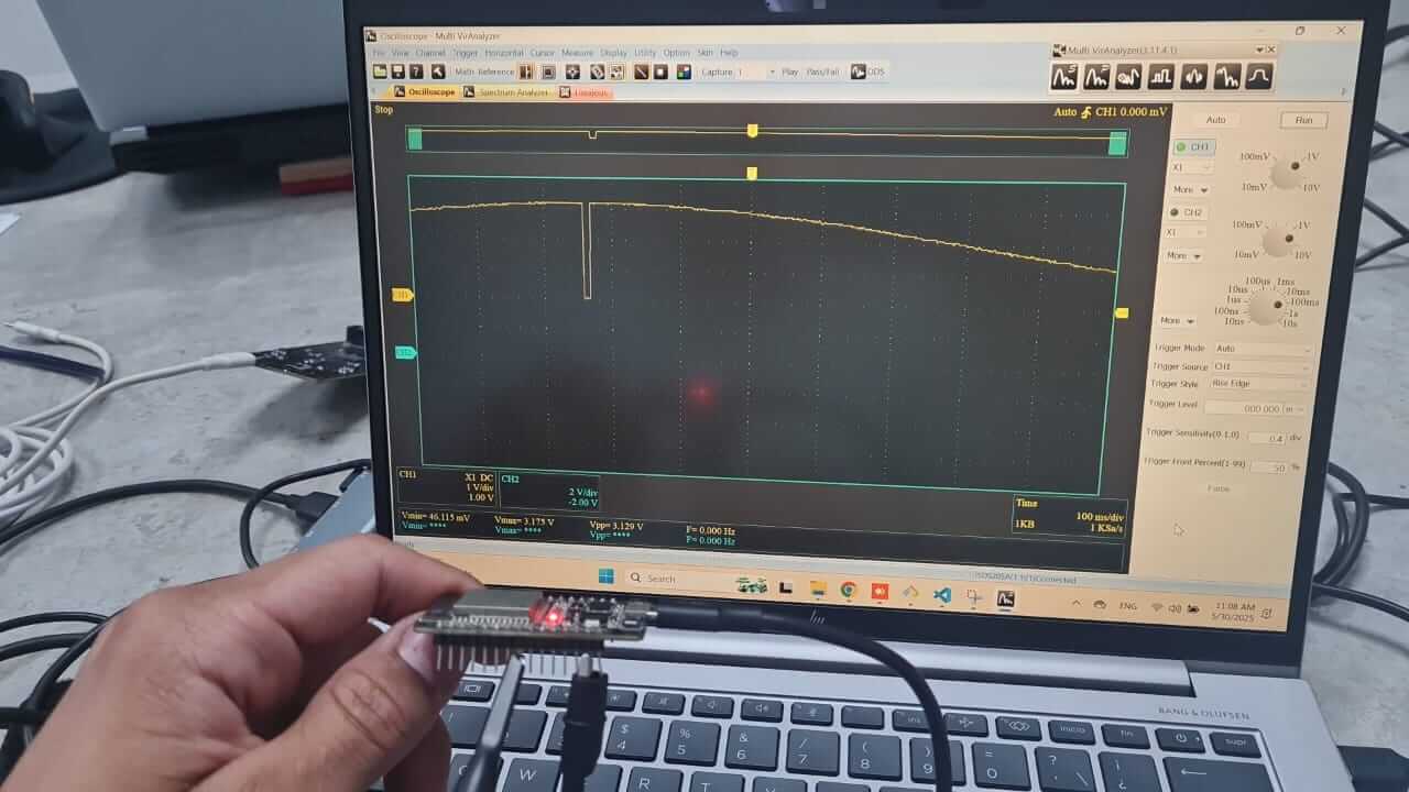
The second image shows the square wave generated by the ESP32. This type of wave is also known as a digital wave. and is used to PWM signals.
In this image we can see the square wave with almost 99% of duty cycle. So, we are able to the the fallin and rising edge of the signal.

The PWM Signals are used to control the speed of motors, the intensity of the light, and the position of the servo motors.

Image source PWM
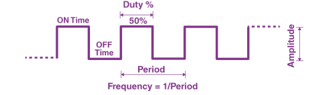
Different of analog signals, the digital signals have two values, 0 and 1. In this case we use the same pin 26 to read the values. So, we can see the values of the digital signals and this change from 0 to 4095. This last value is the maximum value that the ESP32 can generate using the DAC, this value is the equivalent to 3.3V or 1 in the digital signals.

This type of practices helps us to understand the behavior of the signals and how to measure them. also, it helps us to understand the behavior of the components and how to measure them.
Individual assignment
Measure something
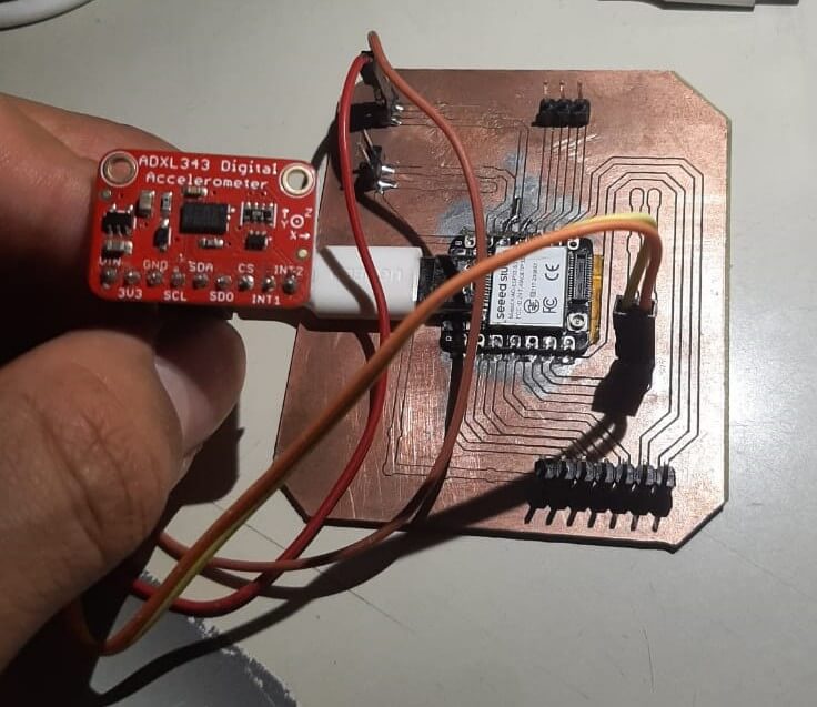
For this part I used a esp32 with a ADXL343 accelerometer to measure the acceleration of the board.
The ADXL343 is a 3-axis accelerometer that allows us to measure the acceleration of the board. The accelerometer has a resolution of 13 bits, so it can measure the acceleration with a resolution of 0.001g.
The ADXL343 has a range of ±16g, so it can measure the acceleration from -16g to 16g.
ESP32 with ADXL343 using I2C
The ADXL343 accelerometer communicates with microcontrollers like the ESP32 using the I2C protocol. I2C (Inter-Integrated Circuit) is a synchronous, multi-master, multi-slave, packet-switched, single-ended, serial communication bus. It is widely used for connecting low-speed peripherals to processors and microcontrollers.
Understanding the I2C Protocol
- Master-Slave Architecture: The ESP32 acts as the master, and the ADXL343 acts as the slave device.
- Two-Wire Communication: I2C uses two lines: SDA (Serial Data Line) for data transfer and SCL (Serial Clock Line) for clock signals.
- Addressing: Each slave device has a unique 7-bit or 10-bit address. The ADXL343 typically uses the address
0x53or0x1D, depending on the configuration of its address pin. - Data Transfer: Data is transferred in packets, starting with a start condition and ending with a stop condition. Each byte is followed by an acknowledgment (ACK) or no acknowledgment (NACK).
Connecting the ESP32 to the ADXL343
To connect the ESP32 to the ADXL343, follow these steps:
- Connect the SDA pin of the ADXL343 to the ESP32's SDA pin (default GPIO21).
- Connect the SCL pin of the ADXL343 to the ESP32's SCL pin (default GPIO22).
- Connect the VCC pin of the ADXL343 to a 3.3V power source.
- Connect the GND pin of the ADXL343 to the ground of the ESP32.
- Optionally, add pull-up resistors (4.7kΩ) to the SDA and SCL lines if not already present on the ADXL343 breakout board.
Code Example for Reading Data from ADXL343
Below is an example code to initialize the I2C communication and read acceleration data from the ADXL343:
                           #include "Wire.h"
                           #include "Adafruit_Sensor.h"
                           #include "Adafruit_ADXL343.h"

                           #define SDA_PIN 5 // SDA pin for ESP32
                           #define SCL_PIN 6 // SCL pin for ESP32

                           Adafruit_ADXL343 accel1 = Adafruit_ADXL343(12345);

                           void setup(void)
                           {
                             Serial.begin(115200);
                             while (!Serial);

                             Wire.begin(SDA_PIN, SCL_PIN); // Initialize I2C with custom SDA and SCL pins

                             // I2C Scanner
                             Serial.println("Scanning for I2C devices...");
                             byte count = 0;
                             for (byte address = 1; address < 127; address++) {
                               Wire.beginTransmission(address);
                               if (Wire.endTransmission() == 0) {
                                 Serial.print("Found I2C device at address 0x");
                                 if (address < 16) Serial.print("0");
                                 Serial.println(address, HEX);
                                 count++;
                               }
                             }
                             if (count == 0) {
                               Serial.println("No I2C devices found.");
                             } else {
                               Serial.print("Found ");
                               Serial.print(count);
                               Serial.println(" I2C devices.");
                             }
                             Serial.println("");

                             /* Initialise the first sensors, this uses the default address */
                             if(!accel1.begin(0x53))
                             {
                               /* There was a problem detecting the ADXL343 ... check your connections */
                               Serial.println("Ooops, no ADXL343 nr1 detected ... Check your wiring!");
                               while(1);
                             }

                             /* Set the range and data rate to whatever is appropriate for your project */
                             /* See the sensortest example for more details */
                             accel1.setRange(ADXL343_RANGE_2_G);

                             accel1.setDataRate(ADXL343_DATARATE_1600_HZ);

                             /* Display some basic information on these sensors */
                             accel1.printSensorDetails();
                             Serial.println("");
                           }

                           void loop(void)
                           {
                             /* Get new sensor events */
                             sensors_event_t event1;
                             accel1.getEvent(&event1);

                             /* Display the results (acceleration is measured in m/s^2) */
                             Serial.print("X: ");Serial.print(event1.acceleration.x); Serial.print(", ");
                             Serial.print("Y: ");Serial.print(event1.acceleration.y); Serial.print(", ");
                             Serial.print("Z: ");Serial.print(event1.acceleration.z); Serial.println(".");
                             delay(2000);
                           }
Code source: Github Repository
Explanation of the Code
- The code initializes the I2C communication using the
Wire.begin()function. - The code scans for I2C devices connected to the ESP32 using the I2C scanner.
- The code initializes the ADXL343 accelerometer using the
accel1.begin()function. - The code sets the range and data rate of the accelerometer using the
accel1.setRange()andaccel1.setDataRate()functions. - The code reads the acceleration data from the accelerometer using the
accel1.getEvent()function. - The code prints the acceleration data to the serial monitor.
In the next image we can see the info and acceleration of the board in the x, y and z axis.


However, in the next image we can se the PCB that we are going to use to connect the accelerometer. The PCB is a very simple PCB that we development in the previous weeks. the link to the PCB is:
HERO SHOT
Issues
For this week, we didn't have any issues with the assignments, because I had experience working with the ESP32 and the ADXL343 accelerometer. However, I have some recommendations for the future:
- Check the connections of the components before start.
- Use the I2C scanner to check if the components are connected.
- Use the oscilloscope to measure the signals and check if they are correct.
- Use the serial monitor to check if the values are correct.
- Use the datasheet of the components to check the values and the connections.
- Use the library documentation to check the functions and the parameters.
- Use the examples of the library to check if the code is correct.
- Use the comments in the code to check if the code is correct.
Conclusion
In conclusion, this week provided valuable insights into the use of input devices and their integration with microcontrollers. By exploring both analog and digital signals, I gained a deeper understanding of how to measure and interpret these signals using tools like oscilloscopes. Additionally, working with the ESP32 and ADXL343 accelerometer allowed me to enhance my knowledge of I2C communication and sensor data acquisition. These hands-on experiences have significantly improved my ability to design and implement systems that interact with the physical world, which is a crucial skill in electronics and embedded systems development.
Lessons Learned
- Understanding the difference between analog and digital signals and their practical applications.
- Learning how to use an oscilloscope to measure and analyze signal waveforms.
- Gaining experience in generating various waveforms (sine, square, triangular, sawtooth) using the ESP32.
- Exploring the I2C protocol and its implementation for communication between the ESP32 and ADXL343 accelerometer.
- Acquiring knowledge about the ADXL343 accelerometer and its capabilities for measuring acceleration.
- Improving skills in debugging and troubleshooting hardware connections and code.
- Enhancing understanding of PWM signals and their use in controlling devices like motors and LEDs.
- Recognizing the importance of hands-on experimentation for learning electronics and embedded systems.
Resources