Wheaton Fab Lab Group Documentation: Week 12
Mechanical Design, Machine Design
Created by Casimir Maksymowicz, Gillian Cote, Hanna Ondrasek, Jadelyn Wilson Joutras, Sierra Nieves, Sierra Seetin, and Tammi Redd
Overview
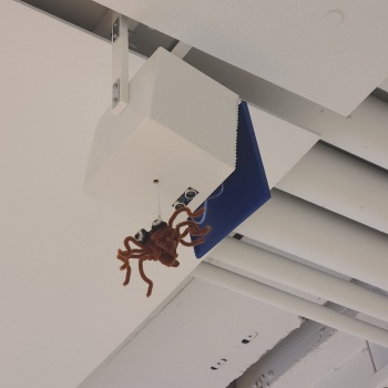
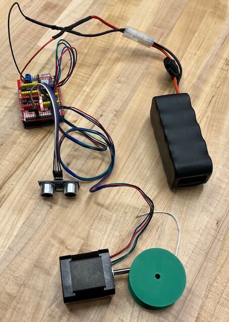
We created a machine that drops a spider from the ceiling whenever motion is detected. The electronic hardware for this project included the Arduino Uno, an ultrasonic sensor, and the NEMA 17 stepping motor.
Brainstorming
We started by brainstorming ideas for a machine. Some of our top picks were a countdown machine for people racing and a high five machine. We went with the spider spooking machine because we had the general idea of the mechanism, which is a pulley on a motor with a motion sensor.
Plan/Measurements
For ease of planning and design, we had a shared document with measurements for all of the components we were using
        Stepper Motor
          - Width & Length of box: 42.3 mm
          - Height of box: 47.6 mm
          - Diameter of shaft: 5 mm
          - Diameter of shaft with flat side: 4.5 mm
          - Length of Shaft: 25.4 mm (1 inch)
          - Weight: 362 g
        Motor lift (rectangular platform)
          -Length 51 mm
          -Width 38 mm
        Microcontroller - Arduino Uno & Motor Controller
          - Width: 53.9 mm
          - Length: 70.75 mm
          - Height: 33.6 mm
          -  Weight: 77 g
        String
        - Fishing line
        -  String in the lab
        -  67 inches
        Spider (Fil)
        - Weight: 14 g
        Modern Robotics 12V 3000mAh NIMH battery
        -  Width: 45.8mm
        -  Length: 115 mm
        -  Height: 47.2 mm
        -  Weight: 596 g
        Ultrasonic Sensor
        -   Sensor length: 42mm
        -  Sensor width: 15.9mm
        -  Sensor height: 12.25mm
        -  Board length: 45.4 mm
        -  Board width: 20.4 mm
Group Documentation
Fusion360 spool file (STL)
PrusaSlicer spool file (BGCode)
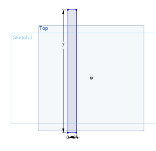
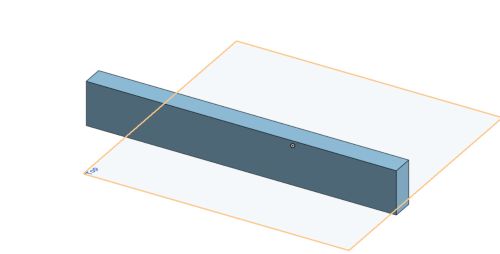
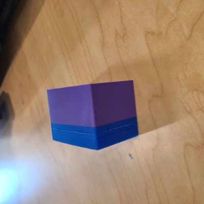
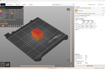
Motor Platform
Support Platform for Motor
We designed a platform for the motor to sit on using Fusion 360. The motor couldn't sit on the floor of the box as it would interupt the motor revolutions and cause the string to tangle. We 3D printed a block about the same size of the motor to lift the motor off the floor of the box by about an inch. This made for enough clearance for the spool to rotate freely and keep the string from tangling.
Hardware
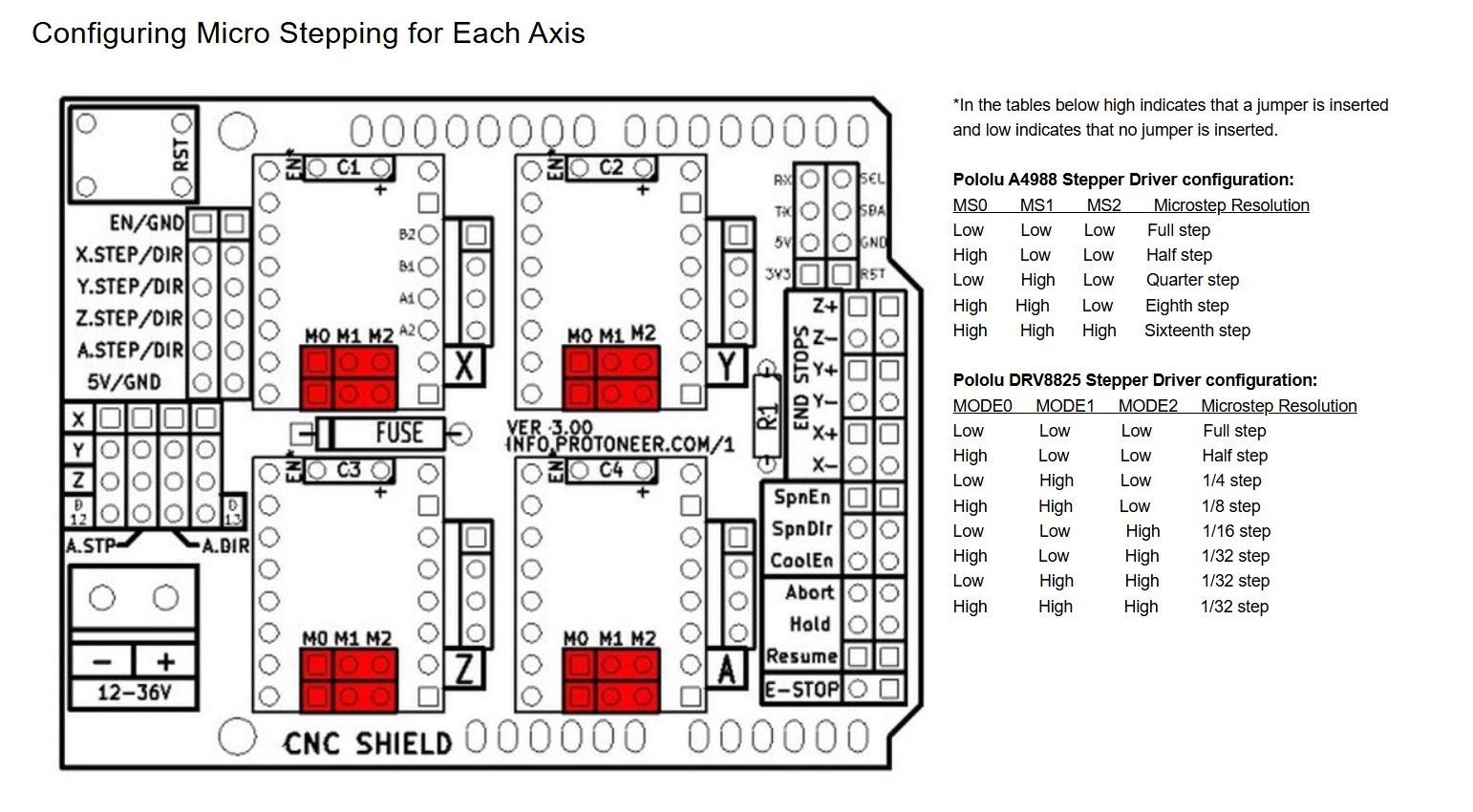
CNC Shield, Stepper Motor, & Ultrasonic Sensor
We used quarter steps for the stepper motor to ensure a less jerky movement. View the stepper driver configuration below (src here).
We used pins D12 & D13 for the ultrasonic sensor. It's important to ensure that the pins being used aren't also being used for the stepper motor (using the pins on the right side is a safe choice). We also plugged in the sensor to the 5V and GND pins on the right side of the shield. We needed a seperate battery for the arduino to work, so we used a personal charger.
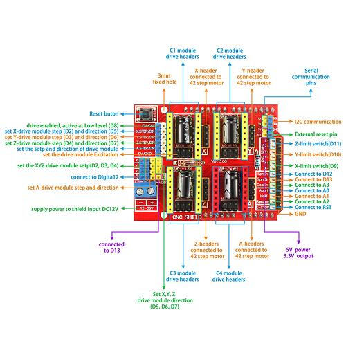
The finished wiring (battery not shown, battery replaces plug-in).

Now, it's important to calculate number of steps required for the spider to travel 10 feet. We used the radius of the spindle and the number of quarter steps in a revolution to calculate this.
          1 revolution total length of string if spindle has a radius of 0.79 in =


          =4.96 inch circumference (spider falls 4.96 inches/revolution)

          Full step = 200 steps per revolution

          Quarter step = 800 steps per revolution

          Find inches per step:

          4.96/800 = 0.0062 inches/step

          Solve for x (number of steps):

          0.0062 * x = 84 inches(7’)

          84 / 0.0062 = 13548 steps for the spider to fall 7 feet in quarter step mode


        we'll make it 12000 just to be safe lol, using excess string would be bad
Code for just the ultrasonic sensor
          #include "Ultrasonic.h"

/*
   Pass as a parameter the trigger and echo pin, respectively,
   or only the signal pin (for sensors 3 pins), like:
   Ultrasonic ultrasonic(13);
*/
Ultrasonic ultrasonic(12, 13);
int distance;
int headHeight = 24; // in inches


void setup() {
  Serial.begin(9600);
}

int increment = 0;
void loop() {
  // Pass INC as a parameter to get the distance in inches


  distance = ultrasonic.read(INC);

  Serial.print("Distance in Inches: ");
  Serial.println(distance);

  // make an incrementor, increment goes up for each distance less than 24, if the increment reaches 5 (on i=5),
  // deploy

  if (distance < headHeight) {

  increment++;
  Serial.println(increment);
  if (increment == 5) {
    Serial.println("deploy spider");
    increment = 0;
  }
  } else{
    Serial.println("dont deploy spider");
  }
delay(5000);
}
Motor+sensor code integrated together.
There were a few additions to this code that will be discussed further down this page.
            // Basic CNC shield stepper motor example.
            #include "Ultrasonic.h"

            /*
               Pass as a parameter the trigger and echo pin, respectively,
               or only the signal pin (for sensors 3 pins), like:
               Ultrasonic ultrasonic(13);
            */
            Ultrasonic ultrasonic(12, 13);
            int distance;
            int headHeight = 24; // in inches

            // motor stuff
            int enablePin = 8;
            int stepPin = 2;
            int dirPin = 5;
            int dir = LOW;
            int speed =1000; // Steps per second
            int dist = 12000; // Total number of steps to move (approx 6 feet)

            void setup() {
              Serial.begin(9600);
              // put your setup code here, to run once:
              pinMode(enablePin,OUTPUT);
              pinMode(stepPin,OUTPUT);
              pinMode(dirPin,OUTPUT);

              // do the code below to ensure the motor isn't trying to spin before
              // we meet the conditions for deploying the spider
              digitalWrite(enablePin,HIGH);
              digitalWrite(stepPin, LOW);
              digitalWrite(dirPin, dir);
            }

            int increment = 0;
            void loop() {
              distance = ultrasonic.read(INC);

              Serial.print("Distance in Inches: ");
              Serial.println(distance);

              // make an incrementor, increment goes up for each distance less than 24, if the increment reaches 5 (on i=5),
              // deploy

              if (distance < headHeight) {

              increment++;
              Serial.println(increment);

              // on the 5th read less than 24 inches, start the motor running code
              if (increment == 5) {
                Serial.println("deploy spider");
                digitalWrite(enablePin, LOW);  // start motor
                digitalWrite(dirPin,dir);
                for (int i = 0; i < dist; i++) {
                  digitalWrite(stepPin, LOW);
                  delayMicroseconds(300);
                  digitalWrite(stepPin, HIGH);
                  delayMicroseconds(300);
                }

                delay(10000);
                dir = !dir;

                for (int i = 0; i < dist; i++) {
                  digitalWrite(stepPin, LOW);
                  delayMicroseconds(500); // a bit slower when going up
                  digitalWrite(stepPin, HIGH);
                  delayMicroseconds(500);
                }
                digitalWrite(enablePin, HIGH); // disable motor after move
                increment = 0;
                delay(10000); // delay after spider has been deployed
              }
              } else{
                Serial.println("dont deploy spider");
              }
              delay(5000);
            }
Spool design
The original spool's edges were too low, so the string would occasionally jump off. This is our discussion of the new spool design we made.
We made the hole measurement by measuring the shaft of the stepper motor in mm. We accounted for (measured) the flat edge of the stepper motor, too, so this design fits very snugly on the stepper.
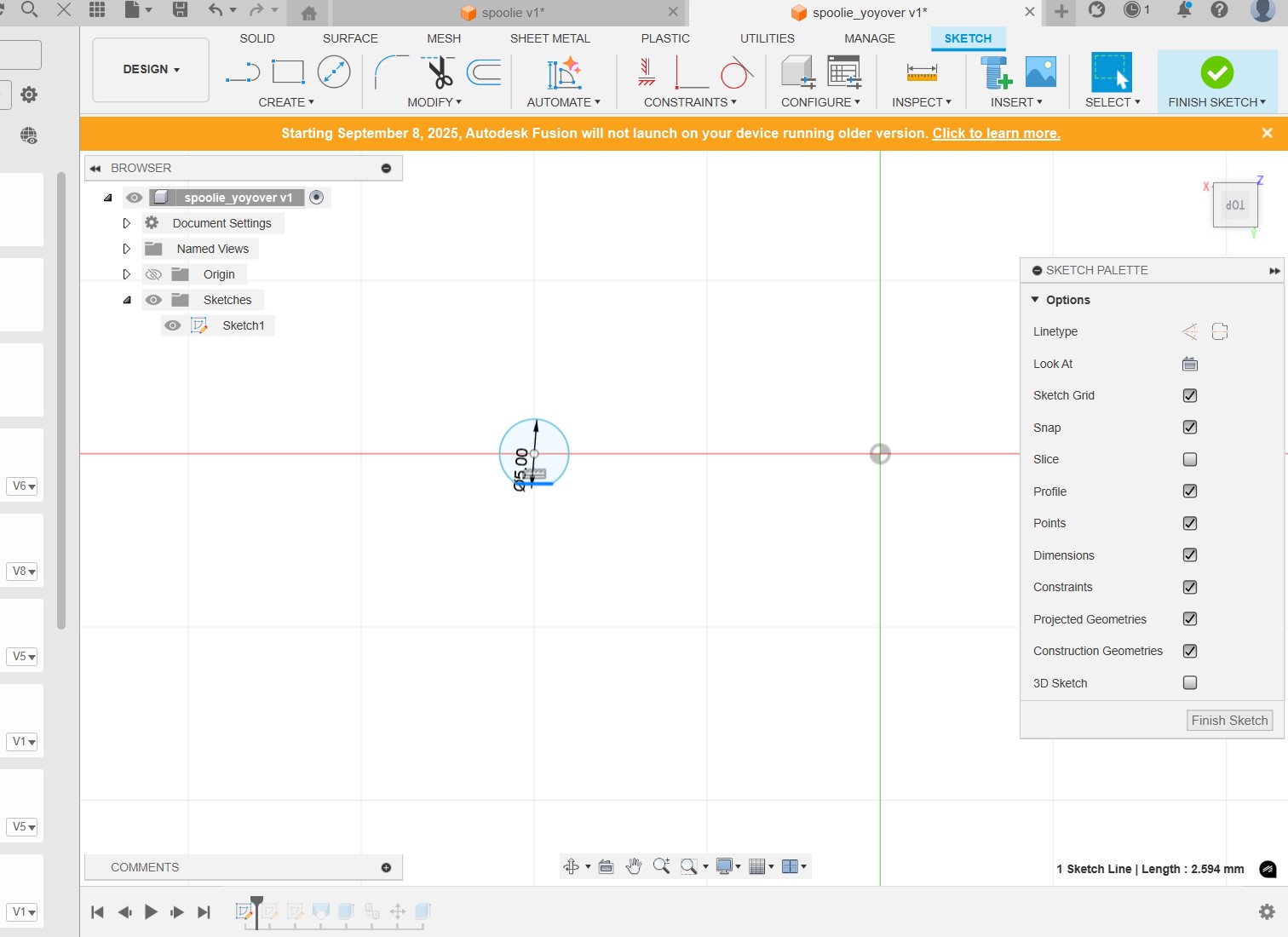
Next, we made a larger circle near the hole, and a smaller circle moved 12 mm above. This will make our desired "yoyo" shape that would keep the string in place.
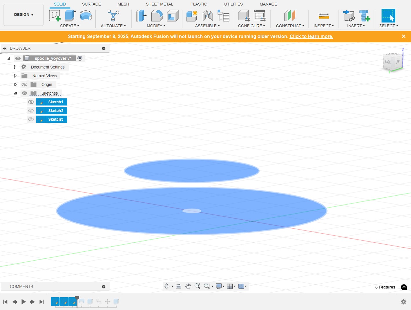
Next, we used the loft tool to connect the 2 circles. Extrude the tiny hole sketch in the negative direction to make a hole in this body.

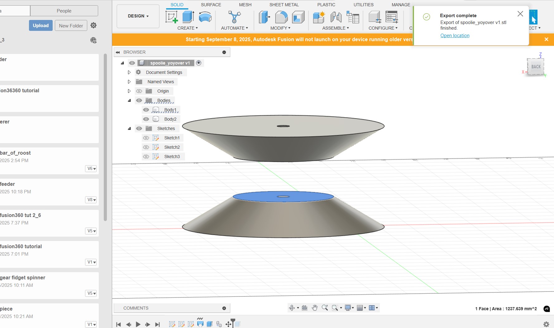
We copied that body and rotated it 180 degrees. Extrude the smaller circle at the bottom, which is where the string will rotate around.
The final design.
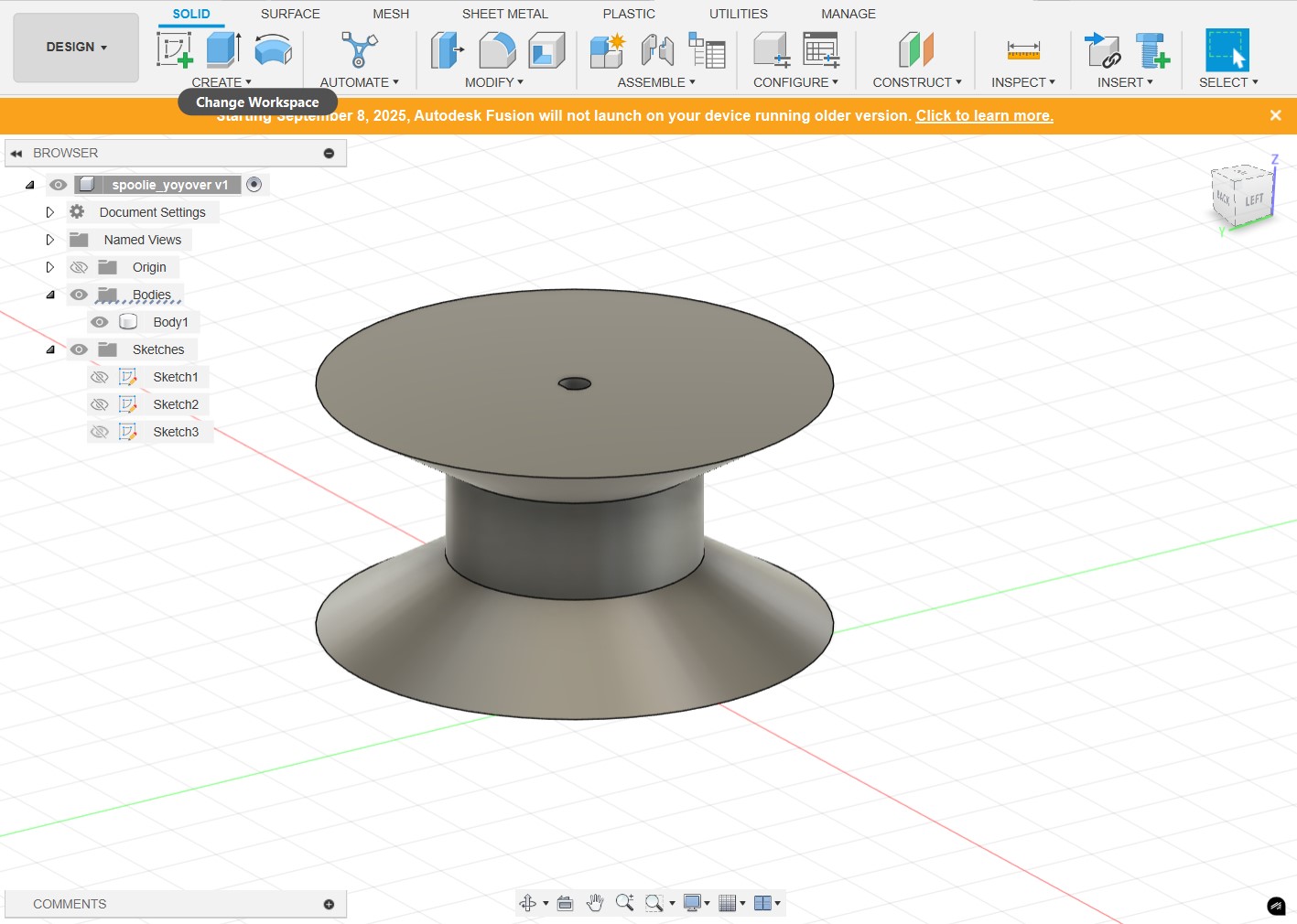
Unfortunately, we didn't end up using this design becaue it was too large for our box, and we already had the maxmimum amount of space filled up inside the box.
Box & Lid
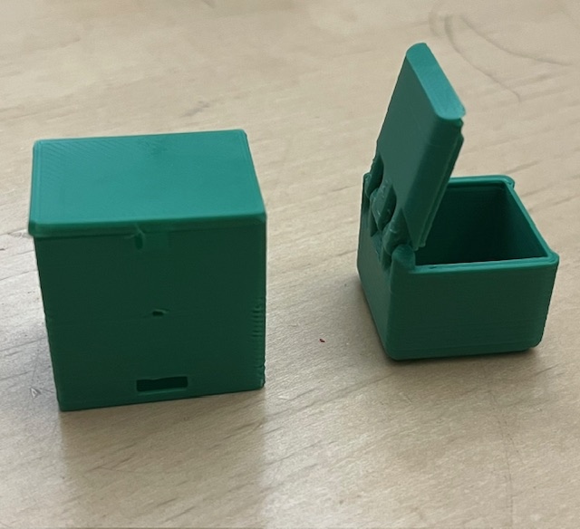
Test Boxes
Final Box
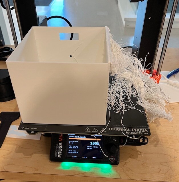
We designed and constructed a box for the machine's housing, you can check Gillian's documentation for more details on this section. We designed one that had the lid attached with a latch and the other is a hinged box design we found on Thingiverse by povsky. The group decided that they liked the hinged box better, so we edited the file to have holes for the string and the sensor. However, when trying to make a full sized 3D print, the first one stopped 25% through and the second one the box printed by the lid became spaghetti. To save time and reduce waste, we decided to just use the second box and do something else for the lid.
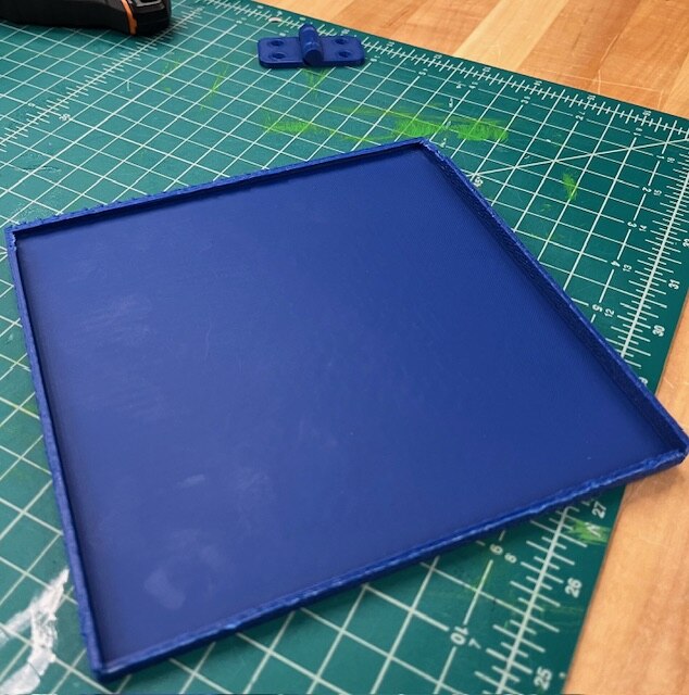
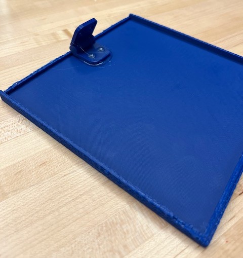
For the lid, we decided to make a shoebox style lid. The plan was to have to fit snugly over the box to stay on. Amazingly, the print for the lid failed and one of the sides was a bit spaghetti-ed. Once again in the name of time and waste reduction, we once again decided to pivot. Using a soldering iron, we put two holes on one side of the lid and two holes in the box to attach them with a hinge. After breaking the hinge, we made a zip tie “hinge” to attach the lid.
Files
Designing the Spider
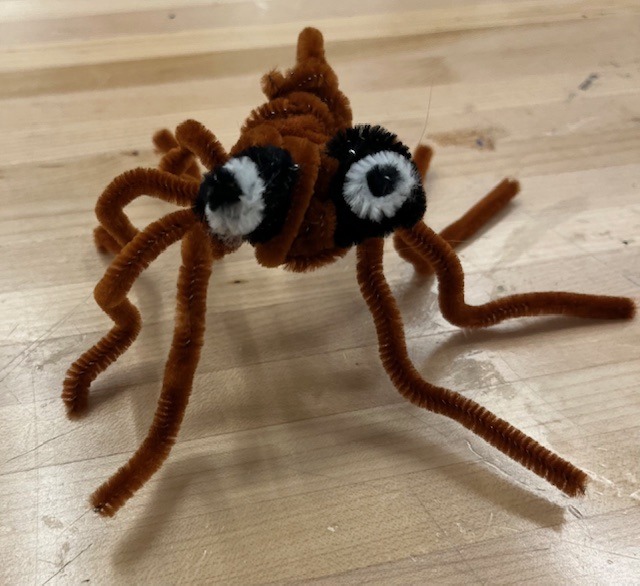
The process for designing the spider was incredibly simple and required very little effort. We took pipe cleaners and wrapped them around each other to make a body, then we took a small amount of glue and used it to attach the eyes. Say hi to Fil the Spider! Fil is a very mean spider who loves to scare people. His favorite food is nachos with flies.
The Hook
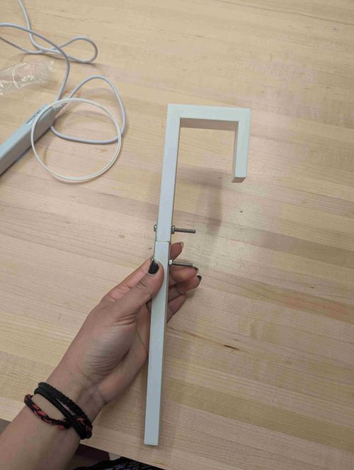
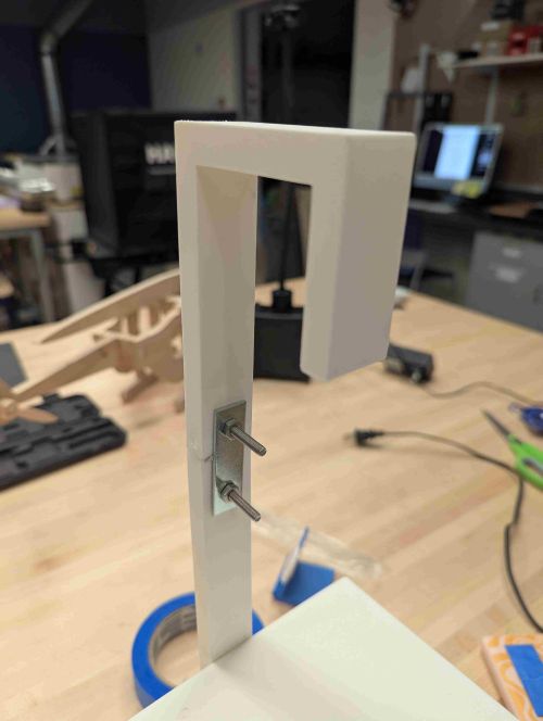
The hook was made on Onshape, the measurements were taken of the support beam that we are going to hang it off of. It was 2 inches by 2 inches, so when it was being made, we made sure the inside was at least 2 inches, but we made it a bit bigger so there was room for it actually to fit around the beam.
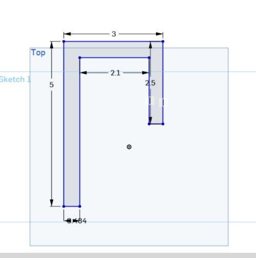

One issue that came up was the hook not being long enough to fit on the beam and hold the box. We were limited by the size of the 3d printer plate, so we made an extension. We took the width of the original hook and made it the same as the extension, then we made it 7 inches long so that there was enough space. The hook and the extension are connected through brackets, which we made a hole in by soldering through the PLA and using a nut and bolt to hold it in place.