Group Documentation: Week 6, group 1 (Tammi, Gillian, Hanna, Sierra S.)
Electronics Design
Measuring Currents & Voltage
The Astro AI digital multimeter is used to measure voltage, current and resistance in electronic devices and circuits. It has practical use for testing electrical outlets, testing appliances, extension cords and for testing batteries. It can also identify if the correct voltage is being used, and can help diagnose and debug broken connections or faulty components.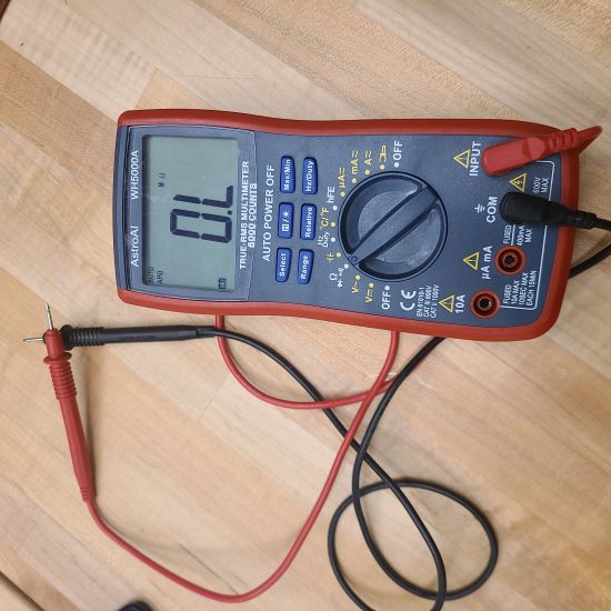
First we connected the probes to the multimeter, one red and one black. The black probe gets connected to the "com" jack and the red cable gets connectiong to the jack that is label "V" or "+". The table below shows some of the symbols that can be found on the multimeter's selection dial. It was obtained from The Spruce.Com. We turned the selector knob to read the voltage in Ohms. Once touching the two probes to metal in the circut, or for instance the ends of the battery, the voltage will display on the screen. The picture below shows the reading from a 5 Volt circuit.

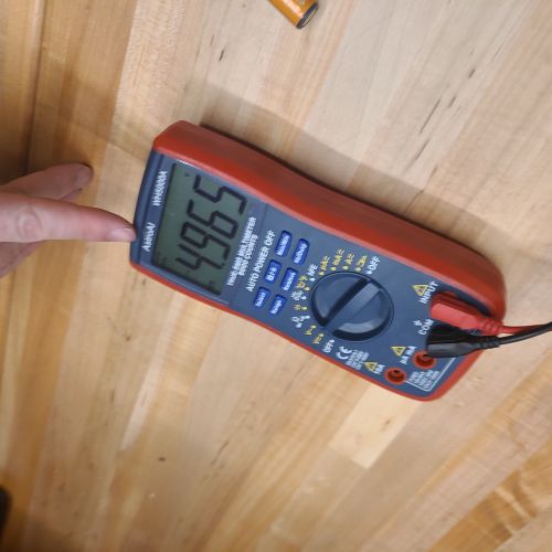
The Astro AI digital multimeter was essential for measuring different aspects of our circuits, including voltage, current, and resistance. On the multimeter's dial, the _ symbol represents direct current (DC), which is used for most electronic circuits, while the ~ symbol stands for alternating current (AC), used for outlets and larger power systems. Understanding these symbols helped us accurately configure the multimeter to test various points in the circuit. For example, when measuring DC voltage, we connected the probes across the component terminals and adjusted the selector knob accordingly. This allowed us to monitor voltage drops and ensure that components like LEDs were receiving appropriate power.
Experiments with the Astro AI WH5000A Digital Multimeter
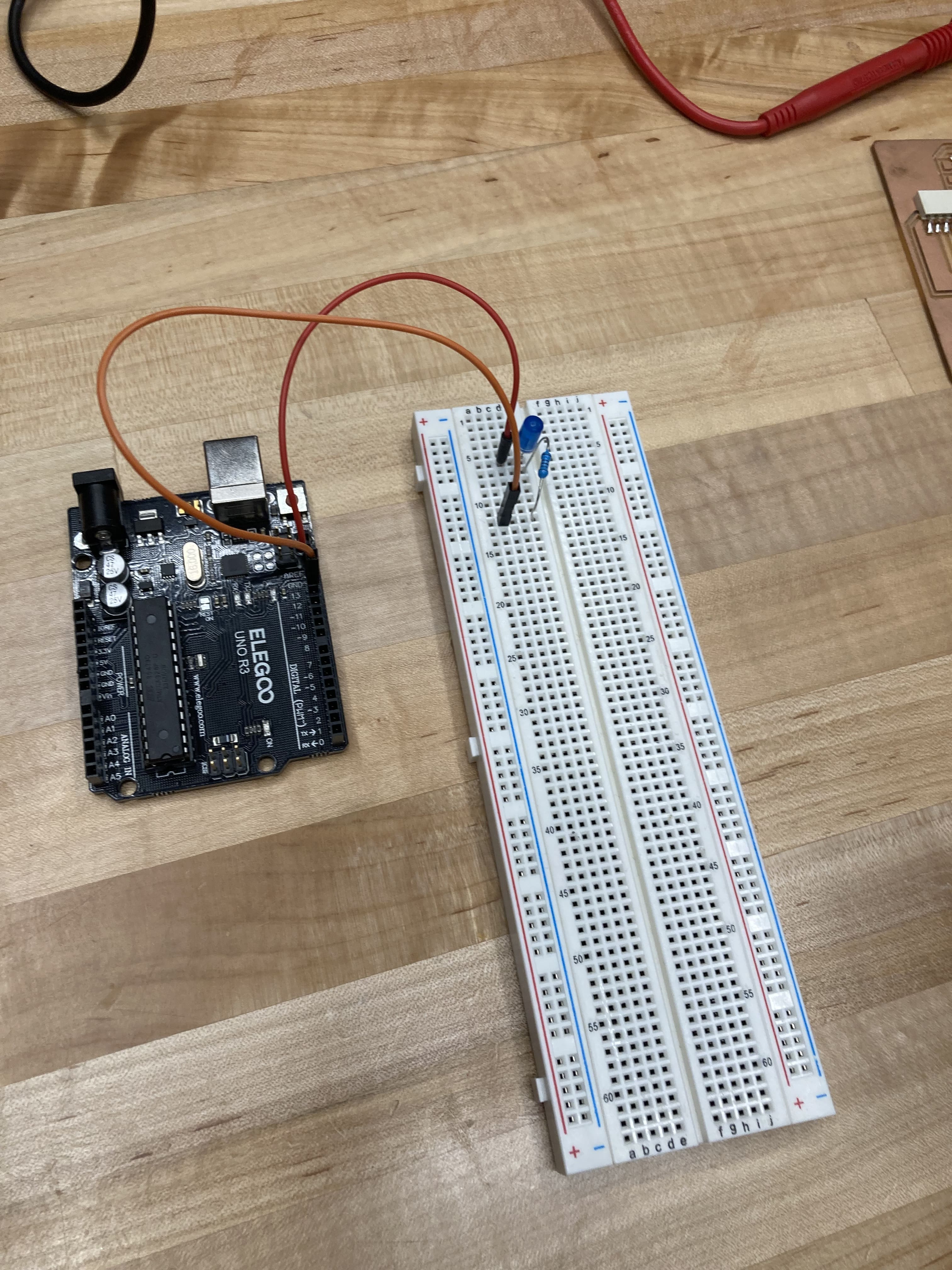
We used our digital multimeter to experiment with red and blue LEDs. The supplies we used included a breadboard, a 1000 Ohm resistor, blue and red LED lights, and ground wire. We set the circuit up in the same way we had in the Wokwi simulator in the previous week however this time we were able to use a breadboard and real components. Once the circuit was set up we could test the forward voltage of each segment of the circuit. Our results are in the sketches and tables below and a few short videos showing the red and blue LEDs blinking.
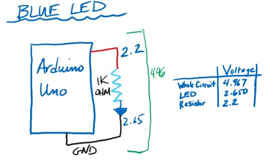
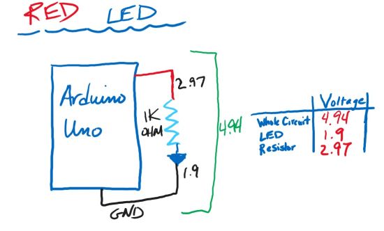
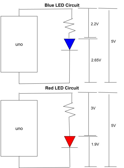
The video below shows the difference in voltage when the LED is turned on vs. when the LED is turned off in our circuit. The probes are attached to the ends of the jumper wires for pin 13 & GRND. This represents the total voltage of the circuit, which is about 5 volts, as shown in the diagram above.
The resistance in measured in ohms of the resistor. This does not relate to anything shown in the above diagram, as this is a measure of ohms.
-min.jpg)
The Circuit
We used a simple blinking light circuit with a pin 13 & GRND connection, one LED (voltage of LED varies by color), and a 1K ohm resistor.
Understanding Resistors and Current Flow
In our experiments, we observed how resistors influence current flow in a circuit. A resistor acts like a valve, controlling how much "water" (or current) is allowed to flow through. Lower resistance allows more current to pass, while higher resistance restricts it. This behavior was particularly noticeable when using different resistors with LEDs. For instance, when we reduced resistance, the LED brightness increased due to the higher current flow. Additionally, when an LED is reversed in a circuit, the voltage gets trapped between the legs of the LED and the power supply, preventing current from flowing further. In this state, the voltage "chills" at the anode (the long leg of the LED), unable to escape.
The blue LED needed a higher voltage to light up than the red LED. This means that the red LED has a lower forward voltage than the blue LED. On average the voltage for red is between 1.8 and 2.2 while the blue is typically between 2.7 and 3.6. Blue light in general requires more energy so if were we to connect both the red and blue LED lights at the same time, the blue light would show slightly dimmer as there would not be enough voltage to show full brightness.
The Rigol Oscilloscope
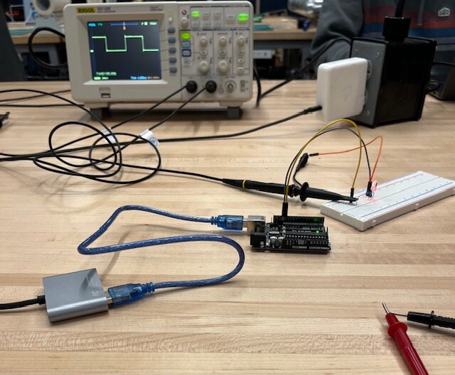
An oscilloscope displays a graph of the voltage levels of the attached circuit. It shows the waveform and frequency of the voltage. The graph shows the amount of voltage on the y-axis and time on the x-axis. To use the oscilloscope, connect both probes to opposite ends of your circuit. Both axes can be adjusted so that it works for different voltages and waveforms.
In the above circuit, an Arduino Uno was programmed to constantly turn the LED on and off with no delay in between. This made the LED look a bit dimmer since it was flashing too fast for the human eye to notice. Using the oscilloscope, we could see that the voltage was going up and down in fractions of a second. They are square waves because it is a DC power supply that is turning on and off.
The video above shows the voltage vs. time of an always-on LED where the time increments are much larger than shown in the above image. The voltage jumps so quickly that the voltage appears as a thick, shaded-in bar on the graph.
Transistors: MOSFETs vs. Bipolar Junction Transistors
We didn't use transistors in our circuit, yet Fab Academy students often implement them into their projects. While bipolar junction transistors (BJTs) were not used in our setup, we focused on MOSFET transistors due to their efficiency and ease of use. MOSFETs act like variable resistors, where the gate voltage determines the resistance level, allowing precise control of current. A key advantage of MOSFETs is their low RDS (on) and low gate voltage requirement, making it easier to switch them on and off with minimal power. This capability was particularly useful in circuits where controlling the brightness of LEDs or the operation of other components was necessary.