This week is our first machine week where we explore how to use a laser cutter and a vinyl cutter. The main tools I used were:
XTool P2SCarbon Laser Cutter andXTool F1 Ultrafor engravingCricut Maker 3and theRoland Versastudio GS2-24Vinyl Cutters
Learning Objectives
- Demonstrate and describe parametric 2D modelling processes.
- Identify and explain processes involved in using a vinyl cutter.
- Identify and explain processes involved in using a laser cutter.
- Develop, evaluate, and construct a parametric press-fit construction kit.
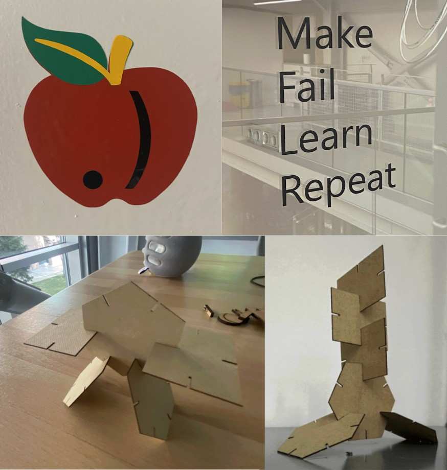
Hero Shot
Vinyl Cutting
Cricut Maker 3
1) Creating the Design
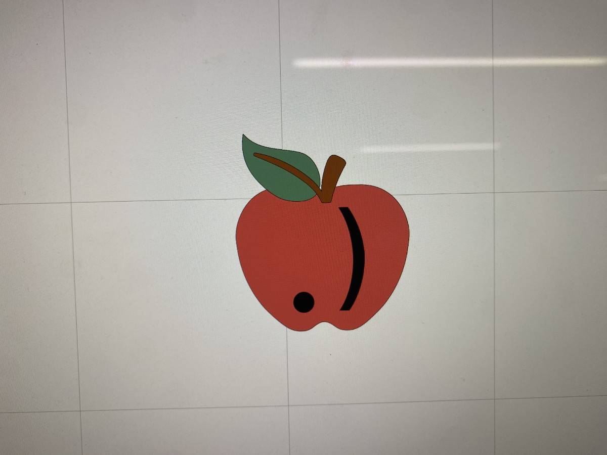
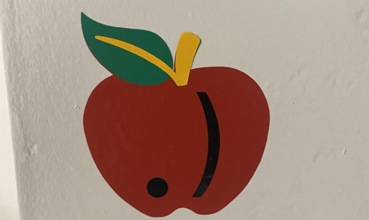
Firstly, I connected a Mac to the Cricut Maker 3 and opened the Cricut Design Space app. Then I created my design using on a blank canvas. I designed an apple with a custom .) on it which is the symbol of our FRC Team at our Fablab #6431.
The apple was imported from the app and the .) was added as a text layer on top of the apple.
Design:
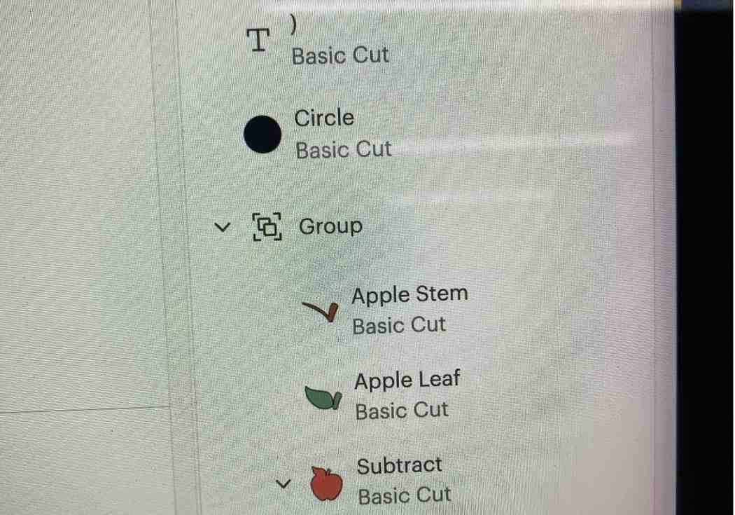
Layers of the Design:
My design consisted of 4 separate layers, each to be cut from a different vinyl color.
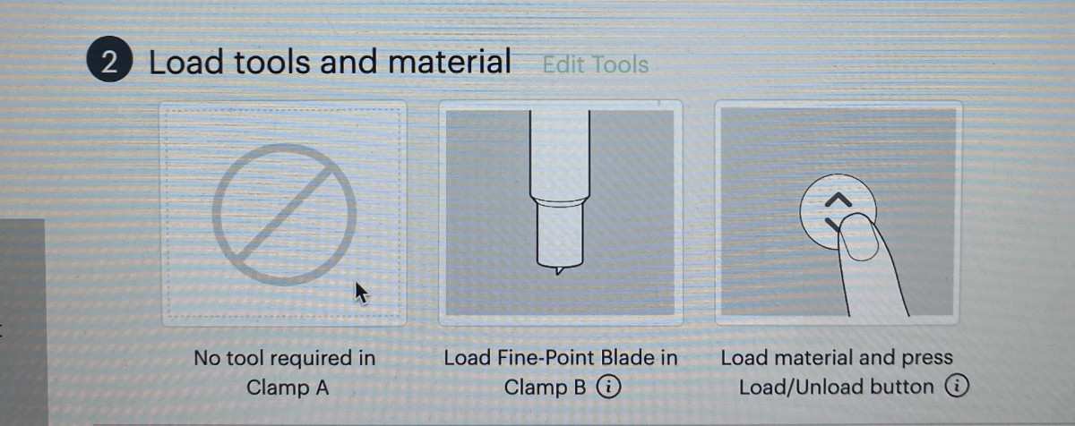
2) Cutting the Vinyl
To cut the design, I followed these steps:
Placed the vinyl sheet on the Cricut cutting mat.
Used a roller to press down the vinyl sheet to ensure there were no air bubbles.
Loaded the mat into the Cricut Maker 3.
Selected the correct material settings in Design Space.
Pressed “Make It” to start the cut.
Because my design had 4 layers, I repeated this process 4 times with different vinyl sheets.
Here are the instructions shown on the app:
Process video (2x speed):
3) Final Sticker
After cutting all 4 layers, I carefully weeded the extra vinyl and aligned the layers together. The final result was a multi-layer vinyl sticker of our apple + .) FRC team logo.
GS2-24
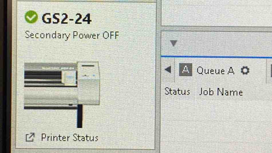
I also tested the Roland VersaSTUDIO GS2-24 vinyl cutter, which is more industrial-grade compared to the Cricut Maker 3. This machine is capable of cutting larger rolls of vinyl at higher precision and speed, making it suitable for professional sign-making and graphics applications.
Setting Up the Machine
I loaded the vinyl roll into the GS2-24 and aligned it using the adjustable pinch rollers. The machine automatically detected the roll width. On the connected computer, I used Roland CutStudio software to prepare the design file. In Roland CutStudio select the GS2-24 machine.
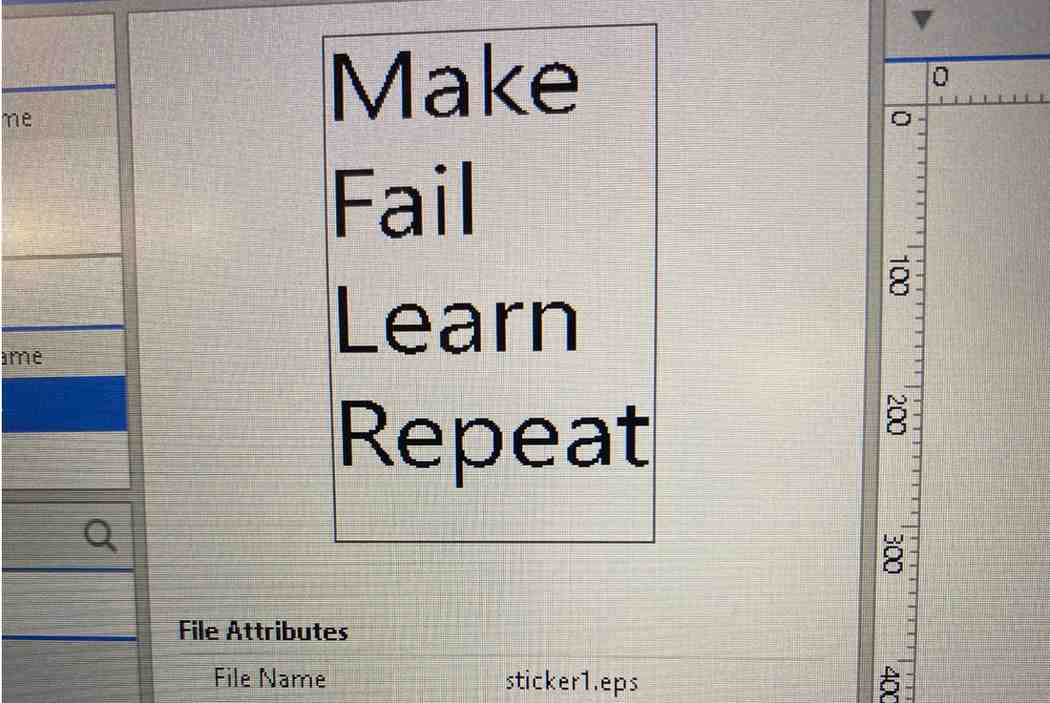
I then loaded the design file and aligned the text for the machine. Final design:
Then I cut the design. Process of cutting (4x speed):
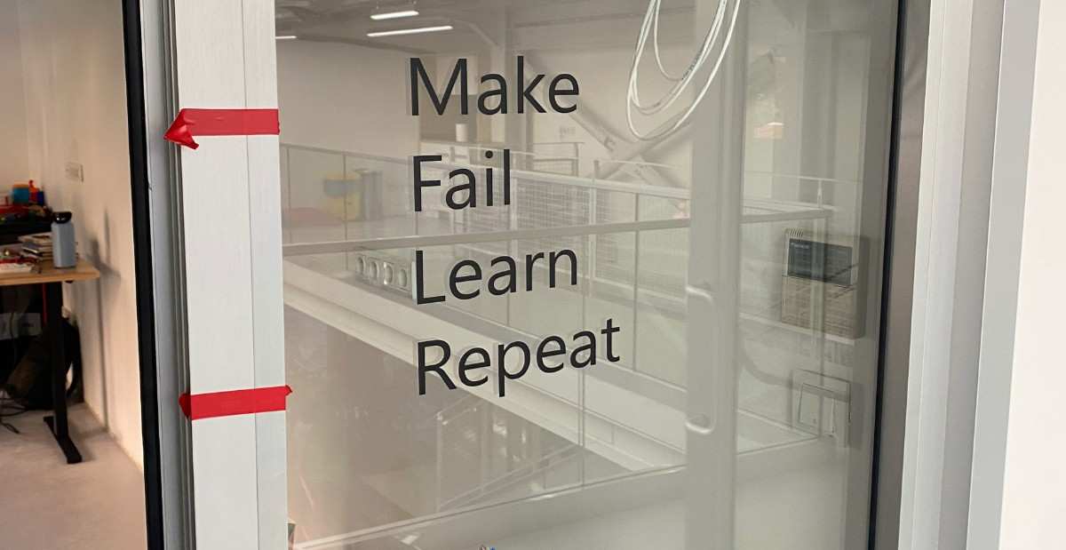
I then used transfer tape to transfer the sheet to the glass wall in our Fablab. Final sticker:
Laser Cutting
Construction Kit
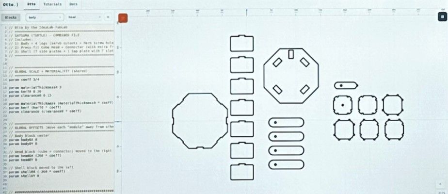
To design the parametric construction kit I used Otto: a comprehensive 2D design tool which equipped with it’s own DSL (Domain Specific Language) which was developed by me and other students here at our Fablab. Github link of the project:
https://idealab-design-environments-group.github.io/Otto/
Design using Otto:
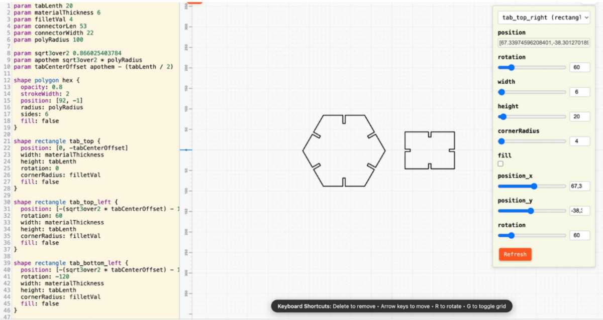
Through Otto users can design parametrically using block-based, text-based or direct canvas interaction modalities. There are many parameters used for the construction kit that can be seen on the left side of the Otto editor above. I exported the design in SVG format using Otto and sent the design over to the Mac connected to our xTool P2S Laser Cutter.
Before cutting, I designed a parametric construction box using Otto’s domain-specific language (DSL) and visual editor. The goal was to create a modular and reusable design that could adapt to different material thicknesses, sizes, and joint types simply by changing a few parameters.
Defining Parameters
In the Otto editor, I defined key parameters such as:
thickness — the material thickness, set initially to 0.8 mm
slot_width — the width of the finger joints, automatically calculated as thickness + kerf
box_length, box_width, box_height — the main dimensions of the construction box
joint_count — the number of interlocking joints per side
Each of these variables could be modified directly from the side panel in Otto, and all dependent dimensions updated instantly. This parametric setup eliminated the need to redesign when switching to a new material thickness or box size.
Modular Structure and Components
The construction box consisted of six sides: base, top, and four walls. I created the slot pattern algorithmically using Otto’s shape functions and loops, ensuring perfect symmetry and alignment.
I also added internal dividers as optional components, controlled by a Boolean parameter (has_dividers = true/false) and adjustable in number. When enabled, these dividers automatically resized to fit the current box dimensions.
Advantages of Parametric Modeling
This approach allowed me to: Instantly adjust the box dimensions for different materials or laser settings.
Automate kerf compensation through calculated offsets in the joint pattern.
Reuse the same design to create boxes of varying scales for other projects.
Test modular assembly by changing joint parameters and simulating different fits.
For example, when I switched the material thickness from 0.8 mm wood to 3 mm acrylic for a test cut, the design automatically recalculated all slot widths, ensuring the parts still fit perfectly
I cut the design on a wood material with a thickness of 0.8 mm (I adjusted the thickness parameter for the design based on this value) and at a power of 45% and a speed of 20. I selected the cut method on the software to cut the pieces.
Below is a photo of the final cut design:
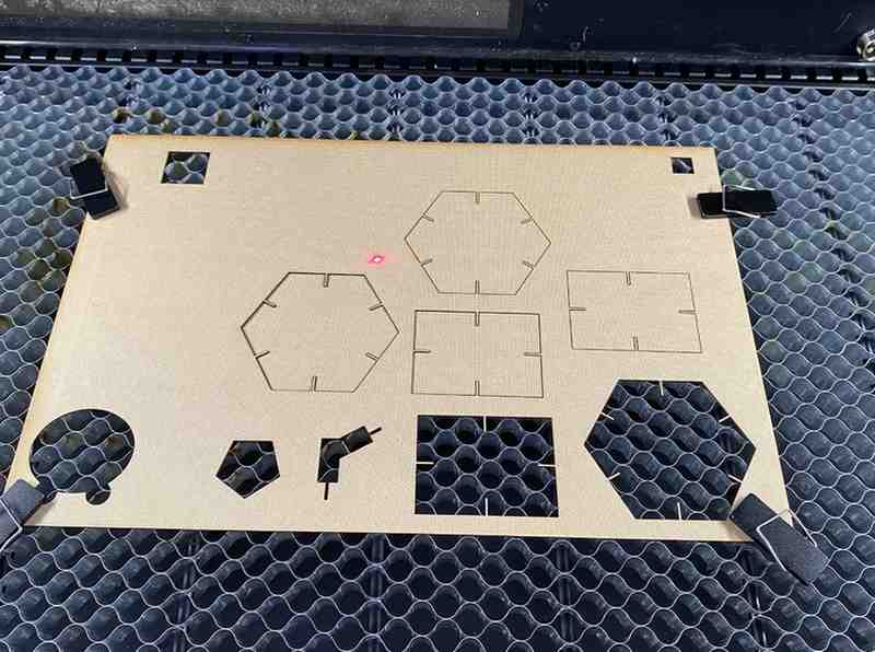
XTool P2S Laser Cutter
And below is a video of the process of cutting:
Fabrication Parameters
Material: 0.8 mm wood
Power: 45 % Speed: 20
Cut Mode: Vector cut
I cut my design successfully on my first attempt because I used pre-set power and speed values that were safe so no materials got burned.
I calculated the average kerf of 0.23 mm by measuring three kerfs of 0.20 mm, 0.27 mm and 0.23 mm.
The intended measure in the part is 66.57 mm. The cut piece’s measurement is 66.37 mm so a kerf of 0.20 mm is present. The intended measure in the part is 53.27 mm. The cut piece’s measurement is 53 mm so a kerf of 0.27 mm is present. The intended measure in the part is 51.20 mm. The cut piece’s measurement is 50.97 mm so a kerf of 0.23 mm is present.
This measured kerf value was directly used in the parametric slot width calculation inside Otto, allowing the joints to be adjusted automatically without redesigning the geometry.
The final constructed parametric construction kit can be seen below using two different assembly methods.
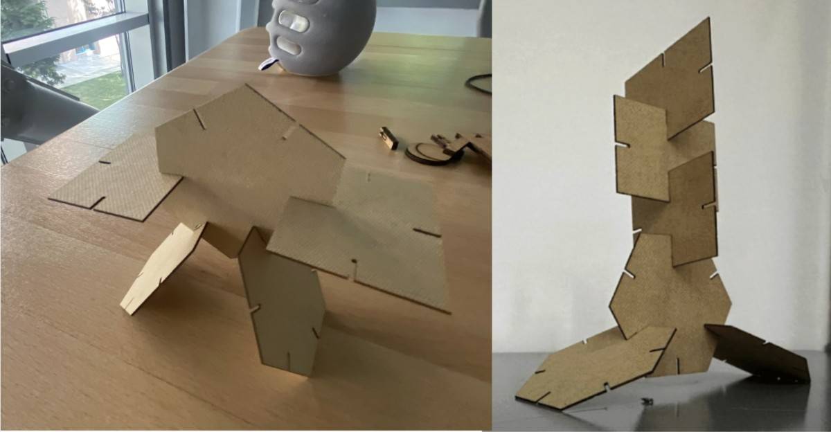
Non-flat Construction
Although the individual parts are laser-cut from flat stock, the final shell assembly forms a three-dimensional structure through press-fit joints and angular geometry, resulting in a non-planar assembled object.
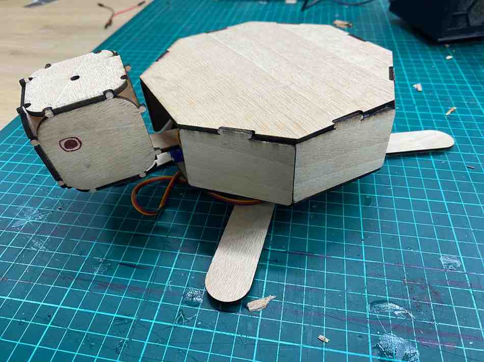
Satsuma
Building on the parametric logic and press-fit principles developed in the construction kit, I extended the same workflow to a more expressive and geometry-driven object: Satsuma. While the construction kit focused on modularity, reusability, and orthogonal box geometry, Satsuma served as a controlled experiment in applying parametric press-fit design to non-rectilinear, radial forms. This transition allowed me to reuse the same core parameters—material thickness, kerf, clearance, and scaling—while introducing angular assemblies, curved geometry, and shell-like structures. By doing so, I tested whether the parametric strategies validated in the construction kit could reliably scale to more complex assemblies without glue or fasteners, reinforcing the robustness and flexibility of the design approach.
1) What I designed
I modeled a shell-only assembly made from:
- 1 top plate (octagon)
- 7 side plates (rectangles), each with one tab
- The top plate has 7 slots that match the side-plate tabs
The tabs slot into the top plate so the shell can be assembled without glue.
I designed this satsuma using Otto as I mentioned in my construction kit. The otto code files can be found in the file zip at the bottom of this page.
On Otto interface:
2) Parametric controls (important parameters)
The design is controlled mainly by these parameters:
coeff = 3/4
Scales the whole design while keeping proportions consistent.Press-fit fit parameters
materialThicknesskerfclearanceslotW = materialThickness + clearance - kerf
This makes the slot slightly larger than the material thickness (adjusted by kerf + clearance) so the tabs press-fit reliably.
- Tab sizing
tabSpansets tab widthtabDepth = materialThicknessTab height is exactly the material thickness so it matches the slot depth and creates a clean press-fit.
3) Geometry decisions
Top plate
- Built as an 8-sided polygon:
bodySides = 8bodyRcontrols overall sizebodyRot = 22.5aligns the octagon cleanly
Side plates
- Each side plate is a rounded rectangle with:
- height =
shellH - width =
sidePlateLen(derived from octagon geometry)
- height =
- Each plate has a single centered tab (unioned onto the rectangle)
- All side plates are offset in X using:
sidePlateOffsetXso they don’t overlap with the top plate in the cutting layout.
Slots on the top plate
- 7 slots are placed around the top plate using an apothem-based radius:
slotCenterR = apothem - tabDepth/2
- Slots are rotated to match the plate edges (45°, 90°, 135° …) and removed using a
difference.
How to Fabricate (quick)
- Set your material and fit values (
materialThickness0,kerf0,clearance0) - Adjust
coeffif you want the shell larger/smaller - Export the design as a vector file (SVG/DXF depending on your workflow)
- Laser cut and test-fit
- If too tight → increase
clearance0slightly - If too loose → decrease
clearance0or slightly increasekerf0(depending on measurement)
- If too tight → increase
Laser Engraving (xTool F1 Ultra)
As an additional exploration beyond flat-sheet cutting, I tested laser engraving on an existing consumer object using the xTool F1 Ultra. The goal was to understand material response, parameter tuning, and safe engraving limits when working with unknown industrial plastics.
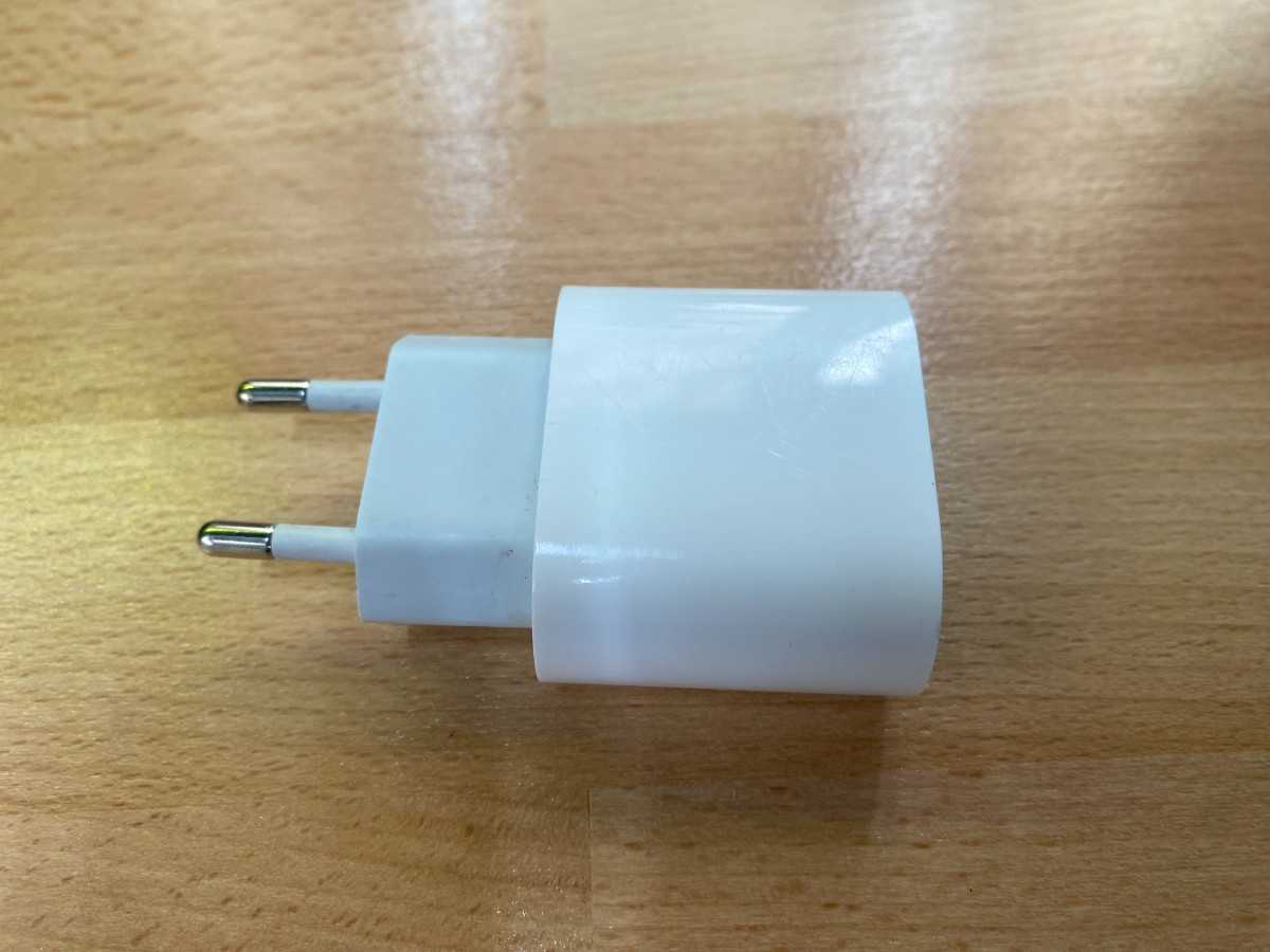
Object Selection
I chose a USB-C iPad charger head, which is typically made from PC/ABS plastic. This material is electrically insulating and heat-resistant but requires careful parameter tuning to avoid surface melting.
Initial State
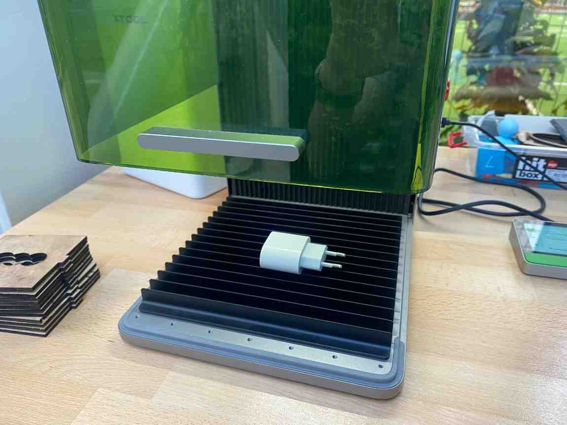
Before engraving, I documented the object and setup:
- Charger head before any operations
- xTool F1 Ultra connected to a Mac
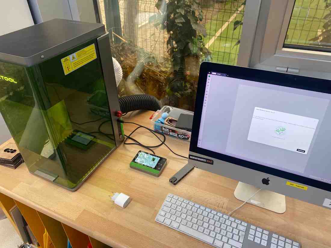
- Charger positioned flat on the engraving bed
Design & Setup
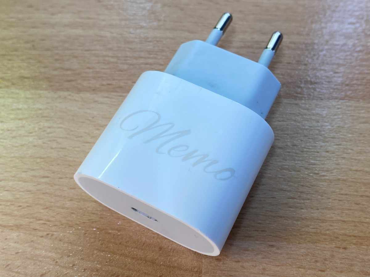
I used xTool Creative Space to prepare a simple text engraving. The text “memo” is a shortened version of my first name (Mehmet), chosen to test small typography clarity on curved plastic surfaces.
The charger surface was scanned using the F1 Ultra’s camera, and the text was aligned directly on the scanned image to ensure accurate placement.
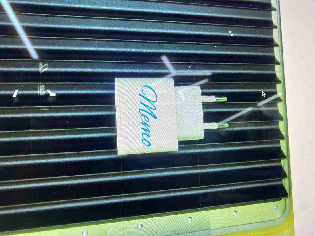
Demo Video of Machine In Use (3x Speed)
Parameter Testing & Iteration
Because the exact plastic formulation of the charger is unknown, I tested multiple engraving settings to observe surface response.
Test 1 — Low Power (Too Light)
- Power: 30%
- Speed: 200
- Frequency: 30 kHz
Result: The text was barely visible, indicating insufficient energy transfer for this material.
Test 2 — High Power (Too Aggressive)
- Power: 60%
- Speed: 200
- Frequency: 30 kHz
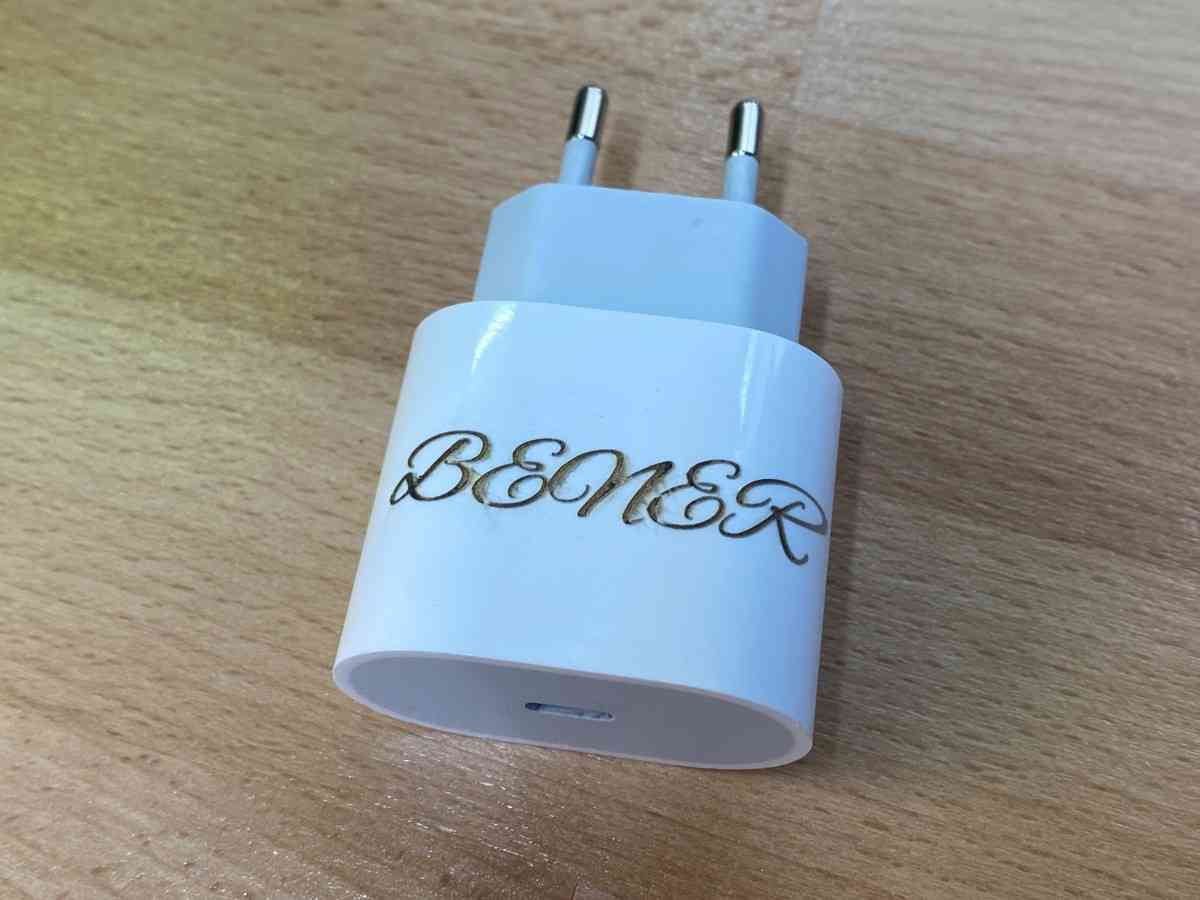
Result: The engraving was clearly visible, but the plastic surface showed signs of excessive thermal interaction, making this setting unsuitable for safe or repeatable use.
Evaluation & Optimal Range
From these two controlled tests, I concluded that:
- 30% power was too low to create a reliable surface mark
- 60% power caused unnecessary thermal stress
The optimal range for this material and speed lies around ~45% power This experiment highlights the importance of incremental parameter testing when engraving non-standard or unknown materials.
Key Takeaways
- Laser engraving is not limited to flat stock, existing objects can be engraved safely with proper tuning
- Industrial plastics require calibration passes, not preset reliance
- The xTool F1 Ultra’s camera-based alignment is especially useful for engraving pre-manufactured objects
- This extra test extended my understanding of laser–material interaction beyond sheet cutting and reinforced the importance of process documentation and parameter justification.
Group Project
You can check our group project here