Learning Objectives
- Implement programming protocols.
1. Introduction
This week, the objective was to explore the microcontroller datasheet, understand its capabilities, and then write and simulate a program that interacts with local input devices and communicates with a remote device through a wired or wireless protocol.
For this assignment, I used the ESP32-C3 Super Mini, built around a RISC-V core.
My program reads four push buttons and communicates the button state to my computer via USB serial, which qualifies as a remote wired communication interface.
2. Browsing My Microcontroller Datasheet
The ESP32-C3 is a compact RISC-V microcontroller featuring:
- 3.3 V logic level
- Multiple GPIO pins configurable as digital I/O, ADC, I²C, SPI, PWM, or UART
- Built-in USB-Serial interface (UART over USB)
- Low power consumption modes
- Wi-Fi (2.4 GHz) and Bluetooth LE support
Below is the pinout diagram I used:
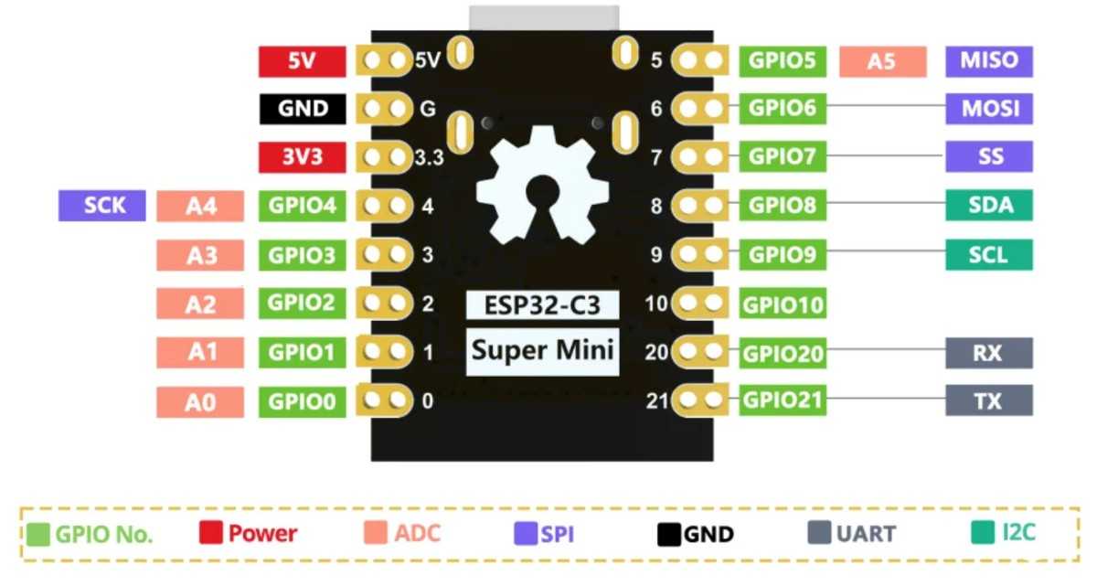
Figure 1. ESP32-C3 Super Mini pinout diagram. Source: ICBBuy Wiki, “ESP32-C3 Mini Development Board.” Available at: https://wiki.icbbuy.com/doku.php?id=developmentboard:esp32-c3mini (accessed 18 February 2026).
Key things I learned from the datasheet
- GPIO pins can be reconfigured into different peripheral modes (SPI, UART, I²C, PWM).
- GPIOs support internal pull-up resistors, which is perfect for button inputs.
- The USB-Serial interface is always available for debugging/communication.
- All logic levels are 3.3 V, making it safe for many sensors and displays.
- Several pins (GPIO4–7, 10) support SPI, which I will later use for my OLED display.
This information was essential for planning my wiring and programming.
3. My Wiring Plan
For this week’s assignment, I focused on four push-buttons connected to the ESP32-C3, which act as local input devices.
I later plan to use the OLED display, but for this week, only the buttons were required.
Push Button Connections
| Button | ESP32-C3 Pin | Function |
|---|---|---|
| BTN1 | GPIO2 | Input + Pull-Up |
| BTN2 | GPIO3 | Input + Pull-Up |
| BTN3 | GPIO4 | Input + Pull-Up |
| BTN4 | GPIO5 | Input + Pull-Up |
Each button is connected between its GPIO pin and ground.
The ESP32-C3 internal pull-ups keep the pin HIGH when not pressed, and LOW when pressed.
Why this meets the assignment criteria
- Buttons = local input interaction
- Serial output = remote wired communication
- Simulation/programming = microcontroller workflow
- GPIO analysis = datasheet usage
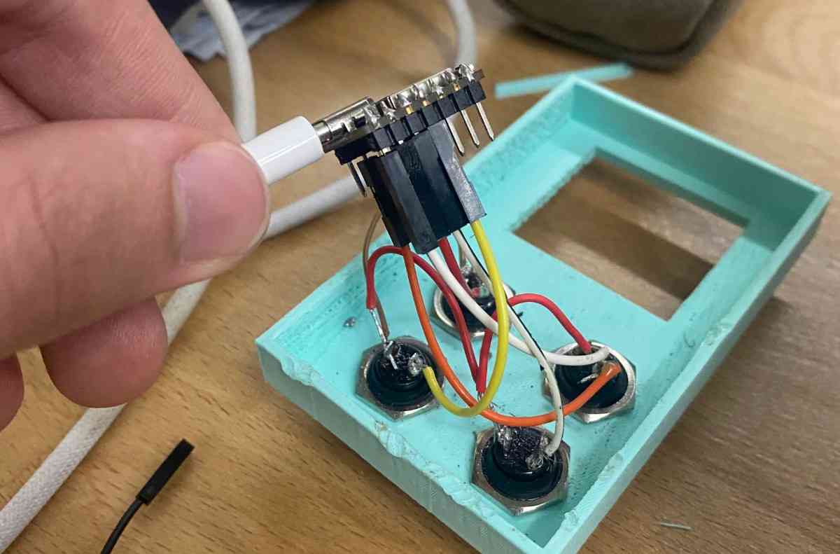
Finished Wiring
4. Programming the ESP32-C3
I wrote a program in the Arduino IDE in C++ that:
- Reads all four buttons
- Detects a new press event (edge detection)
- Uses debouncing
- Prints which button was pressed over USB serial
This communicates with a remote wired device (my laptop) using UART-over-USB.
Why I Chose Arduino IDE
I selected the Arduino environment because:
- It provides fast prototyping and very readable code.
- The ESP32-C3 boards have excellent Arduino core support.
- Serial communication, GPIO input, and debounce logic are straightforward.
- I could quickly test button logic without a complex build system.
- It integrates well with the USB-Serial bridge on the ESP32-C3.
Source Code
// ESP32-C3 Button Option Selector
// GPIO2 → Option A
// GPIO3 → Option B
// GPIO4 → Option C
// GPIO5 → Option D

int buttons[] = {2, 3, 4, 5};
const char* labels[] = {"Option A", "Option B", "Option C", "Option D"};
int lastState[4];

void setup() {
  Serial.begin(115200);
  delay(500);
  Serial.println("\nESP32-C3 Option Button Test");
  Serial.println("Press any button (GPIO 2–5)...\n");

  for (int i = 0; i < 4; i++) {
    pinMode(buttons[i], INPUT_PULLUP);
    lastState[i] = HIGH; // not pressed
  }
}

void loop() {
  for (int i = 0; i < 4; i++) {
    int current = digitalRead(buttons[i]);

    // Detect new press (HIGH → LOW)
    if (current == LOW && lastState[i] == HIGH) {
      delay(10); // debounce
      if (digitalRead(buttons[i]) == LOW) {
        Serial.print(labels[i]);
        Serial.println(" pressed!");
        lastState[i] = LOW;
      }
    }

    // Update when released (no print)
    if (current == HIGH && lastState[i] == LOW) {
      lastState[i] = HIGH;
    }
  }
}
The program is structured around a clean and scalable multi-button input system using arrays and state tracking. First, two parallel arrays are defined: buttons[] stores the GPIO pin numbers (2, 3, 4, 5), and labels[] stores the corresponding text messages for each button. This design avoids repetitive code and makes the program easily extendable if more buttons are added later. A third array, lastState[], stores the previous reading of each button so the program can detect state changes.
In setup(), the Serial communication is initialized at 115200 baud to enable USB-UART communication with the computer. A short delay ensures stable startup before printing the header messages. Then, each GPIO pin is configured as INPUT_PULLUP, which activates the ESP32-C3’s internal pull-up resistors. This means the default state of each pin is HIGH (3.3 V), and when the button is pressed (connected to ground), the state becomes LOW. This wiring method prevents floating inputs and eliminates the need for external resistors. Each button’s lastState is initialized to HIGH because the buttons start in the unpressed condition.
Inside the loop(), the program continuously scans all four buttons using a for loop. For each button, it reads the current digital state using digitalRead(). The key logic is edge detection, meaning the program only reacts when a button transitions from HIGH (not pressed) to LOW (pressed). This prevents continuous printing while the button is being held down. When a new press is detected, the program waits 10 milliseconds to debounce the signal. After the delay, it checks the pin again to confirm the press is valid. If confirmed, it prints the corresponding label via Serial and updates lastState to LOW.
The second conditional block detects when the button is released (LOW → HIGH transition) and updates lastState accordingly, but it does not print anything. This ensures the system is ready to detect the next press cleanly.
Programming Protocols Used
- Digital input scanning
- Hardware pull-ups
- Software debouncing
- Serial communication
(UART over USB → remote wired communication)
Problems I Faced
1. Button Bouncing
Symptom: Pressing once would sometimes print the label two or three times.
Cause: Mechanical switches physically bounce when pressed.
Fix: Added delay(10) which eliminated bounce events. Added edge detection (HIGH → LOW) instead of continuous prints.
2. False Triggers
Symptom: Sometimes a button “pressed” message appeared without touching anything.
Likely Cause: Noisy floating values read during transitions Internal pull-ups not yet engaged (startup stage) Loose breadboard connection
Fix: Set all pins as INPUT_PULLUP Added startup delay of 500 ms Ensured wires were firmly seated
5. Testing & Demo
Below is the demo video showing the buttons working and the serial messages printing when each button is pressed:
This confirms that the microcontroller:
- interacts with local input devices
- communicates with a remote wired device (my computer)
6. What I Learned
- How to use the ESP32-C3 internal pull-up resistors
- How to read button states reliably
- Using UART serial prints for debugging and communication
- How to debounce buttons in software
- Understanding pin multipurpose functionality from the datasheet
- How to implement edge detection (state change detection)
- How to structure a clean embedded program for multiple inputs
7. Group Project
You can check our group project here