This week focuses on additive manufacturing and understanding what kinds of geometries are uniquely enabled by 3D printing.
For this assignment, I completed the 3D printing portion by designing and printing an object that cannot be easily produced using subtractive manufacturing methods.
Learning Outcomes
- Identify the advantages and limitations of 3D printing
- Apply design methods and production processes to show your understanding of 3D printing.
- Demonstrate how scanning technology can be used to digitize object(s)
3D Printing
1. Introduction
Additive manufacturing allows the creation of internal geometries, moving parts, and enclosed features that are impossible or extremely difficult to achieve with subtractive processes such as CNC milling or laser cutting.
For this week, I designed and printed a sphere trapped inside a structural frame, where the internal sphere is fully enclosed yet free to move. This object is a classic example of a geometry that cannot be manufactured subtractively, as the internal sphere would be inaccessible to cutting tools.
2. Design Process
Concept Overview
The object consists of:
- A spherical ball suspended inside
- A top and bottom polygonal frame
- Multiple vertical columns connecting the two frames
- Fully enclosed geometry after printing
The internal sphere is printed in place, without assembly, and remains free to rotate and move once supports are removed.
This design demonstrates:
- Internal cavities
- Non-assemblable moving parts
- Gravity-independent fabrication
Why This Cannot Be Made Subtractively
A subtractive process would fail because:
- The sphere is fully enclosed after fabrication
- There is no tool access path to carve or insert the sphere
- Assembly after machining is impossible
Only layer-by-layer additive manufacturing makes this geometry feasible.
Designing on Onshape
I designed the model using Onshape, a cloud-based parametric CAD tool.
Step 1 — Frame Geometry
- Created a polygon sketch for the bottom frame
- Extruded it to a fixed thickness
- Repeated the same process for the top frame
Step 2 — Structural Columns
- Sketched circular profiles evenly spaced around the polygon
- Extruded them vertically to connect the top and bottom frames
- Ensured sufficient clearance for the internal sphere
Step 3 — Internal Sphere
- Modeled a perfect sphere positioned at the center
- Verified that:
- The sphere does not intersect with columns
- The clearance is enough to prevent fusing during printing
Step 4 — Printability Check
- Checked overhangs
- Confirmed support accessibility
- Exported the final model as
.STL
This iterative process ensured the object would print successfully in one piece while maintaining internal motion.
3. Print Process
Printer & Material
| Parameter | Value |
|---|---|
| Printer | Bambu Lab P1S |
| Material | PLA |
| Slicer | Bambu Studio |
| Supports | Enabled |
| Print Mode | Single-piece print |
Support Strategy
Supports were required because:
- The internal sphere needs temporary anchoring
- Overhangs exist between the sphere and the frame
I used automatic supports, which were later removed manually.
4. Results
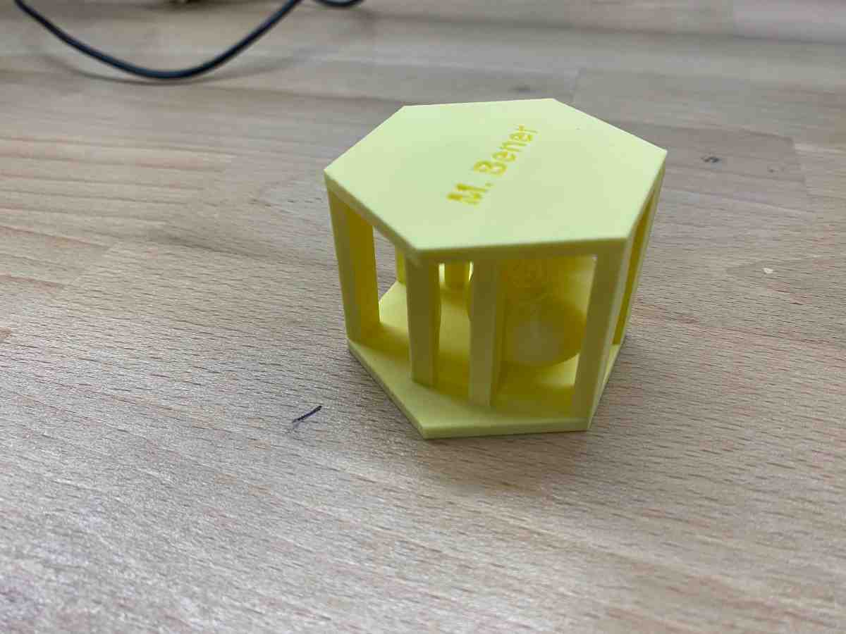
Before Support Removal
The photo below shows the print with supports still attached, straight off the printer:
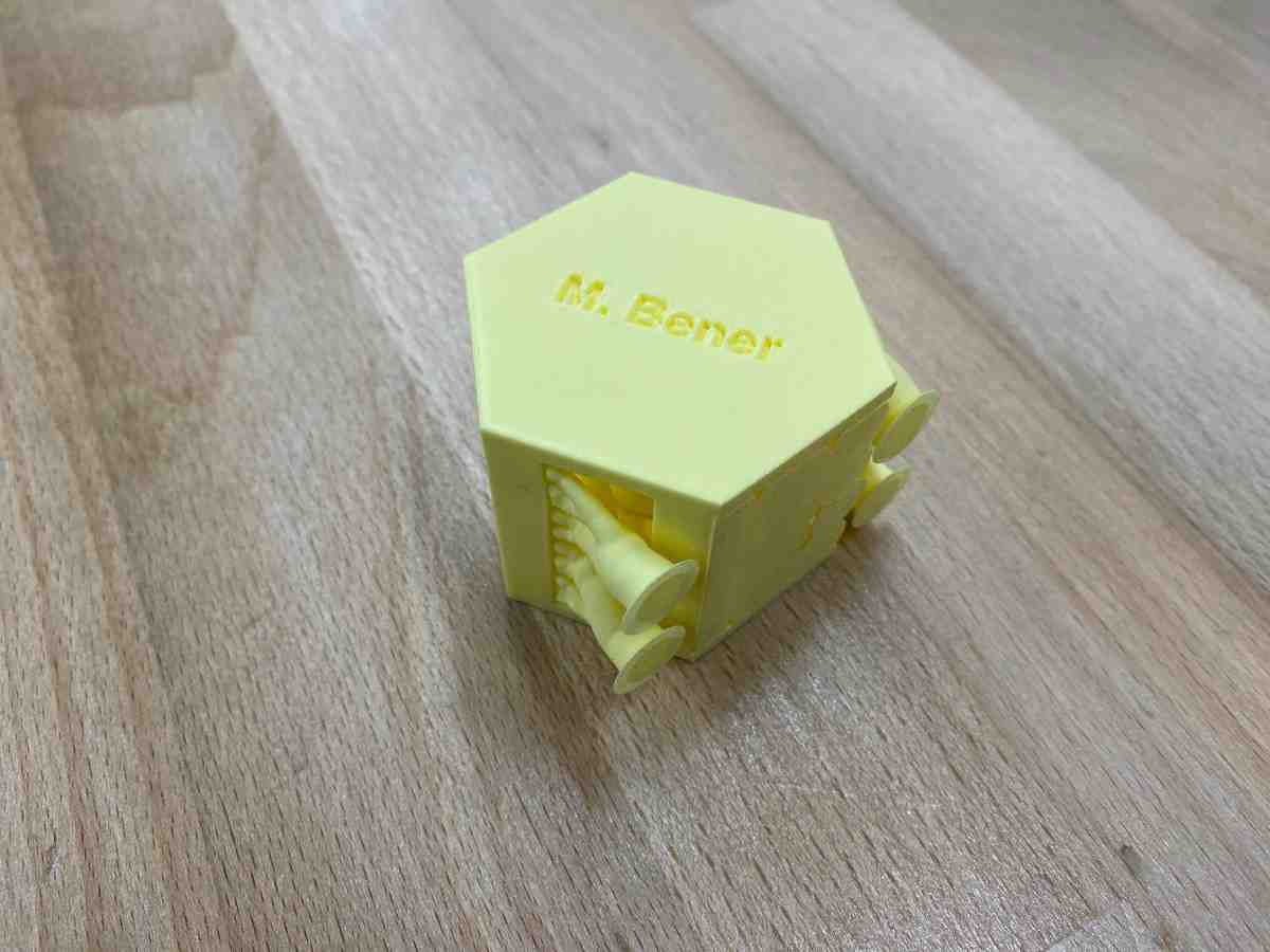
Final Print (Supports Removed)
After carefully removing the supports, the internal sphere was fully released and free to move:
Movement Demonstration
The video below demonstrates the free movement of the internal sphere, confirming that the object was printed successfully as a non-assemblable mechanism:
3D Scanning
This part of the assignment demonstrates how real-world physical geometry can be digitized using a professional structured-light 3D scanner, processed into a clean mesh, and prepared for fabrication.
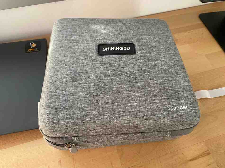
I used a Shining 3D EinStar handheld scanner to capture, process, and prepare a real object for 3D printing.
1. Hardware Setup
I used the Shining 3D EinStar, a professional handheld structured-light scanner designed for high-resolution object digitization.
Before scanning, the scanner was unpacked and connected to the workstation.
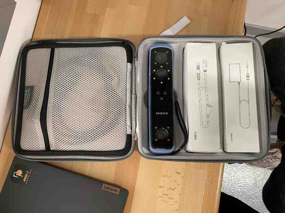
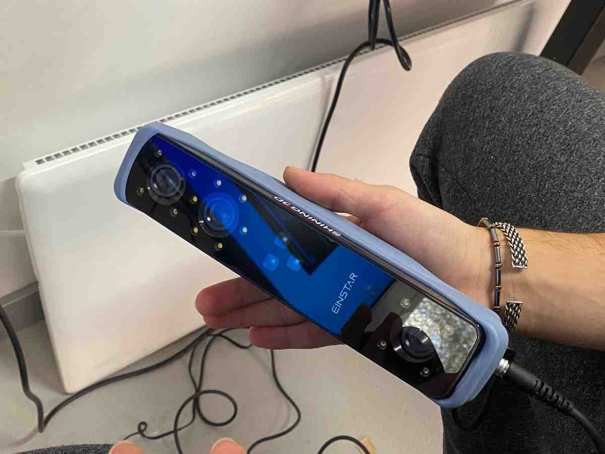
The EinStar projects an infrared structured-light pattern onto the object and reconstructs its geometry by measuring how the pattern deforms across the surface.
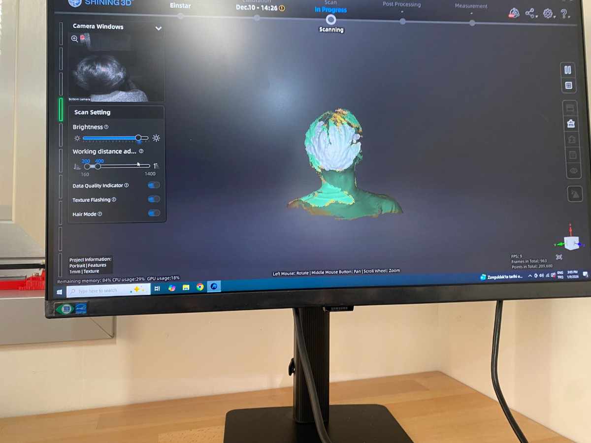
2. Live Scanning
The object was scanned by slowly moving the scanner around it while the software captured surface geometry in real time.
The scanning software displays:
- Live point cloud
- Surface reconstruction
- Coverage tracking
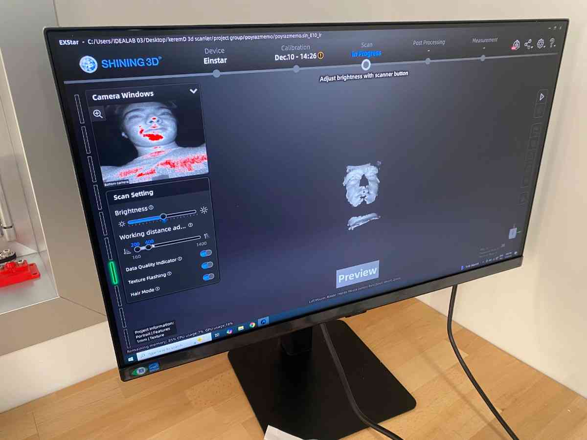
This step is critical because missing areas become holes in the final mesh, and overlapping passes increase accuracy.
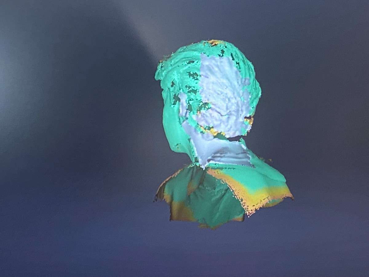
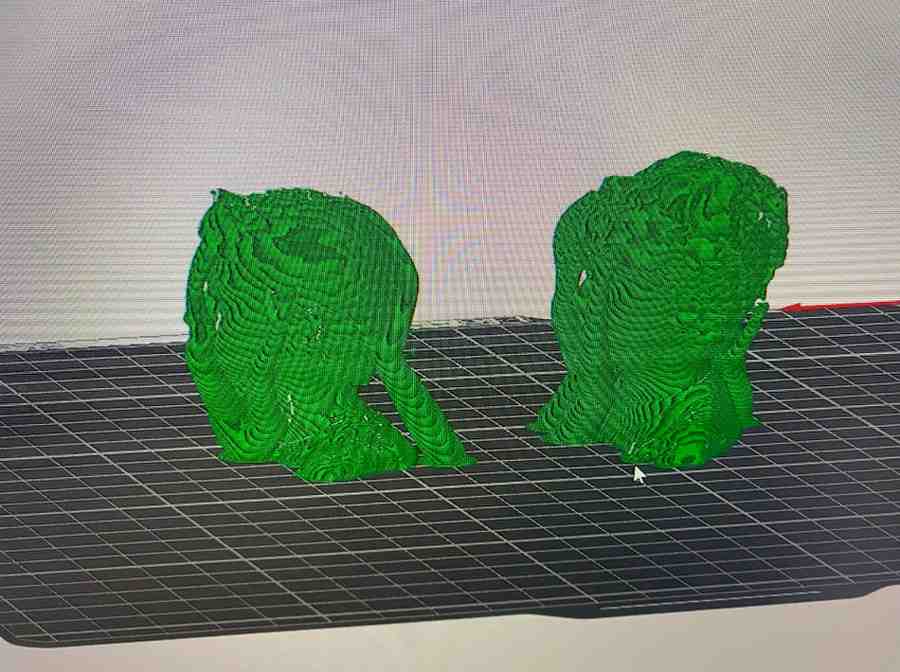
3. Raw Scan Result
After capturing all sides of the object, the software generated a complete 3D mesh.
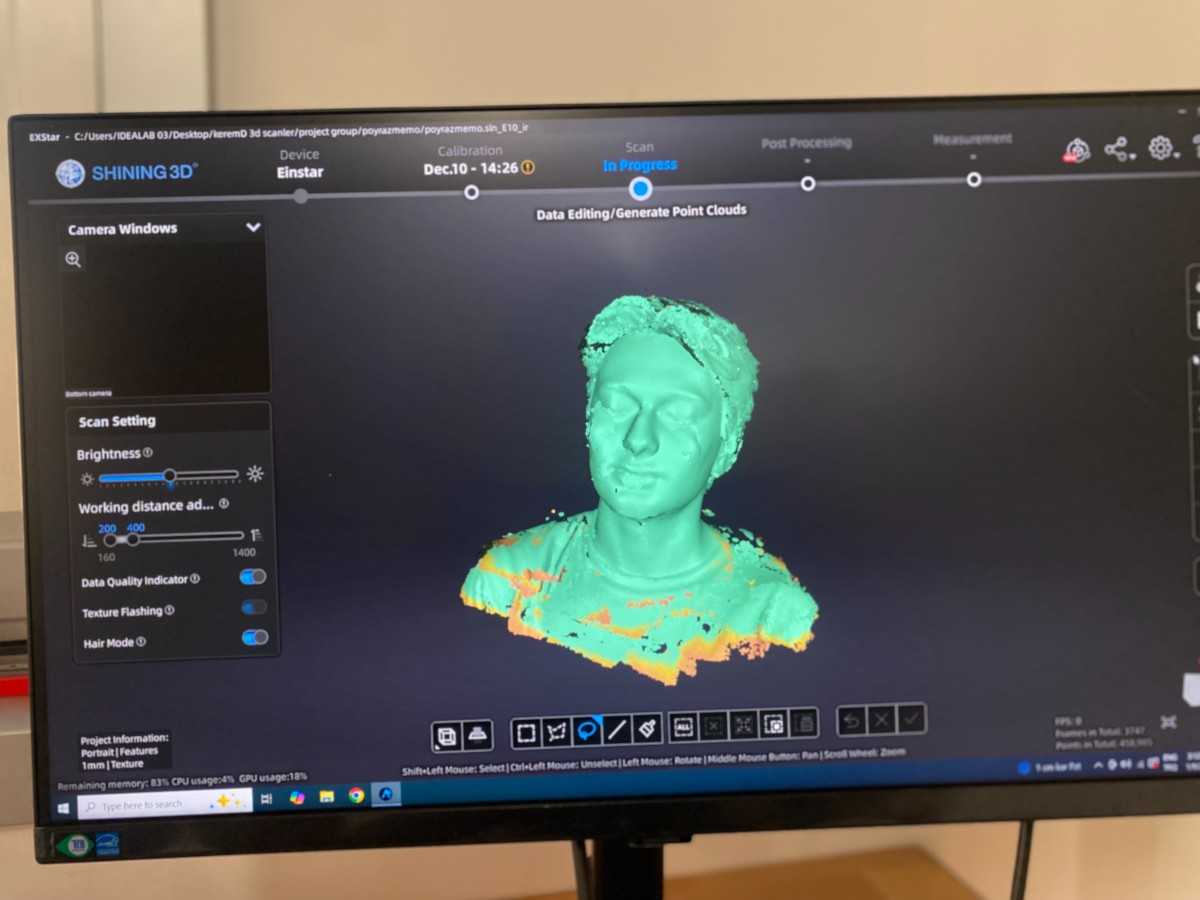
At this stage the model exists as a raw triangulated surface that represents the physical object.
4. Mesh Processing
The scan was converted into a watertight printable mesh using built-in processing tools:
- Noise removal
- Hole filling
- Surface smoothing
- Polygon remeshing
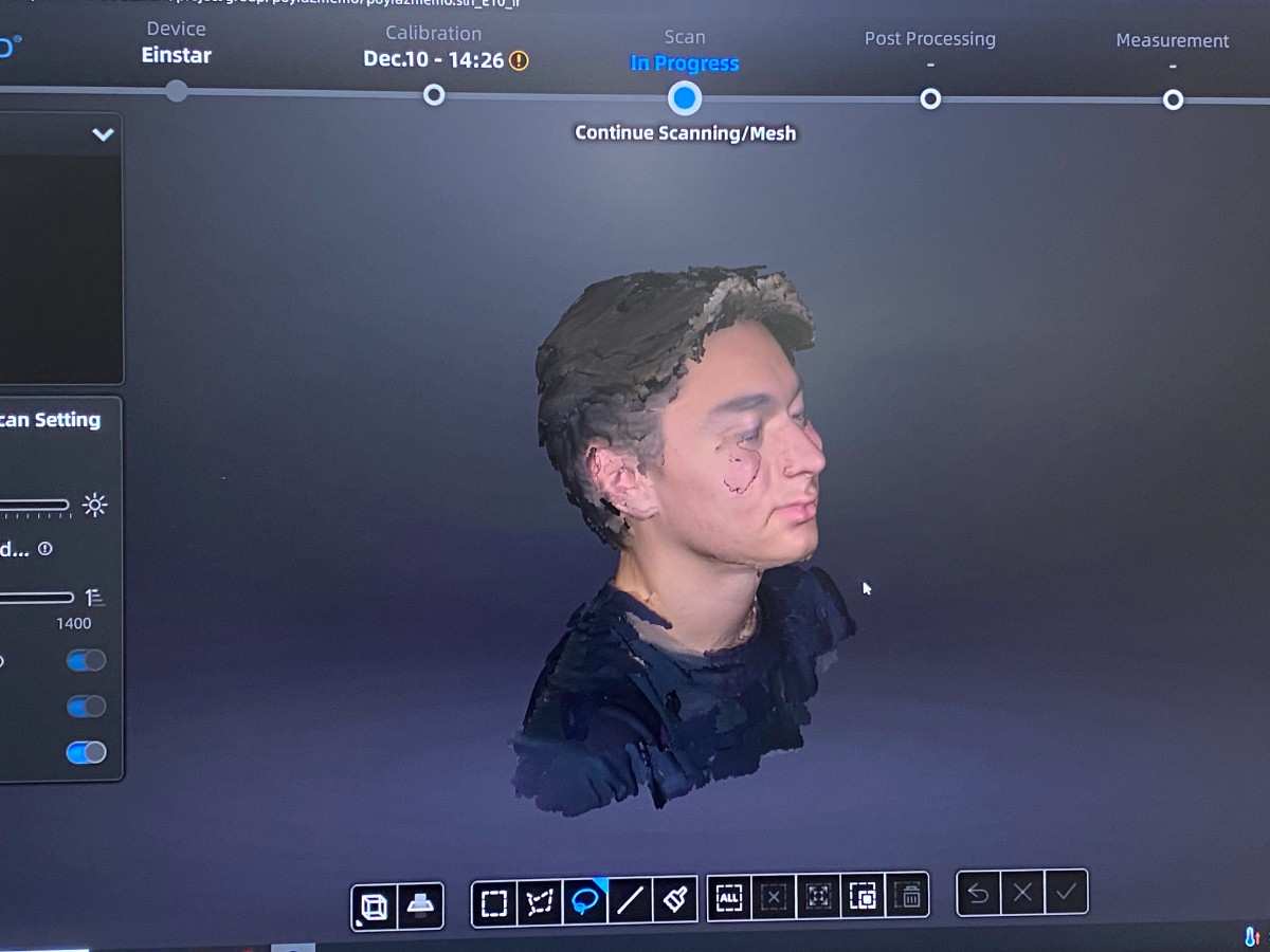
This transforms the raw scan into a solid digital model ready for fabrication.
5. Scaling for Printing
To better fit the printer volume and reduce material usage, I scaled the model by 15%.
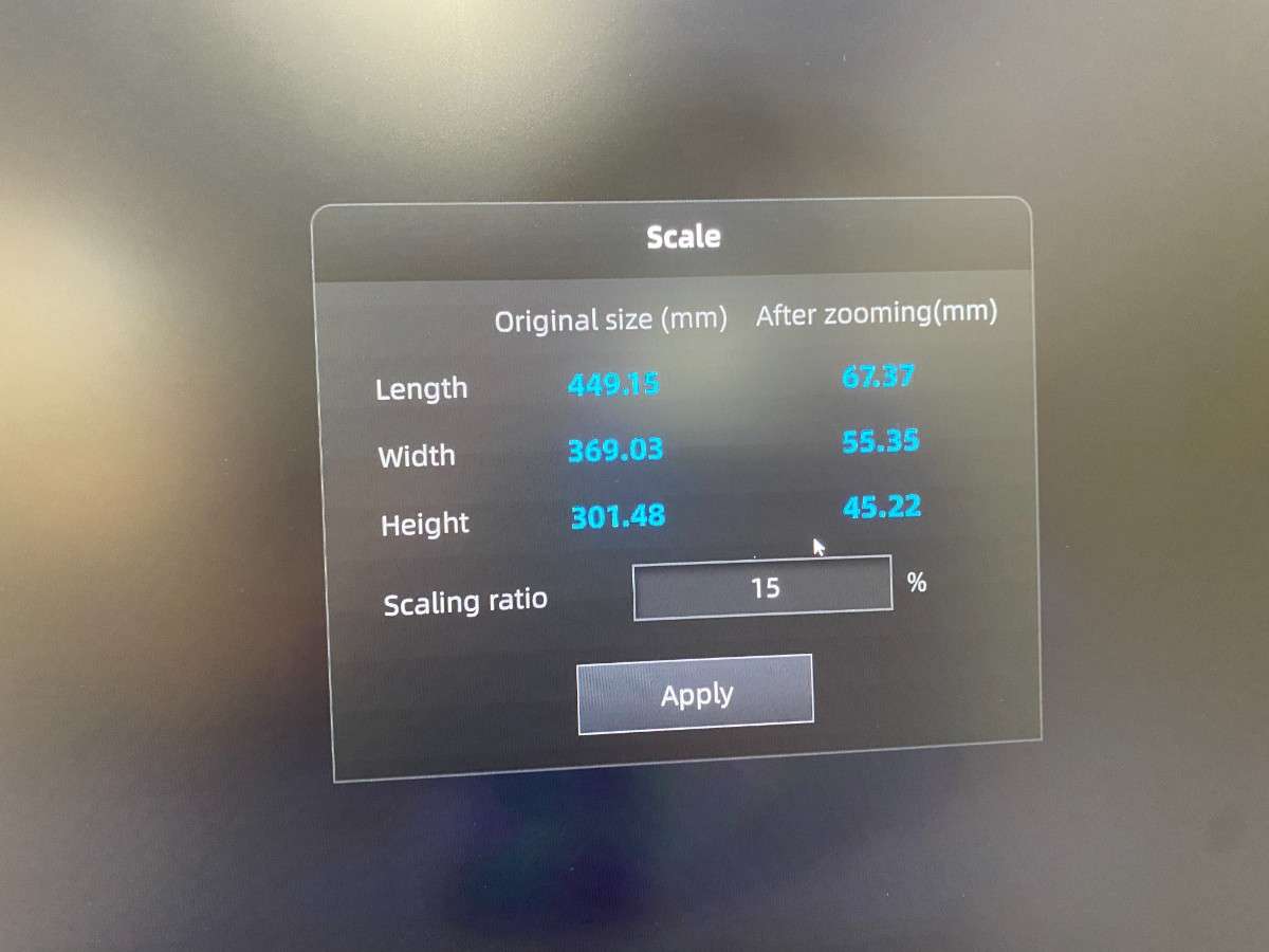
This shows how scanned geometry can be digitally modified before fabrication.
6. Preparing for 3D Printing
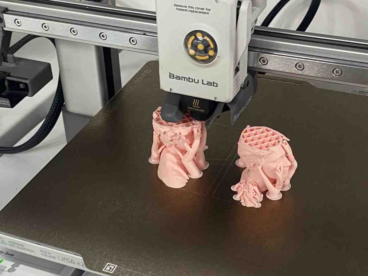
The processed STL was imported into Bambu Studio.
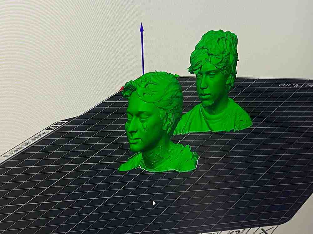
Supports were generated to handle overhangs and complex geometry.
At this point the scanned object has been fully converted from physical → digital → printable.
3D Printing
I gave the print to a Bambulab A1 printer with PLA filament.
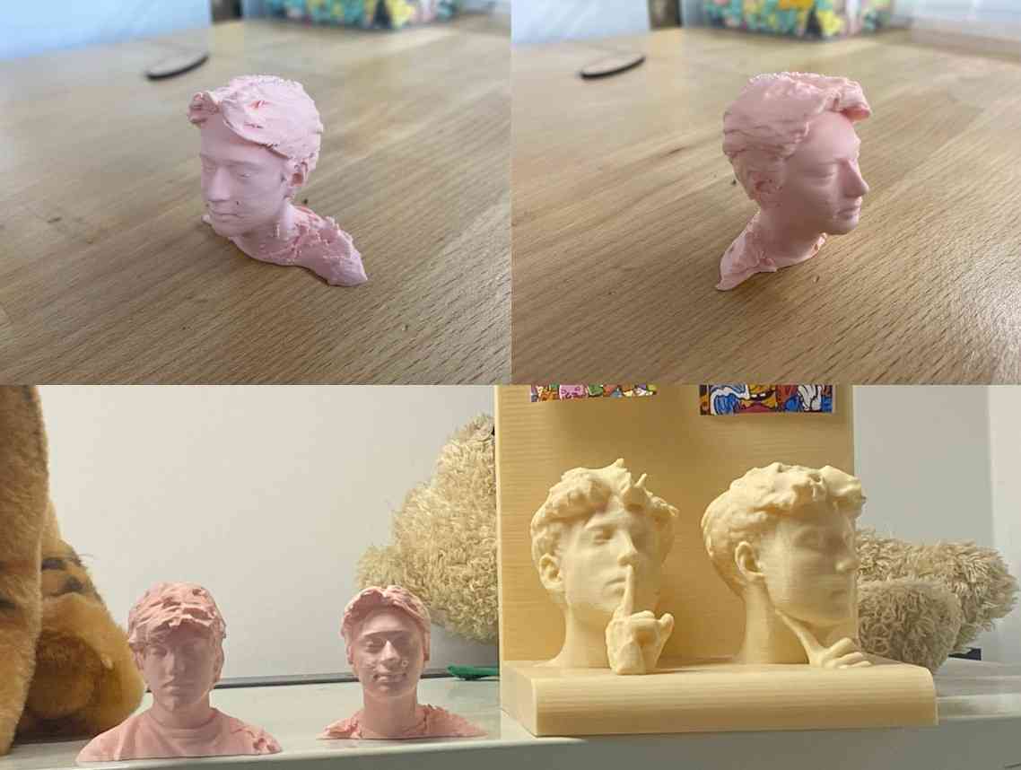
Here’s a hero shot of the final print of our 3D scan:
What 3D Scanning Enables
This workflow demonstrates that 3D scanning allows:
- Reverse-engineering real objects
- Capturing organic and irregular shapes
- Editing physical objects digitally
- Reproducing geometry through 3D printing
Unlike manual CAD, scanning captures complex free-form surfaces that would be extremely difficult to model by hand.
Reflection on 3D Scanning
Using the EinStar scanner taught me that:
- Scan quality depends heavily on coverage and angle
- Raw scans always require mesh cleanup
- Scaling and preparation are essential before printing
- 3D scanning bridges the physical and digital worlds
This demonstrates the complete scan → mesh → modify → fabricate workflow required for Fab Academy Week 5.
Reflection
What I Learned
About 3D Printing
- Additive manufacturing enables internal, inaccessible geometries
- Clearances are critical to avoid fused moving parts
- Support strategy strongly affects post-processing effort
About My Printer (Bambu Lab P1S)
- Excellent dimensional accuracy
- Reliable support generation
- Smooth PLA surface finish
- Minimal tuning required for complex prints
Design Takeaways
- Internal motion must be planned before slicing
- Printing-in-place requires tolerance awareness
- Visual testing (rotation, shaking) is essential to verify success
This assignment clearly demonstrated the unique strengths of additive manufacturing.
Designing an object that cannot be assembled or machined forced me to think differently about geometry, constraints, and fabrication logic.
The final result successfully proves that the design could only exist because of 3D printing, which directly meets the goals of this week.
Group Project
You can check our group project here