Fireplace Tool Holder
This week’s assignment was to design, mill, and assemble a large object using a CNC machine. For my project, I designed and fabricated a parametric fireplace tool holder for my home. The holder organizes fireplace tools and keeps them accessible next to the fireplace.
The project was designed parametrically in Fusion 360, exported to DXF, and machined using VCarve CAM toolpaths on a large format CNC router using 20 mm plywood and a 6 mm flat end mill.
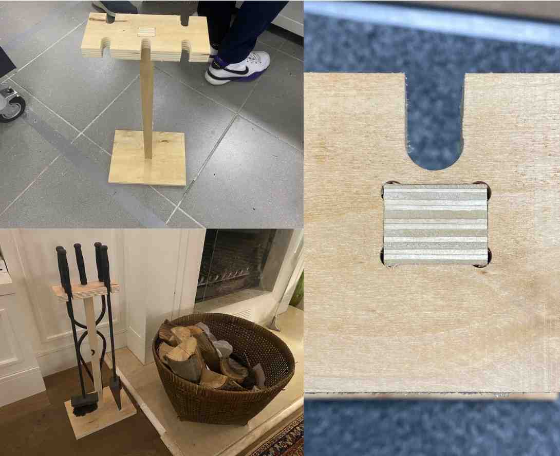
The final result is a three-part structure assembled using snap-fit joints, with inside dogbone fillets allowing the CNC tool to properly machine internal corners. The parts fit together perfectly with pure friction fit, requiring no glue or screws.
Final Result
The final product is a freestanding fireplace tool holder capable of holding four fireplace tools.
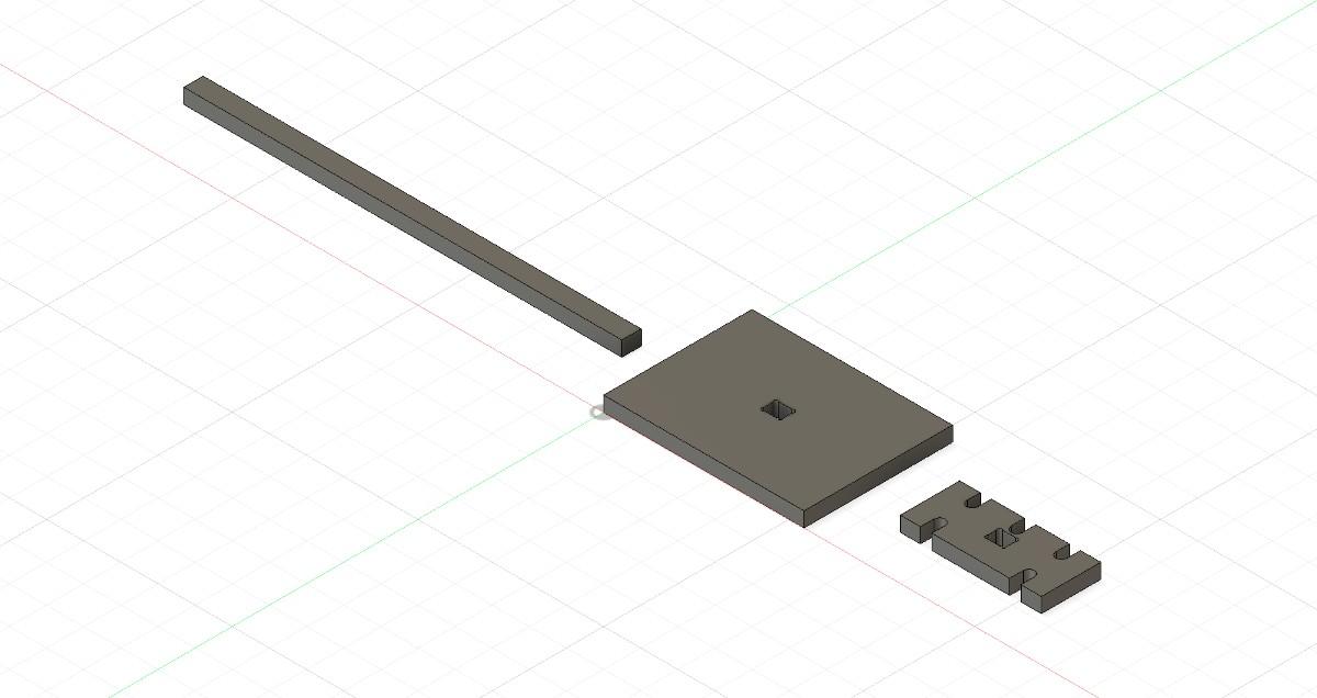
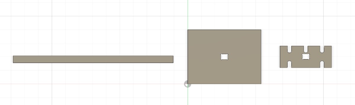
The structure consists of three main parts:
- Base plate — provides stability
- Vertical support stick — structural connector
- Top plate — holds the fireplace tools
The parts interlock using snap-fit joinery and do not require glue or fasteners.
Design Process
Parametric Design in Fusion 360
The entire structure was designed parametrically in Fusion 360. Parametric modeling allows the design to adapt automatically if key dimensions change.
Benefits of parametric design include:
- Easy adjustment of material thickness
- Automatic updates of slot sizes
- Adjustable structure height
- Adaptation for different tool sizes
3D Model
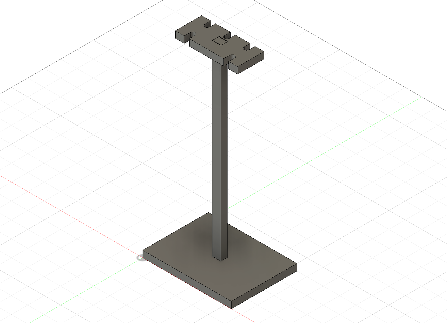
The 3D model includes the base, vertical support element, and top plate with holes for the tools.
Parameters
The model is controlled using Fusion 360 user parameters.
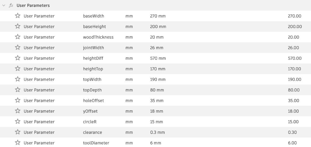
| Parameter | Description |
|---|---|
| baseWidth | Width of base plate |
| baseHeight | Height of base plate |
| woodThickness | Thickness of plywood |
| jointWidth | Width of snap-fit slots |
| heightDiff | Height of vertical support |
| heightTop | Thickness of top plate |
| topWidth | Width of top plate |
| topDepth | Depth of top plate |
| holeOffset | Spacing between tool holes |
| yOffset | Vertical offset for geometry |
| circleR | Radius of tool holes |
| clearance | Snap-fit tolerance |
| toolDiameter | CNC tool diameter |
Important Parameters
Material thickness:
woodThickness = 20 mm
Snap-fit tolerance:
clearance = 0.3 mm
Tool diameter:
toolDiameter = 6 mm
Using these parameters ensures the design automatically adapts to machining constraints.
Preparing the CNC Geometry
Converting 3D Model to 2D Layout
Once the design was complete, the components were converted into flat 2D geometry for CNC cutting.
This layout shows how the parts will be cut from the sheet material.
Top view of the 2D geometry:
Dogbone Fillets
CNC routers use cylindrical cutting tools, meaning they cannot cut perfectly sharp internal corners.
To allow rectangular joints to fit properly, I used inside dogbone fillets.
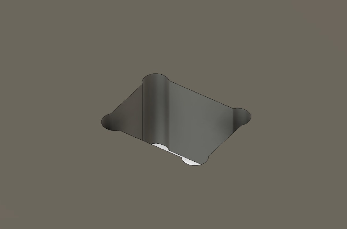
Dogbones remove extra material at the corner of joints so square tabs can fully insert.
The dogbone size corresponds to the tool size:
Tool diameter = 6 mm
Dogbone radius = 3 mm
Real Joint Result
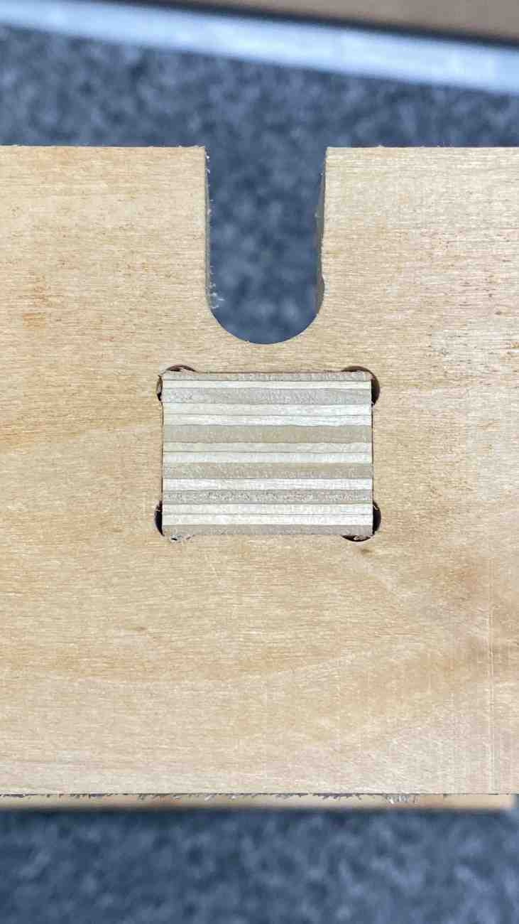
The dogbones ensured the parts fit together perfectly during assembly.
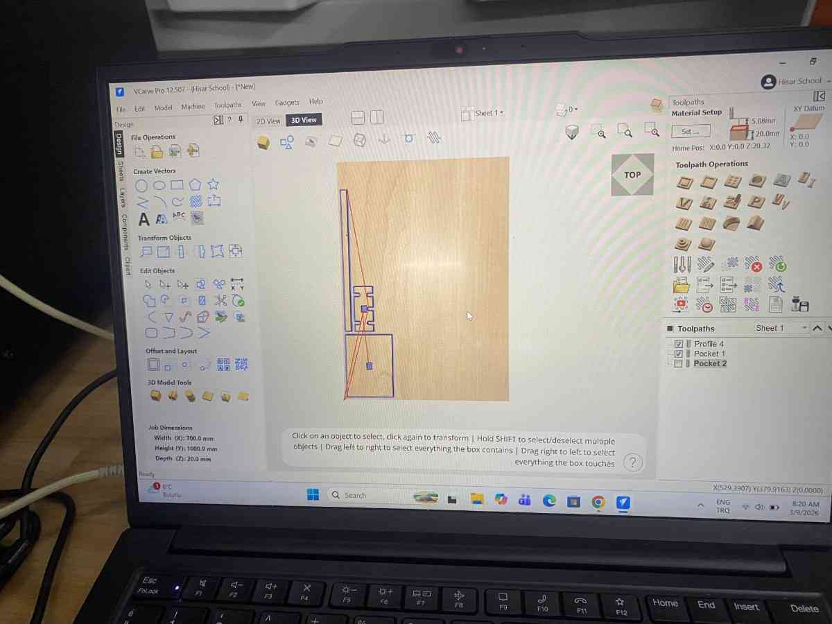
CAM Workflow in VCarve
After exporting the DXF file from Fusion 360, the geometry was imported into VCarve to generate the CNC toolpaths.
VCarve was used to:
- define the material size
- select the cutting tool
- generate profile toolpaths
- simulate the machining process
- export the final toolpaths for the CNC router
Job Setup
When creating a new job in VCarve, the material dimensions must be specified.
| Parameter | Value |
|---|---|
| Job Type | Single sided |
| XY Datum Position | Bottom left |
| Z Zero Position | Material surface |
| Material Thickness | 20 mm |
| Safe Z Height | 20 mm |
Setting the Z zero at the material surface ensures accurate depth control.
Tool Definition
The tool used for machining was a 6 mm flat end mill.
| Parameter | Value |
|---|---|
| Tool Type | Flat End Mill |
| Diameter | 6 mm |
| Pass Depth | 5 mm |
| Stepover | 40 % |
| Spindle Speed | 18,000 RPM |
| Feed Rate | 3000 mm/min |
| Plunge Rate | 1000 mm/min |
Using multiple passes is necessary when cutting thick plywood to reduce tool load.
With a 5 mm pass depth, the 20 mm sheet requires 4 passes.
Profile Toolpaths
The parts were cut using Profile Toolpaths.
Two types of profile cuts were used:
| Geometry | Toolpath |
|---|---|
| Slots and internal cuts | Inside profile |
| Outer part outlines | Outside profile |
This ensures the final parts maintain the correct dimensions.
Cut Depth
The cut depth was set slightly deeper than the material thickness to ensure full separation of the parts.
| Parameter | Value |
|---|---|
| Material Thickness | 20 mm |
| Cut Depth | 20.5 mm |
The additional 0.5 mm ensures the tool cuts completely through the board.
Ramping
To reduce tool stress when entering the material, ramp entry was enabled.
| Parameter | Value |
|---|---|
| Ramp Type | Smooth ramp |
| Ramp Distance | 15 mm |
This allows the tool to gradually enter the material instead of plunging directly.
Tabs
Tabs are often used to keep parts attached to the sheet during cutting.
For this project, tabs were not necessary because:
- the parts were large
- the geometry supported itself
- the material remained stable during machining
Toolpath Simulation
Before machining, the toolpaths were simulated in VCarve.
Simulation allows verification of:
- correct cut depth
- toolpath direction
- material removal
- potential errors
The simulation confirmed that all parts would cut correctly and separate from the material.
Exporting the Toolpaths
After verifying the toolpaths, they were exported as a machine file compatible with the CNC router.
The CNC machine then followed these toolpaths to cut the parts from the plywood sheet.
Machine Setup
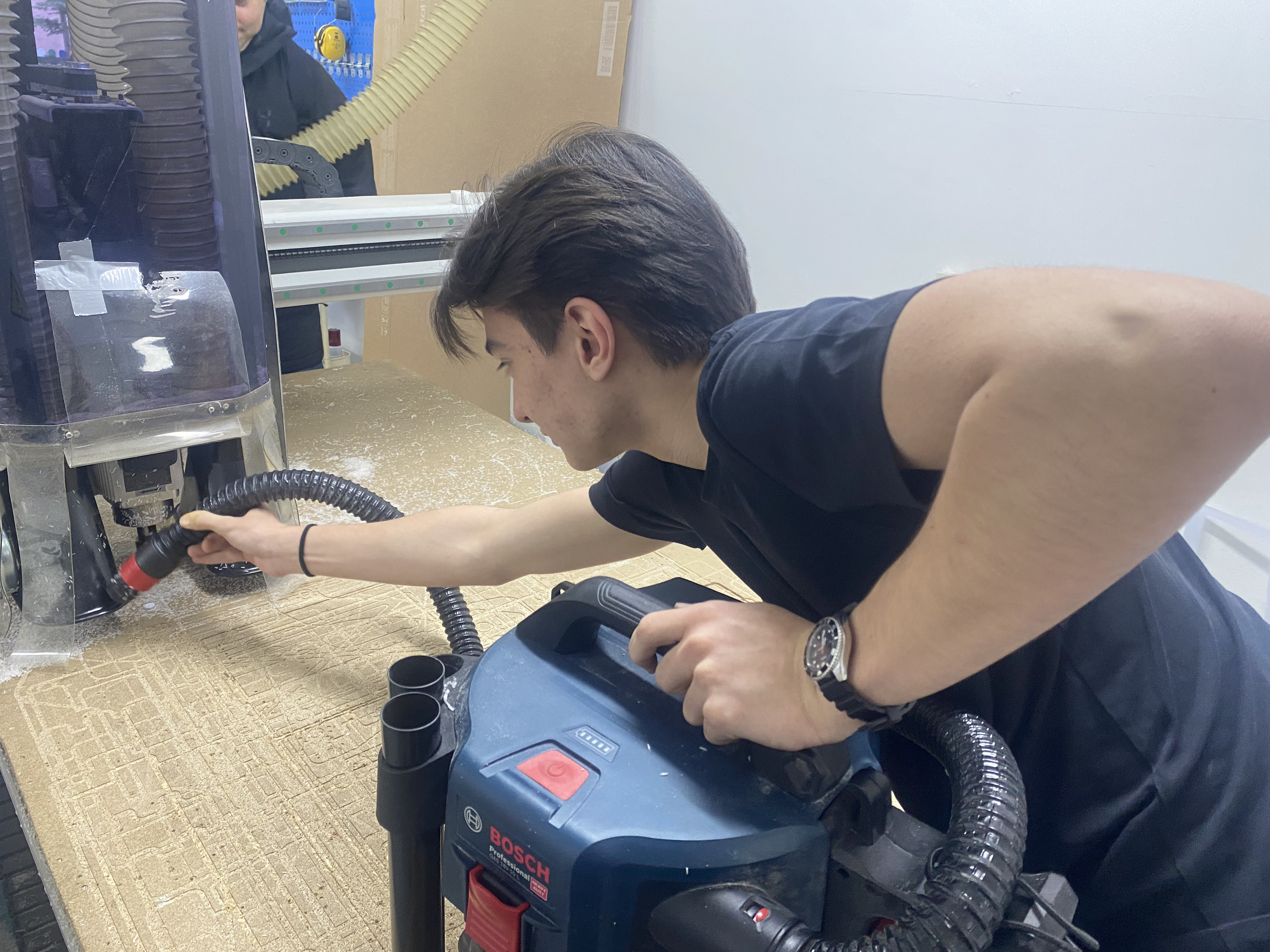
The project was fabricated using a large format locally produced Turkish CNC router.
Before starting the machining process the machine must be prepared properly.
Cleaning the Machine
Before running the CNC machine, I cleaned the machine bed to remove debris from previous use.
Cleaning ensures:
- accurate positioning
- safe operation
- better fixturing
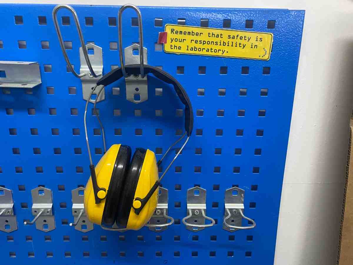
Safety
Operating large CNC machines requires strict safety precautions.
Important safety rules include:
- wear ear protection
- keep distance from the cutting tool
- never leave the machine unattended
- ensure material is securely fixed
- double-check toolpaths before cutting
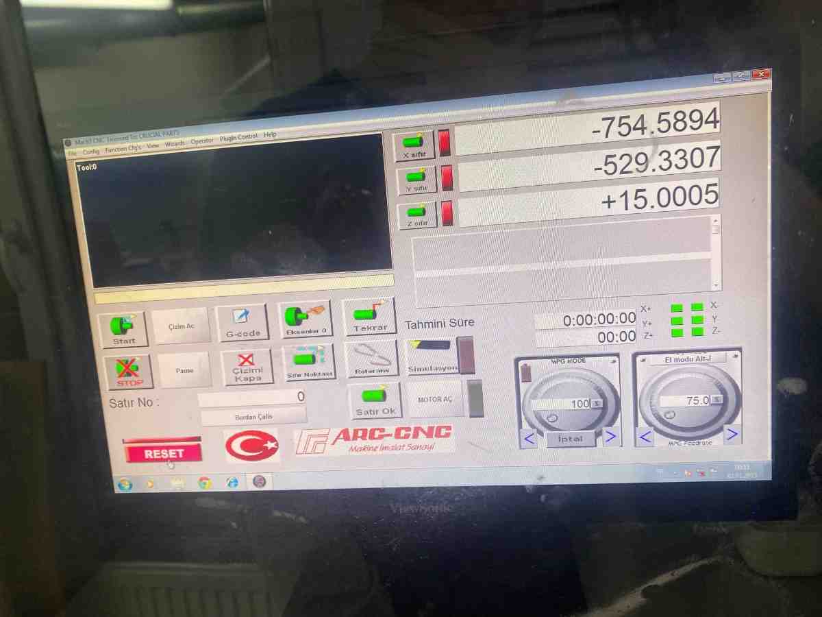
Setting Machine Coordinates
Before starting the machining process, the machine origin must be defined.
This includes setting:
- X origin
- Y origin
- Z origin
Correct origin setup ensures the CNC machine follows the intended toolpaths.
CNC Machining Process
After the setup was completed, the machining process began.
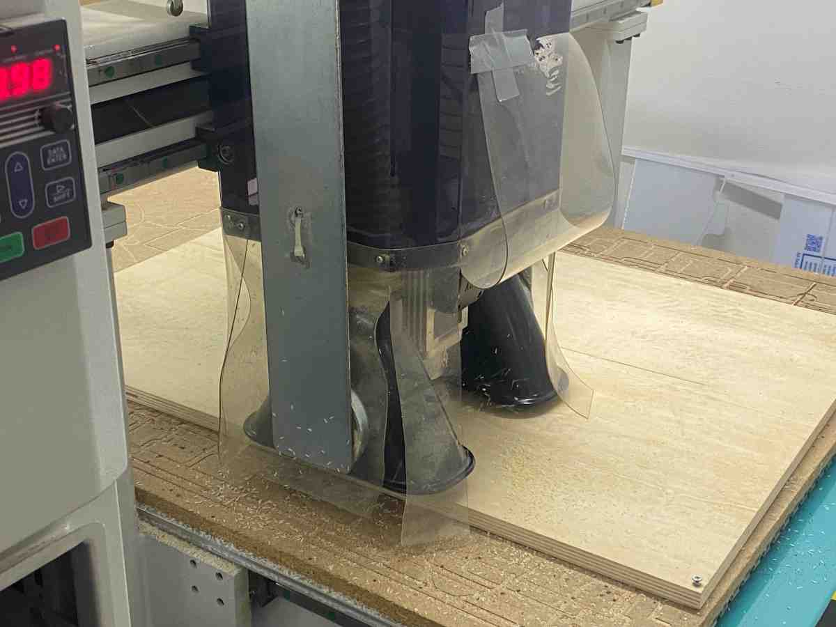
The CNC machine follows the toolpaths generated in VCarve and removes material layer by layer.
Machining Video
Additional stage of the machining process:
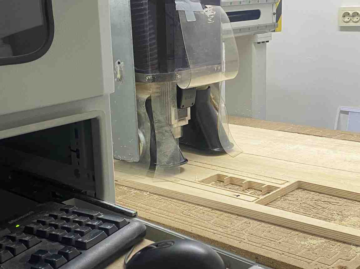
The 6 mm flat end mill cut all components from the 20 mm plywood sheet.
Assembly
After machining, the parts were removed and assembled.
The structure consists of three parts:
- Base plate
- Vertical structural stick
- Top plate holding the tools
The vertical stick connects the base plate and top plate.
All joints were designed as snap-fit joints, meaning:
- no screws
- no glue
- pure friction fit
Thanks to the correct clearance parameter, the parts fit perfectly on the first attempt.
The structure is rigid and stable.
Final Product
The finished fireplace tool holder can hold four fireplace tools.
The circular holes in the top plate keep the tools upright, while the base plate stabilizes the structure.
The final design is:
- functional
- minimal
- structurally stable
Because the model is parametric, it can easily be modified to:
- hold more tools
- change the height
- adapt to different material thicknesses
What I Learned
This assignment taught me several important aspects of large format CNC fabrication.
Parametric Design
Parametric modeling allows rapid changes to the design without rebuilding the geometry.
Changing one parameter automatically updates the entire structure.
Dogbone Joinery
Dogbone fillets are necessary when using CNC routers because round tools cannot produce sharp internal corners.
Proper dogbone design ensures joints fit correctly.
CAM Workflow
The workflow from Fusion → DXF → VCarve → CNC machine is a standard digital fabrication pipeline.
Understanding toolpaths and machining operations is critical for successful results.
CNC Machine Operation
Operating a CNC machine requires:
- proper machine setup
- correct coordinate definition
- safe operation practices
Reflection
This project successfully demonstrates the complete CNC fabrication workflow from design to assembly.
The final product achieved:
- precise machining
- perfect snap-fit joints
- strong structural stability
The project also produced a useful object for my home, making the assignment both technical and practical.
Group Project
You can check our group project here