This week focuses on sensing physical input using electronic input devices and a microcontroller board.
The goal is to understand how physical interaction is translated into digital signals, how those signals are read by a microcontroller, and how they can be observed, processed, and debugged.
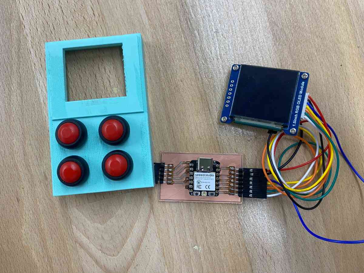
For this assignment, I used the custom PCB I designed for my final project and interfaced four push buttons as digital input devices.
Learning Outcomes
- Demonstrate workflows used in sensing physical input with input device(s) and a microcontroller
- Probe and interpret digital signals generated by input devices
- Implement firmware to reliably read and process input signals
1. Introduction
Input devices allow physical phenomena, such as pressing a button to be converted into electrical signals that a microcontroller can interpret.
In this assignment, I measured discrete user input using four push buttons connected directly to my custom ESP32-C3 PCB.
Each button generates a digital signal (HIGH/LOW), which I read using internal pull-up resistors and processed in firmware.
2. Input Device Selection
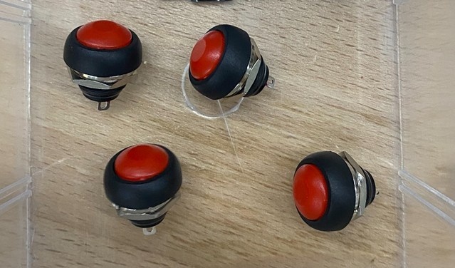
Push Buttons (Digital Input)
Each push button functions as a momentary switch:
- Pressed → circuit closes → GPIO pulled LOW
- Released → circuit open → GPIO pulled HIGH (via pull-up)
Why Buttons?
- Simple, reliable digital input
- Easy to probe and debug
- Ideal for demonstrating digital signal behavior
- Commonly used in embedded systems
3. Custom PCB
All input devices are connected directly to a custom PCB.
Board Used
- Final Project PCB
- Designed and documented in Week 6 — Electronics Design
- Microcontroller: ESP32-C3 Super Mini
➡️ Board design details, schematic, and PCB layout are fully documented in Week 6.
Button Wiring (On PCB)
Each button is wired as follows:
- One side → GPIO pin
- Other side → GND
- Internal pull-up enabled in firmware
GPIO Mapping
| Button | GPIO | Label |
|---|---|---|
| BTN1 | GPIO2 | Option A |
| BTN2 | GPIO6 | Option B |
| BTN3 | GPIO4 | Option C |
| BTN4 | GPIO3 | Option D |
This configuration ensures a clean digital signal without external resistors.
4. Probing the Input Device
What Does “Probe an Input Device” Mean?
Probing means observing the electrical signal produced by a sensor or input device using test equipment.
How I Probed the Buttons
I probed the buttons using:
- Multimeter (voltage & continuity mode)
- Serial monitor output (logical probing)
Observations
| Button State | GPIO Voltage | Logic Level |
|---|---|---|
| Released | ~3.3 V | HIGH |
| Pressed | ~0 V | LOW |
This confirms:
- Internal pull-ups are working correctly
- Buttons generate clean digital transitions
- No floating inputs are present
5. Firmware & Programming
Programming Environment
- Arduino IDE
- Board core: ESP32-C3
- Communication: USB Serial (UART)
Firmware Strategy
Key concepts implemented:
- Internal pull-up resistors
- Digital input reading
- Edge detection
- Software debouncing
- Serial feedback
Code Overview
GPIO Assignment
int buttons[] = {2, 6, 4, 3};
const char* labels[] = {"Option A", "Option B", "Option C", "Option D"};
int lastState[4];
- Buttons stored in an array for scalable logic
- Labels used for readable serial output
- lastState[] tracks previous button states
Setup Phase
void setup() {
  Serial.begin(115200);
  delay(500);

  for (int i = 0; i < 4; i++) {
    pinMode(buttons[i], INPUT_PULLUP);
    lastState[i] = HIGH;
  }
}
What this does:
- Enables internal pull-ups
- Ensures default HIGH state
- Prevents floating inputs
- Initializes serial communication
Loop Logic (Edge Detection + Debounce)
int current = digitalRead(buttons[i]);

if (current == LOW && lastState[i] == HIGH) {
  delay(10);
  if (digitalRead(buttons[i]) == LOW) {
    Serial.print(labels[i]);
    Serial.println(" pressed!");
    lastState[i] = LOW;
  }
}
Why this matters:
- Detects new presses only
- Prevents repeated triggers
- Handles mechanical bouncing
- Ensures stable readings
6. Demo & Results
The video below shows the demo:
Problems & Fixes
Issue 1 — Button Bounce
Symptom:
- Single press registered multiple times.
Fix:
- Added 10 ms debounce delay
- Implemented edge detection
Issue 2 — Floating Inputs (Early Test)
Symptom:
- Random button presses detected.
Fix:
- Enabled INPUT_PULLUP
- Verified ground continuity
- Probed voltage levels
6. Group Project
You can check our group project here
7. Files
- Download Source Code
- PCB Design: See Week 6 — Electronics Design
8. Reflection
This assignment strengthened my understanding of human–machine interaction at the electrical level. Even a simple button requires careful consideration of signal stability, hardware design, and firmware logic.
By using my own PCB, probing real signals, and writing debounced firmware, I demonstrated a complete and correct input-device workflow, fully aligned with Fab Academy expectations.