Learning Objectives
- Demonstrate workflows used in controlling an output device(s) with MCU board you have designed.
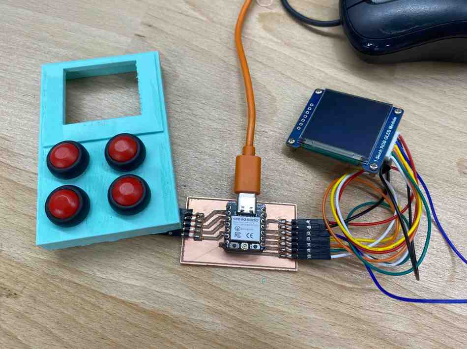
Hero Shot
1. Introduction
For Week 10, my main goal was to control an output device using a microcontroller board that I had designed myself. Instead of making the servo motor the center of the assignment, I decided to focus on the 1.5 inch RGB OLED screen used in my final project. This made more sense because the screen is one of the most important parts of the final device and required much deeper integration with my custom PCB.
The board I used is the custom ESP32-C3 final project PCB that I designed earlier in Week 6. This board includes the ESP32-C3, four push buttons, and a custom 7-pin connector for the OLED screen. Because this is the real PCB for my final project, Week 10 became more than a simple weekly exercise: it became a way to validate that an important part of my final system already works in real hardware.
As a secondary output-device test, I also experimented with a continuous rotation servo motor, but that was only a side test. The main output device for this week was the OLED display.
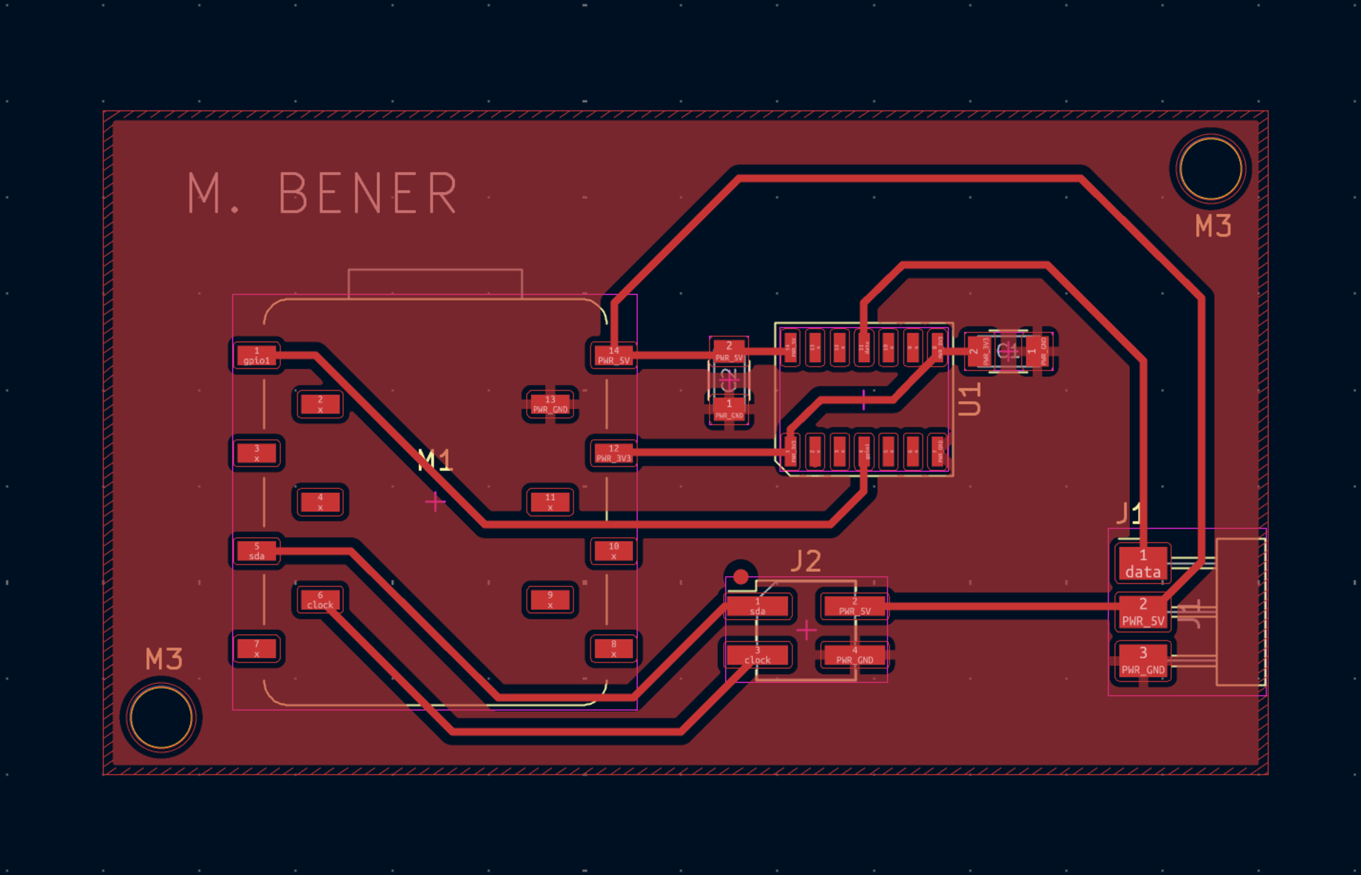
2. Board Design and OLED Integration
The OLED module I used is a 1.5 inch RGB OLED screen connected with a 7-pin SPI interface. In Week 6, I had already designed the PCB specifically for this display, so Week 10 was the moment to bring that design to life.
The OLED wiring on my board is:
| OLED Pin | ESP32-C3 Pin | Function |
|---|---|---|
| VCC | 3V3 | Power |
| GND | GND | Ground |
| SCK | D9 | SPI Clock |
| MOSI | D10 | SPI Data |
| RST | D6 | Reset |
| DC | D8 | Data / Command |
| CS | D7 | Chip Select |
All of these pins operate in the 3.3 V domain, so no level shifting was required. That made the display a very natural fit for my board and for my final project.
One important challenge during the board design stage was the OLED connector itself. The standard Fab library did not include the PH2.0 7-pin footprint that I needed, so I created a custom symbol and footprint for it. This was an important step because it allowed me to build the board around the exact screen I wanted to use instead of changing the design to fit the available library parts.
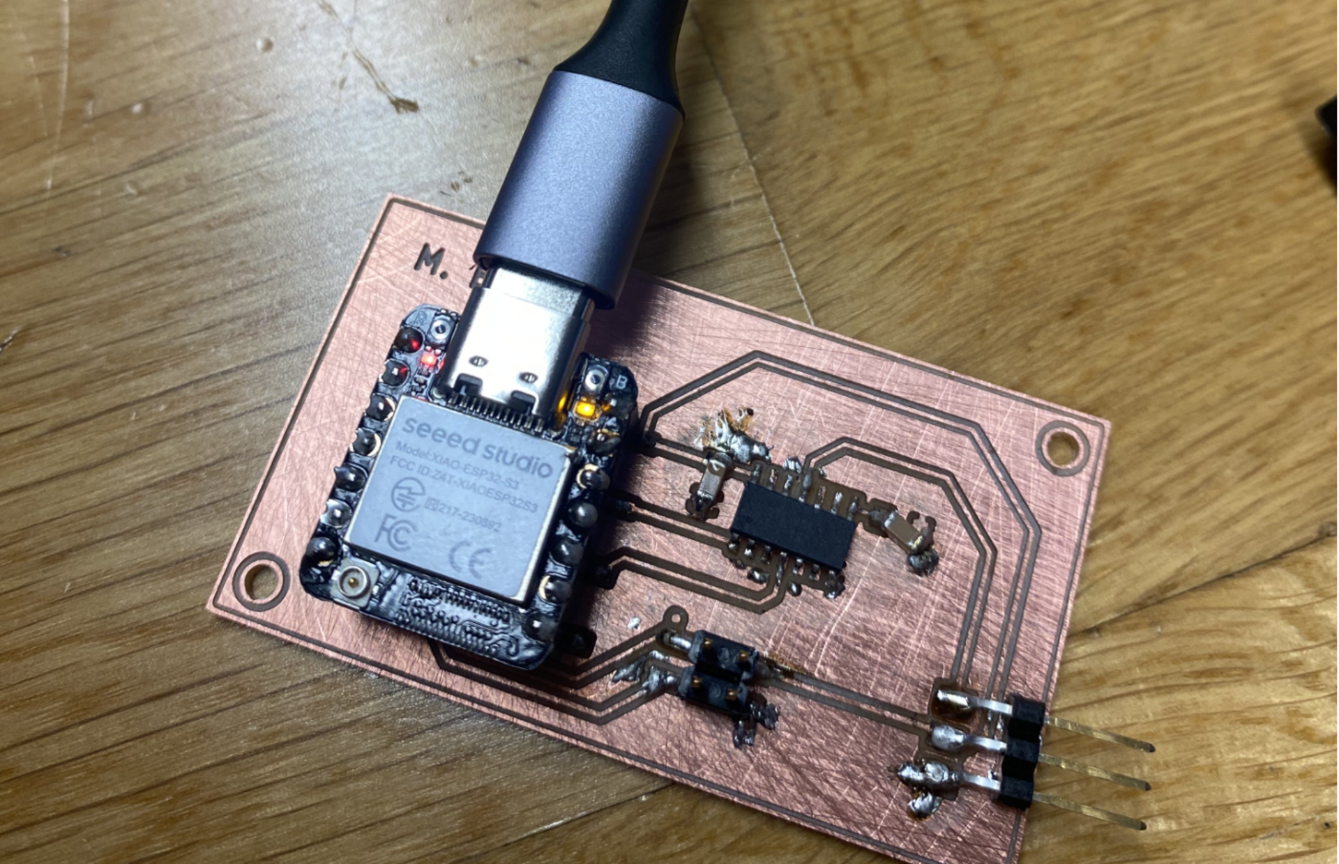
The board was then fabricated using the Roland SRM-20 in our lab. After milling the traces and outline, I soldered the components by hand and connected the OLED module for testing.
3. Programming and Testing the OLED
After assembling the board, I tested whether the OLED could be successfully controlled by the ESP32-C3. This step was important because it verified much more than just the display itself. It confirmed that the custom PCB traces, the connector design, the soldering quality, and the pin mapping were all correct.
To test the screen, I initialized the OLED through SPI and displayed visual output on it. This showed that the complete signal path worked correctly:
ESP32-C3 → PCB traces → custom 7-pin OLED connector → OLED display
This was especially meaningful because the display is not just a demonstration component. It is the main visual interface of my final project, where I plan to show questions, options, and user feedback directly on the screen.
I used the following test code:
#include <Adafruit_GFX.h>
#include <Adafruit_SSD1351.h>

#define SCREEN_WIDTH 128
#define SCREEN_HEIGHT 128

// OLED pins
#define OLED_CS   8
#define OLED_DC   20
#define OLED_MOSI 10
#define OLED_CLK  9
#define OLED_RST  21

Adafruit_SSD1351 display(
  SCREEN_WIDTH,
  SCREEN_HEIGHT,
  OLED_CS,
  OLED_DC,
  OLED_MOSI,
  OLED_CLK,
  OLED_RST
);

// Working button GPIOs on your PCB
int buttons[] = {2, 6, 4, 3};
const char* labels[] = {"Option A", "Option B", "Option C", "Option D"};
int lastState[4];

void showLabel(const char* text, uint16_t color) {
  display.fillScreen(0x0000);
  display.setTextColor(color);
  display.setTextSize(2);
  display.setCursor(10, 20);
  display.println("Pressed:");
  display.setCursor(10, 60);
  display.println(text);
}

void setup() {
  display.begin();
  display.fillScreen(0x0000);
  display.setTextColor(0xFFFF);
  display.setTextSize(2);
  display.setCursor(10, 20);
  display.println("Ready");
  display.setTextSize(1);
  display.setCursor(10, 60);
  display.println("Press a button");

  for (int i = 0; i < 4; i++) {
    pinMode(buttons[i], INPUT_PULLUP);
    lastState[i] = HIGH;
  }
}

void loop() {
  for (int i = 0; i < 4; i++) {
    int current = digitalRead(buttons[i]);

    if (current == LOW && lastState[i] == HIGH) {
      delay(10);
      if (digitalRead(buttons[i]) == LOW) {
        uint16_t color = 0xFFFF;

        if (i == 0) color = 0xF800; // red
        if (i == 1) color = 0x07E0; // green
        if (i == 2) color = 0x001F; // blue
        if (i == 3) color = 0xFFE0; // yellow

        showLabel(labels[i], color);
        lastState[i] = LOW;
      }
    }

    if (current == HIGH && lastState[i] == LOW) {
      lastState[i] = HIGH;
    }
  }
}
Working Demo
This successful test showed that the OLED worked reliably on the custom board and confirmed that the display system of my final project is already functional.
4. Servo as a Secondary Output Test
Besides the OLED display, I also tested a continuous rotation servo motor as a secondary output-device experiment during Week 10. This was not the central focus of the week, since the OLED screen is much more important for my final project, but it was still a useful supporting test because it allowed me to work with another type of output device: a motor-based actuator controlled through PWM.
Compared to the OLED, the servo introduced a different set of engineering constraints. The screen was already well matched to my board because it operates fully in the 3.3 V domain and communicates over SPI, which I had already planned for in my final project PCB. The servo, however, required more attention to power consumption, voltage compatibility, and signal conditioning, so it became a good side experiment for understanding how output devices can differ in their electrical and control requirements.
Before connecting the servo, I first considered its approximate electrical characteristics:
- Voltage: 5 V
- Idle current: ~10–15 mA
- No-load rotation current: ~100–150 mA
- Stall current: up to ~700–800 mA
These values showed that the servo could not be powered safely from the ESP32-C3 board’s 3.3 V regulator. The board regulator is intended for low-power logic electronics, not a motor load with large current spikes. The stall current in particular made it clear that the servo needed a dedicated 5 V supply. This also meant that the PWM control signal from the ESP32-C3 had to be considered separately, since the microcontroller outputs 3.3 V logic while the servo is designed around a 5 V operating environment. For this reason, I used a 3.3 V → 5 V level shifter in the signal path.
To correctly drive the continuous rotation servo, I also reviewed its expected control method. Like standard hobby servos, it uses a 50 Hz PWM signal, but instead of controlling angular position, the pulse width determines the direction and speed of rotation. In my setup:
- around 1500 µs corresponds to stop
- around 2000 µs corresponds to full-speed rotation in one direction
This made it a useful example of a PWM-controlled electromechanical output device.
After confirming that my ESP32-C3 board powered on correctly, I connected the servo through the 3×1 header I had designed earlier on the board.
Design of board:
First, I verified that the board powered normally:
Then I connected:
- 5 V
- GND
- level-shifted PWM pin
through the output header on the PCB:
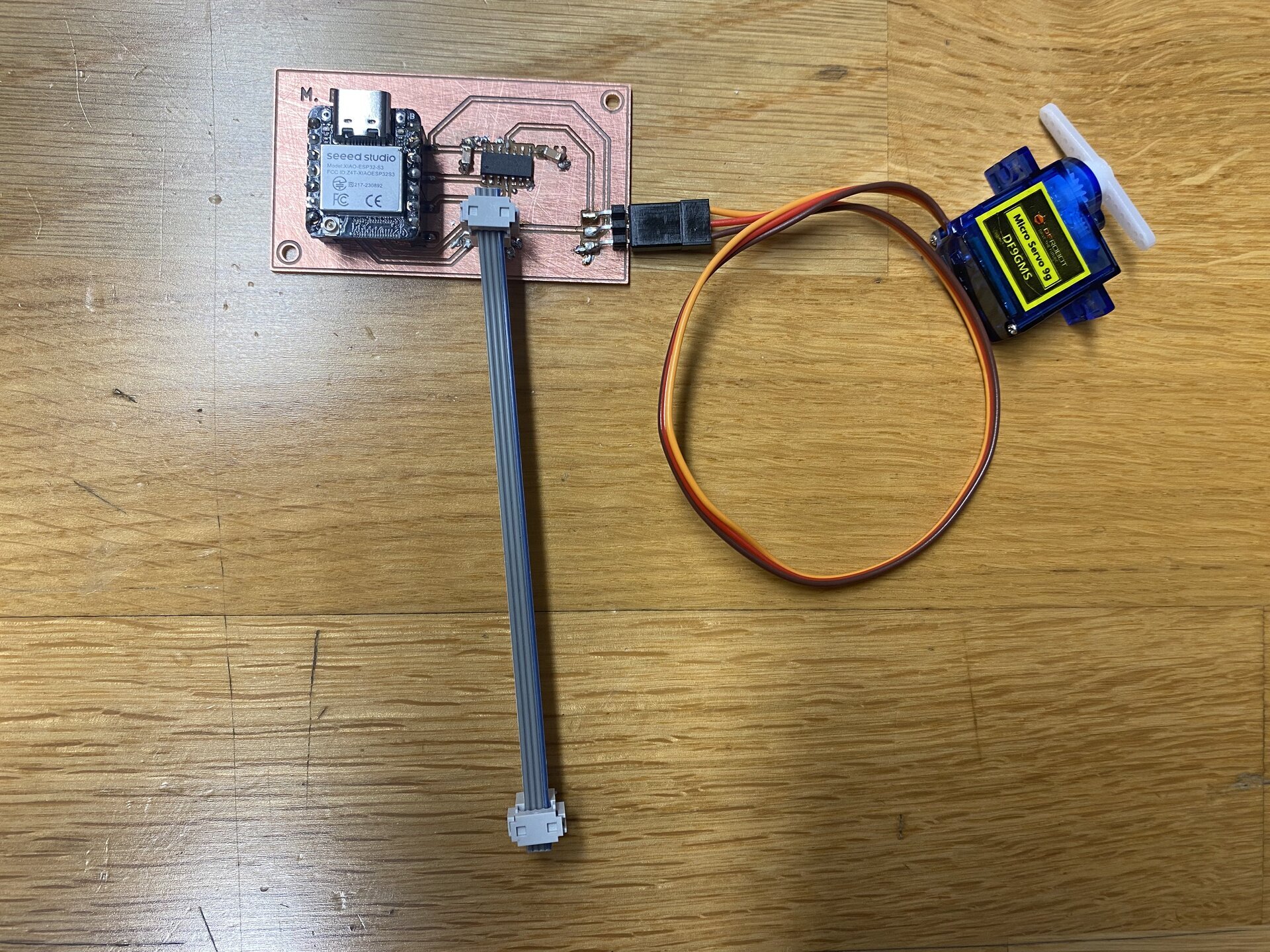
This setup confirmed that the board could not only drive the OLED screen for my final project, but could also interface with an external motor-based output device when the correct support circuitry was added.
I then programmed the servo using the following code:
#include <ESP32Servo.h>

Servo s;

void setup() {
  s.setPeriodHertz(50);
  s.attach(8, 500, 2500);
}

void loop() {
  s.writeMicroseconds(2000);
  delay(3000);
  s.writeMicroseconds(1500);
  while (true);
}
In this program:
setPeriodHertz(50)sets the standard servo refresh rateattach(8, 500, 2500)attaches the servo to pin 8 and defines the pulse-width rangewriteMicroseconds(2000)drives the servo at high speedwriteMicroseconds(1500)stops the servo
This confirmed the intended signal chain:
ESP32 3.3 V PWM → level shifter → servo input (5 V logic)
To program the OLED, I used the Adafruit_GFX and Adafruit_SSD1351 libraries because they provide a reliable and simple way to control SSD1351-based color OLED displays over SPI. Adafruit_SSD1351 handles the low-level communication and initialization sequence required by the display controller, while Adafruit_GFX provides easy text and graphics functions such as setting the cursor position, text size, and text color. In the code, display.begin() initializes the OLED and prepares it to receive commands and pixel data. I also configured the four push buttons as INPUT_PULLUP, which means each button normally reads HIGH and changes to LOW when pressed. The program continuously checks for this falling-edge transition from HIGH to LOW, and when it detects a valid press, it calls showLabel() to clear the screen and display the label of the selected option. I assigned a different color to each button so that the OLED response would be visually clearer and so I could confirm that each input was being detected correctly during testing.
Working Demo
The servo test successfully demonstrated that the board could control a PWM-based actuator, not just a screen. Even though this was only a secondary experiment, it was still valuable because it showed a different kind of output control workflow: one based on motion instead of visual feedback.
During this test, I also encountered a few physical debugging issues. One problem was a short between 5 V and a copper island, which I fixed by removing excess solder. Another issue was that some NC pins were shorting to GND, and I solved that using flux and solder wick. These were relatively small issues, but they reinforced an important lesson: even when the code and logic are correct, output-device testing can still fail because of small soldering defects or assembly mistakes on the physical board.
Overall, the servo was a useful secondary output-device test because it helped me explore power-aware design, PWM motor control, and level shifting on a custom microcontroller board. However, it remained a side experiment rather than the main achievement of Week 10. The OLED display is still the most important output device in this assignment because it is directly integrated into my final project board and represents the real user interface of the final system.
5. Problems, Fixes, and What I Learned
During assembly and testing, I encountered a few hardware problems that required debugging.
One issue was a short between 5V and a copper island, which I fixed by removing excess solder. Another issue was that some NC pins were shorting to GND, and I solved that using flux and solder wick. These problems reminded me that even when the schematic and code are correct, small soldering mistakes can still prevent a board from working properly.
This week taught me several things:
- how to drive a real SPI display from a custom ESP32-C3 board,
- how to validate a board designed earlier by testing it in real hardware,
- how useful custom footprints are when standard libraries are not enough,
- how output-device selection depends on voltage domain and system integration,
- and how debugging includes both software and physical electronics work.
Most importantly, this week showed me that weekly assignments do not have to be isolated exercises. By using the OLED screen from my final project board as the main output device, I turned the assignment into meaningful progress toward the final project itself.
6. Group Project
You can check our group project here
7. Files
- Download the files
- PCB Design: See Week 6 — Electronics Design