For this week, I used the custom PCB I had already developed in earlier weeks. The board includes an ESP32-C3, four push buttons, and an antenna for wireless communication. My goal was to turn this board into a wireless input node: when a local push button is pressed, the ESP32 reads the input and sends the button press data over Wi-Fi to a web application running on my laptop.
This project combines:
- a local input device: four push buttons on my PCB
- a wireless communication node: ESP32-C3
- a network address: Wi-Fi connection and server URL
- a remote output interface: a browser-based web app on my laptop
Final Result
My final system works as follows:
- The ESP32-C3 connects to my local Wi-Fi network.
- The ESP32 continuously monitors the four push buttons on my custom PCB.
- When a button is pressed, the ESP32 sends an HTTP POST request containing the button label and GPIO number.
- A Flask server running on my laptop receives the data.
- A browser-based web app updates and shows the latest message and message history.
This allowed me to demonstrate a fully working wireless node with local input and remote output.
System Architecture
The overall system is shown below:
[Push Buttons on PCB]
        ↓
 [ESP32-C3 on custom PCB]
        ↓   Wi-Fi / HTTP POST
   [Flask Server on Laptop]
        ↓
   [Browser-Based Web App]
Planning the Networking Approach
At the beginning of the week, I decided to use wireless networking rather than a wired bus. Since my board already uses an ESP32-C3 and includes an antenna, Wi-Fi was the most natural choice.
I wanted a setup that would be:
- simple to implement
- easy to debug
- easy to demonstrate live
- clear to document for the assignment
Because of that, I chose the following architecture:
- ESP32-C3 as client
- Flask server on my laptop
- browser page as remote output
- HTTP POST requests for communication
This was a good balance between technical clarity and practical reliability.
Hardware Used
The hardware side of the project was based on my custom board from previous weeks.
Main components
- custom PCB
- ESP32-C3
- 4 push buttons
- onboard or connected antenna for Wi-Fi communication
- USB cable for power
The USB cable was only used to power the board during testing. The communication itself was wireless.
PCB and Setup
Below is the PCB used for this week. It includes the ESP32, buttons, and antenna.
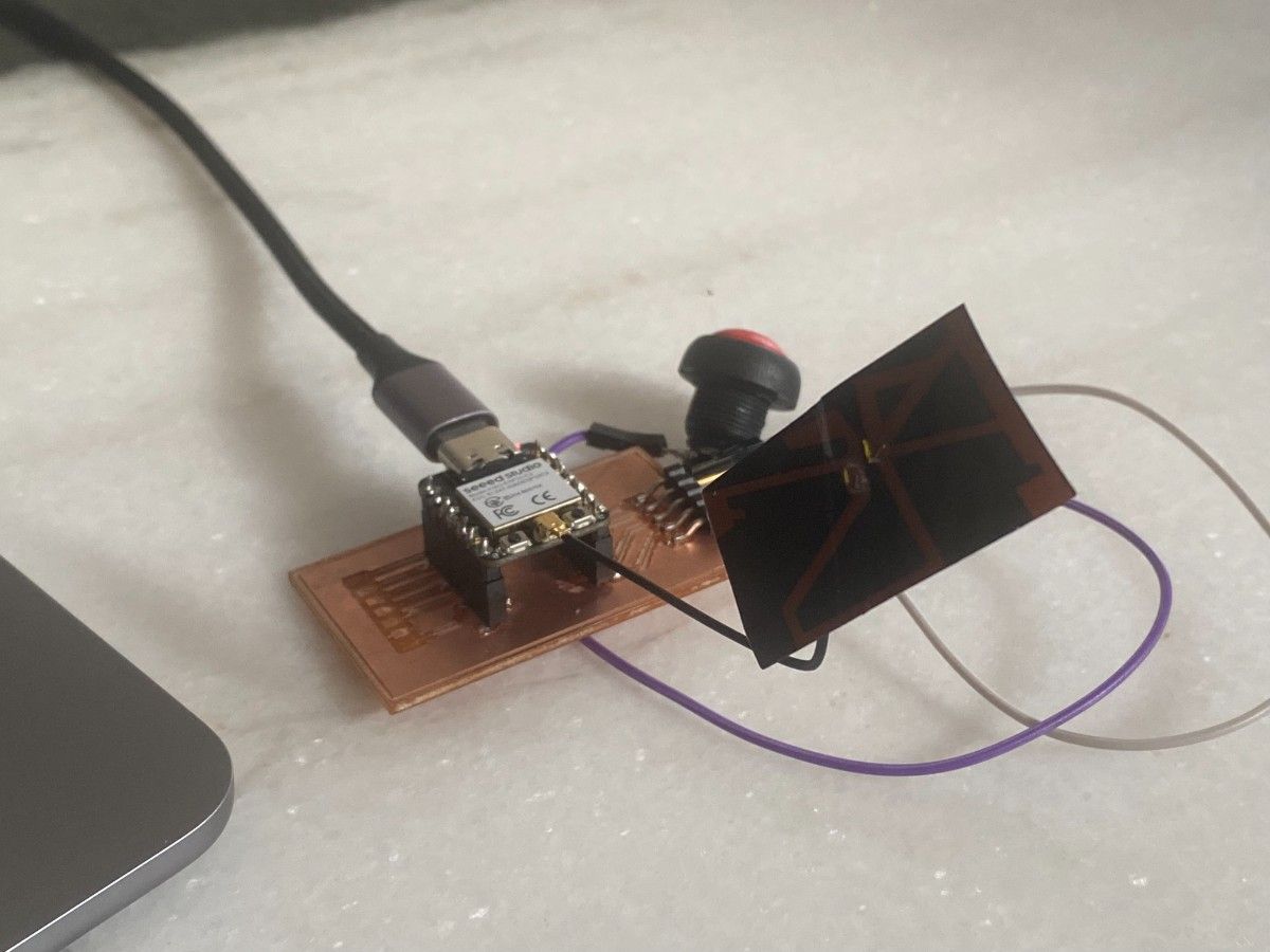
Below is the general testing setup. In this setup, the ESP32 board is not connected to the laptop for communication. The cable is only used for power.
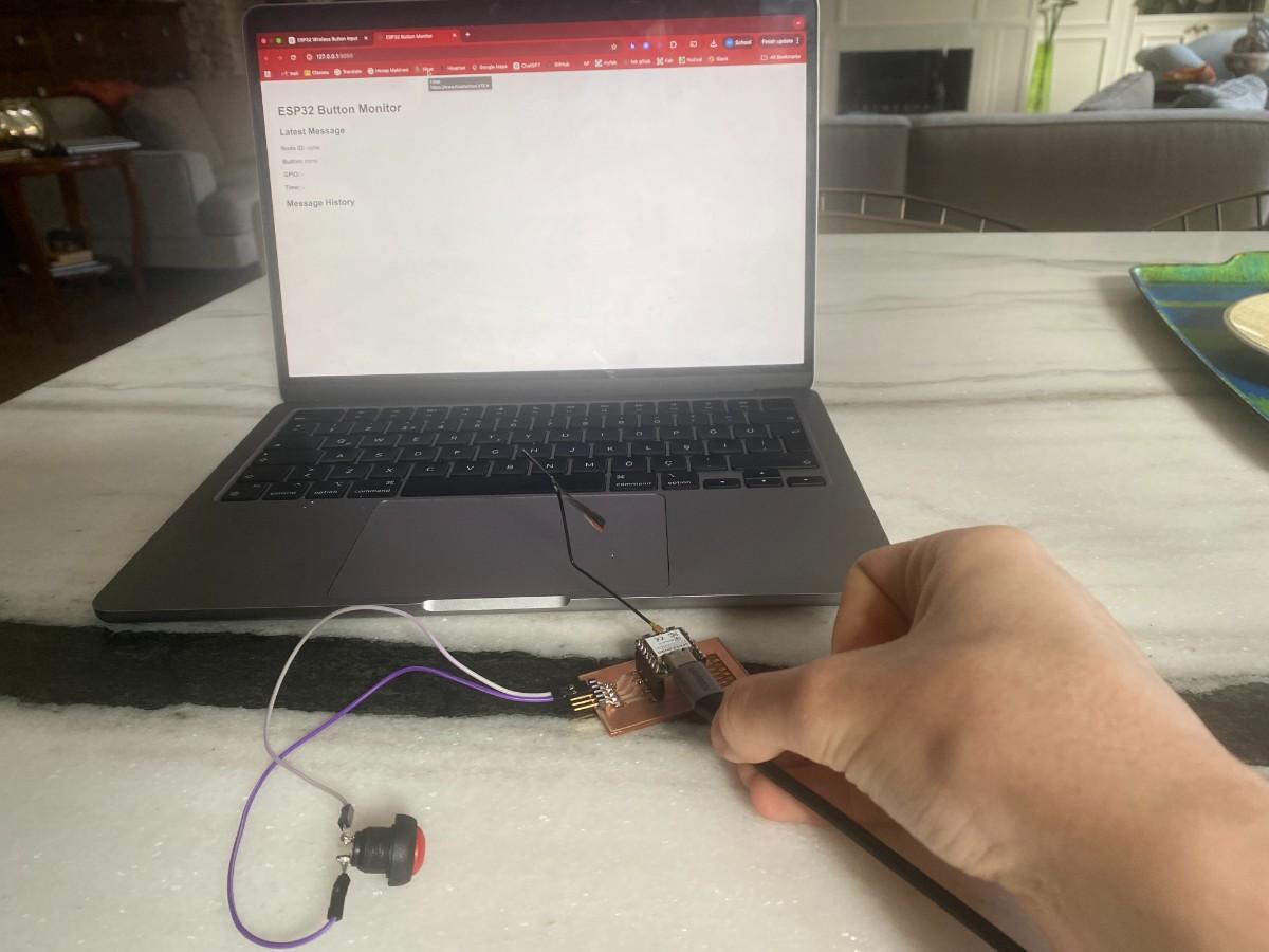
Antenna Placement and Positioning
Since this week depends on wireless communication, antenna placement matters. I made sure that:
- the antenna side of the board was exposed to open space
- the antenna area was not blocked by metal objects
- the USB cable was used only for power, not data transfer during the demonstration
In practice, I oriented the board so the antenna had a clear path to the room rather than being blocked by the desk or my laptop body. For this small-distance local Wi-Fi setup, this was sufficient for a stable connection.
Software Architecture
The software side had two main parts:
- ESP32 firmware
- Python Flask server + browser interface
Communication format
Each button press is sent as a JSON object in the following structure:
{
  "node_id": "button_node_1",
  "button": "Option A",
  "gpio": 2
}
This format makes the communication explicit and readable. It also allowed me to identify the sending node and the specific button pressed.
Step 1 — Setting Up the Laptop Server
To receive data from the ESP32, I created a small Flask web server on my laptop.
Installing Flask
Since my Python installation was managed externally, I used a virtual environment.
python3 -m venv venv
source venv/bin/activate
python3 -m pip install flask
Running the server
I created a Python file called app.py and ran it with:
python app.py
At first, port 5000 was unavailable, so I changed the Flask server to run on port 5050 instead. Once the server started, it showed the following addresses:
http://127.0.0.1:5050http://192.168.1.106:5050
The second one is the important local network address, since the ESP32 needs to send data to my laptop over Wi-Fi.
Finding the local IP address
To determine my laptop’s local IP, I used the terminal command:
ipconfig getifaddr en0
This returned:
192.168.1.106
That address was then used in the ESP32 code as the server destination.
Code
Flask Server Code
The Flask server receives button press messages, stores the latest event, keeps a short history, and serves a browser page that updates automatically.
from flask import Flask, request, jsonify, render_template_string
from datetime import datetime

app = Flask(__name__)

latest_data = {
    "node_id": "none",
    "button": "none",
    "gpio": "-",
    "time": "-"
}

history = []

HTML_PAGE = """
<!DOCTYPE html>
<html>
<head>
    <meta charset="UTF-8">
    <title>ESP32 Button Monitor</title>
    <script>
        async function refreshData() {
            const latestResponse = await fetch('/latest');
            const latest = await latestResponse.json();

            document.getElementById("node").textContent = latest.node_id;
            document.getElementById("button").textContent = latest.button;
            document.getElementById("gpio").textContent = latest.gpio;
            document.getElementById("time").textContent = latest.time;

            const historyResponse = await fetch('/history');
            const history = await historyResponse.json();

            const list = document.getElementById("history");
            list.innerHTML = "";

            history.slice().reverse().forEach(item => {
                const li = document.createElement("li");
                li.textContent = `${item.time} | ${item.node_id} | ${item.button} | GPIO ${item.gpio}`;
                list.appendChild(li);
            });
        }

        setInterval(refreshData, 1000);
        window.onload = refreshData;
    </script>
</head>
<body style="font-family: Arial, sans-serif; padding: 30px;">
    <h1>ESP32 Button Monitor</h1>

    <h2>Latest Message</h2>
    <p><strong>Node ID:</strong> <span id="node">-</span></p>
    <p><strong>Button:</strong> <span id="button">-</span></p>
    <p><strong>GPIO:</strong> <span id="gpio">-</span></p>
    <p><strong>Time:</strong> <span id="time">-</span></p>

    <h2>Message History</h2>
    <ul id="history"></ul>
</body>
</html>
"""

@app.route("/")
def index():
    return render_template_string(HTML_PAGE)

@app.route("/button", methods=["POST"])
def button():
    global latest_data, history

    data = request.get_json(silent=True)

    if not data:
        return jsonify({"status": "error", "message": "No JSON received"}), 400

    latest_data = {
        "node_id": data.get("node_id", "unknown"),
        "button": data.get("button", "unknown"),
        "gpio": data.get("gpio", "unknown"),
        "time": datetime.now().strftime("%H:%M:%S")
    }

    history.append(latest_data.copy())

    if len(history) > 20:
        history = history[-20:]

    print("Received:", latest_data)

    return jsonify({
        "status": "ok",
        "received": latest_data
    })

@app.route("/latest")
def latest():
    return jsonify(latest_data)

@app.route("/history")
def get_history():
    return jsonify(history)

if __name__ == "__main__":
    app.run(host="0.0.0.0", port=5050, debug=True)
Step 2 — Building the Web Interface
The browser interface is intentionally simple. It shows:
- latest received node ID
- latest button pressed
- corresponding GPIO pin
- time received
- recent message history
At the start, before any signal was received, the interface looked empty as expected.
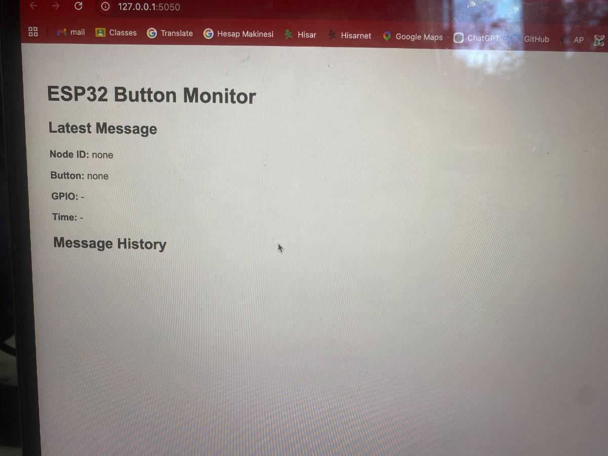
This was helpful because it gave me a clear before/after demonstration: first the empty app, then live updates appearing when I pressed the buttons.
Step 3 — Programming the ESP32 Node
The second major part of the project was the ESP32 code. The firmware had to:
- connect to Wi-Fi
- define the button pins
- detect button presses
- send the correct message to the Flask server
Button Mapping
The four buttons on the PCB were mapped as follows:
- GPIO2 → Option A
- GPIO6 → Option B
- GPIO4 → Option C
- GPIO3 → Option D
ESP32 Firmware
#include <WiFi.h>
#include <HTTPClient.h>

const char* ssid = "YOUR_WIFI_NAME";
const char* password = "YOUR_WIFI_PASSWORD";

// Replace with your computer's local IP address
const char* serverURL = "http://192.168.1.106:5050/button";

int buttons[] = {2, 6, 4, 3};
const char* labels[] = {"Option A", "Option B", "Option C", "Option D"};
int lastState[4];

const char* nodeID = "button_node_1";

void connectWiFi() {
  WiFi.begin(ssid, password);
  Serial.print("Connecting to Wi-Fi");

  while (WiFi.status() != WL_CONNECTED) {
    delay(500);
    Serial.print(".");
  }

  Serial.println();
  Serial.println("Wi-Fi connected!");
  Serial.print("ESP32 IP: ");
  Serial.println(WiFi.localIP());
}

void sendButtonPress(const char* label, int gpio) {
  if (WiFi.status() == WL_CONNECTED) {
    HTTPClient http;
    http.begin(serverURL);
    http.addHeader("Content-Type", "application/json");

    String json = "{";
    json += "\"node_id\":\"" + String(nodeID) + "\",";
    json += "\"button\":\"" + String(label) + "\",";
    json += "\"gpio\":" + String(gpio);
    json += "}";

    int httpResponseCode = http.POST(json);

    Serial.print("Sent: ");
    Serial.print(json);
    Serial.print(" | Response code: ");
    Serial.println(httpResponseCode);

    http.end();
  } else {
    Serial.println("Wi-Fi disconnected, cannot send data.");
  }
}

void setup() {
  Serial.begin(115200);
  delay(500);

  Serial.println("\nESP32-C3 Button Node");
  Serial.println("Press any button (GPIO 2, 6, 4, 3)...\n");

  for (int i = 0; i < 4; i++) {
    pinMode(buttons[i], INPUT_PULLUP);
    lastState[i] = HIGH;
  }

  connectWiFi();
}

void loop() {
  for (int i = 0; i < 4; i++) {
    int current = digitalRead(buttons[i]);

    if (current == LOW && lastState[i] == HIGH) {
      delay(10);
      if (digitalRead(buttons[i]) == LOW) {
        Serial.print(labels[i]);
        Serial.println(" pressed!");
        sendButtonPress(labels[i], buttons[i]);
        lastState[i] = LOW;
      }
    }

    if (current == HIGH && lastState[i] == LOW) {
      lastState[i] = HIGH;
    }
  }
}
How the ESP32 Code Works
1. Wi-Fi connection
The connectWiFi() function connects the board to the local Wi-Fi network and prints the ESP32 IP address to the serial monitor.
2. Input setup
The four button GPIO pins are set as INPUT_PULLUP. This means:
- default state =
HIGH - pressed state =
LOW
This is a clean and common way to read buttons using internal pull-up resistors.
3. Button press detection
In the main loop, the ESP32 constantly checks each button. A press is detected when the signal changes from:
- previous state:
HIGH - current state:
LOW
I also added a small debounce delay of 10 ms to prevent false triggering.
4. Sending data
When a valid press is detected, the ESP32 creates a JSON string and sends it to the laptop server using an HTTP POST request.
5. Preventing repeated sends while held down
The lastState[] array keeps track of previous button states so that the same press is not transmitted repeatedly while the button remains physically held down.
Demonstration Video
The following video shows the final system in action. In the video, I press a button on the PCB and the command is sent wirelessly to the web app.
Network Addressing
This project also demonstrates the addressing aspect of the assignment.
Network-level addressing
The ESP32 and laptop are on the same local Wi-Fi network. The laptop server is addressed using its local IP:
192.168.1.106
and the full server endpoint is:
http://192.168.1.106:5050/button
Node-level identification
In addition to the IP-based network address, each message includes:
"node_id": "button_node_1"
This means the system can be extended later to multiple wireless nodes, each with a unique ID.
Problems Encountered and Fixes
During the setup process, I ran into several practical issues.
1. Python package installation problem
When installing Flask, pip was not directly available and the system Python environment was externally managed. I solved this by creating a virtual environment and installing Flask there.
2. Port 5000 already in use
Initially, Flask could not start on port 5000 because that port was already being used by another service on macOS. I fixed this by moving the server to port 5050.
3. Finding the correct server address
The ESP32 cannot use 127.0.0.1, because that refers to itself rather than my laptop. I had to find my laptop’s local IP address and use that in the serverURL.
4. Matching communication and hardware
I made sure that the server endpoint, Wi-Fi credentials, and button mapping all matched the actual physical board and test environment.
What I Learned
This week helped me understand how to connect embedded hardware to a networked software system in a clear end-to-end way.
I learned how to:
- use the ESP32 as a Wi-Fi-enabled node
- send structured JSON data over HTTP
- run a lightweight local server on a laptop
- build a browser-based monitoring interface
- connect physical inputs to a remote digital output
- think about network addressing at both the device and message level
Most importantly, I built a complete system where a physical user action on a custom PCB directly affects a remote web interface in real time.
Reflection
This assignment was a very good bridge between electronics, embedded programming, and networking. Instead of treating the PCB as an isolated board, I turned it into a connected node that can interact with another system over Wi-Fi.
This feels especially relevant to my final project direction, since it shows how local hardware inputs can be transmitted to a computer-based application. The same general architecture could later be expanded with:
- multiple nodes
- more complex message types
- display outputs
- game or quiz interactions
- live browser control panels
Overall, I successfully completed the assignment by creating a wireless ESP32-based node with local button inputs and a remote web-based output interface.
Group assignment
You can check our group project here
Files
- PCB Design in week 6
- Download Source Code