Group Assignment
This week’s assignment was completed as part of a group project. Our team contributed to the construction of BLOT, an open-source drawing machine originally created by Hack Club. During Fab Academy Machine Building Week 2026, teams from Aalto Fablab in Espoo, Finland and Hisar Fablab in Istanbul, Turkey collaborated to build and document the machine together across two labs.
You can find the full group documentation here: https://academany.fabcloud.io/fabacademy/2026/labs/hisar/site/
Hero Shot
My Individual Contribution
My individual contribution focused on the enclosure and system layout of the machine. I designed and developed the part that turns the mechanism into a more complete and usable system: the press-fit laser-cut enclosure, the base plate, the paper area, and the general internal layout showing where the electronics, cables, and working zones should go.
The motion system was already the main functional core of the machine, but it still needed a structure around it to become a more organized and practical machine. My goal was to create a housing that would make the plotter cleaner, more stable, easier to use, and visually more complete.
More specifically, I worked on:
- designing the laser-cut press-fit enclosure
- planning the overall layout of the machine
- deciding where the electronics would sit
- thinking about how the cables should be routed
- designing the paper area and front base plate
- making the system more compact and easier to interact with
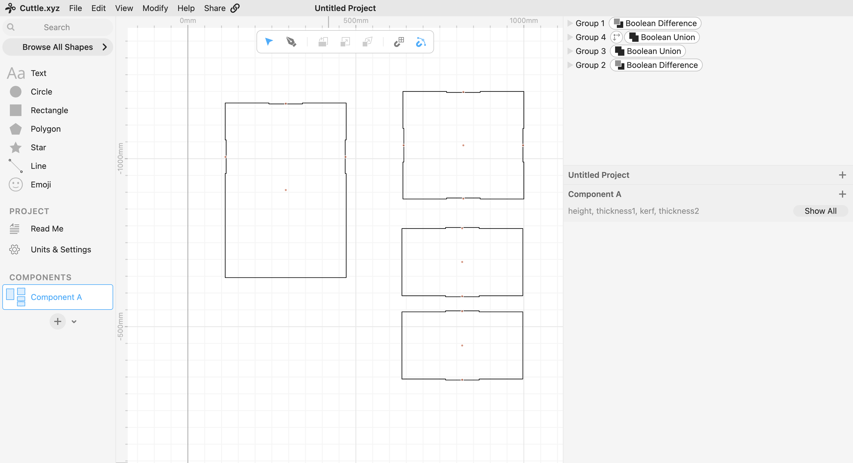
Design
I designed the enclosure as a simple press-fit box system made from laser-cut sheet material. I wanted it to be easy to fabricate and assemble, while also fitting the machine properly without interfering with the motion system. At the same time, I did not want to fully close the machine, because it still needed to be observable and accessible during testing. For that reason, I kept the front side open and extended the base plate forward so the paper could be placed clearly under the pen mechanism.
A major part of my work was not just making a box, but thinking about the system layout. The enclosure needed to organize the whole machine. That meant considering where the electronics would go, how the cables would travel, how much internal space the mechanism needed, and how the user would place and access the paper. I tried to make the internal arrangement as clean as possible so that the machine would feel intentional rather than improvised.
Another important design decision was the base plate and paper placement. The machine needed a clear and flat area where paper could be taped down securely. Instead of placing paper somewhere loosely under the machine, I designed the base plate to extend outward from the enclosure so the drawing zone would be clearly defined. This made the machine much easier to use and also improved the overall presentation of the build.
Fabrication and Assembly
Below is the enclosure during early assembly. This shows the basic press-fit structure before the machine was fully integrated inside it.
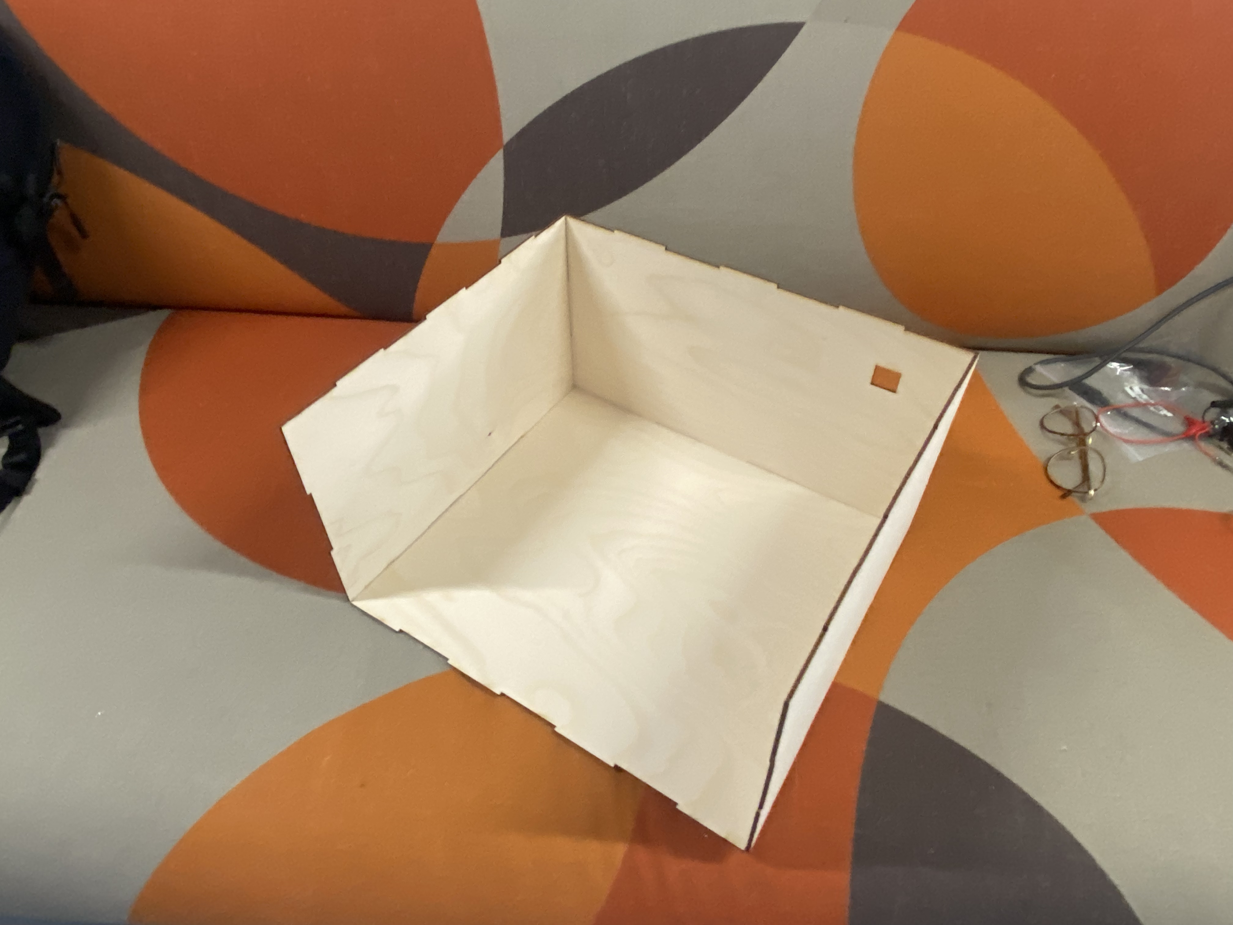
At this stage, the main idea was already visible: a top panel, side walls, and a lower platform that would define the working area of the machine. The press-fit design made the structure easy to assemble and well suited to digital fabrication. It also gave the machine a clear physical boundary instead of leaving all parts exposed on the table.
In the image below, the motion system has been installed inside the enclosure. This view shows how the enclosure frames the mechanism while still leaving enough open space in the front for the drawing area.
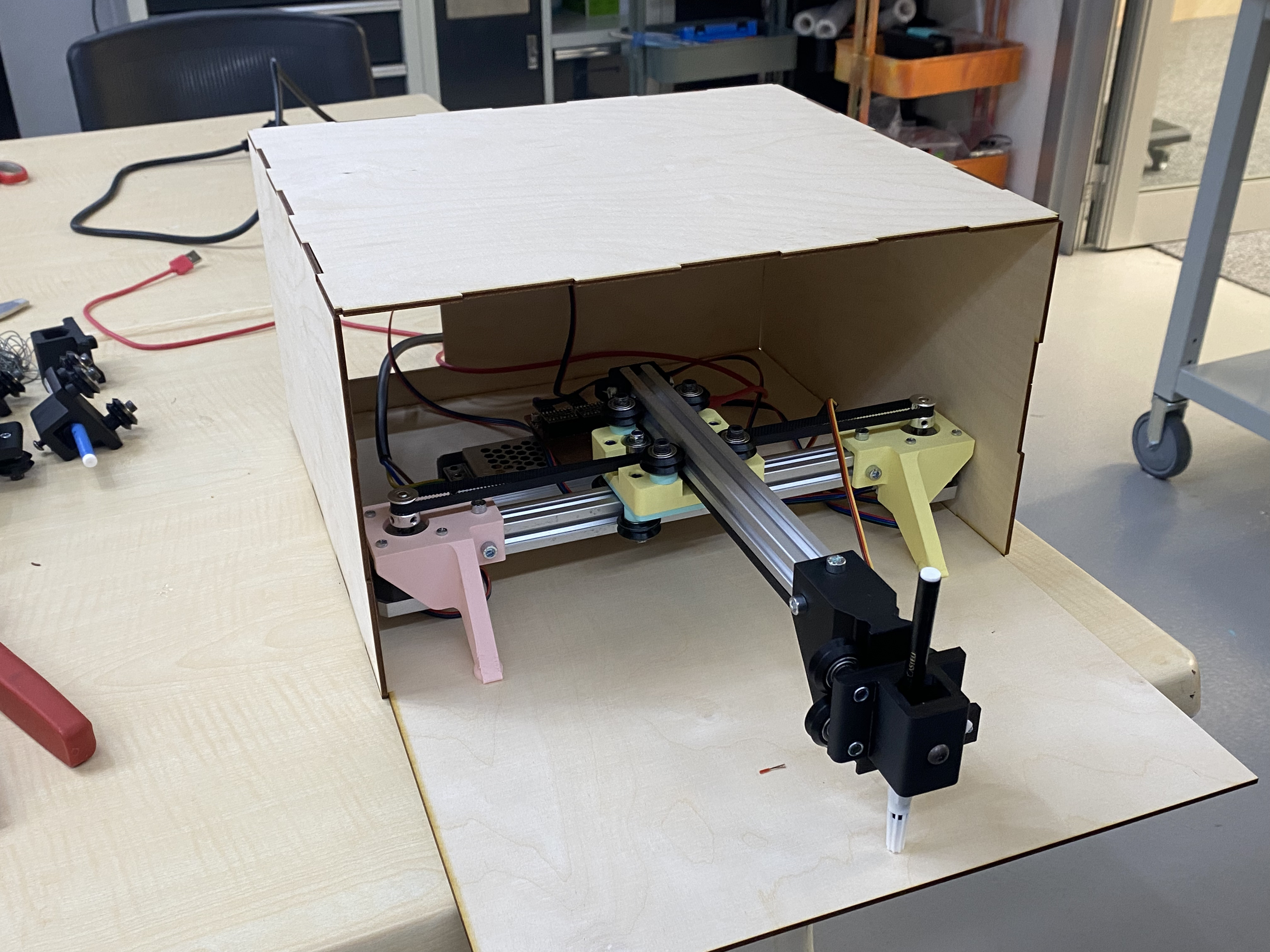
This was an important stage because it showed whether the enclosure dimensions and overall layout were working in practice. The internal mechanism fit inside the housing while the drawing area remained visible and accessible. The side panels and top cover gave the system a more complete form, while the open front allowed easy observation of the machine during operation.
Final Product
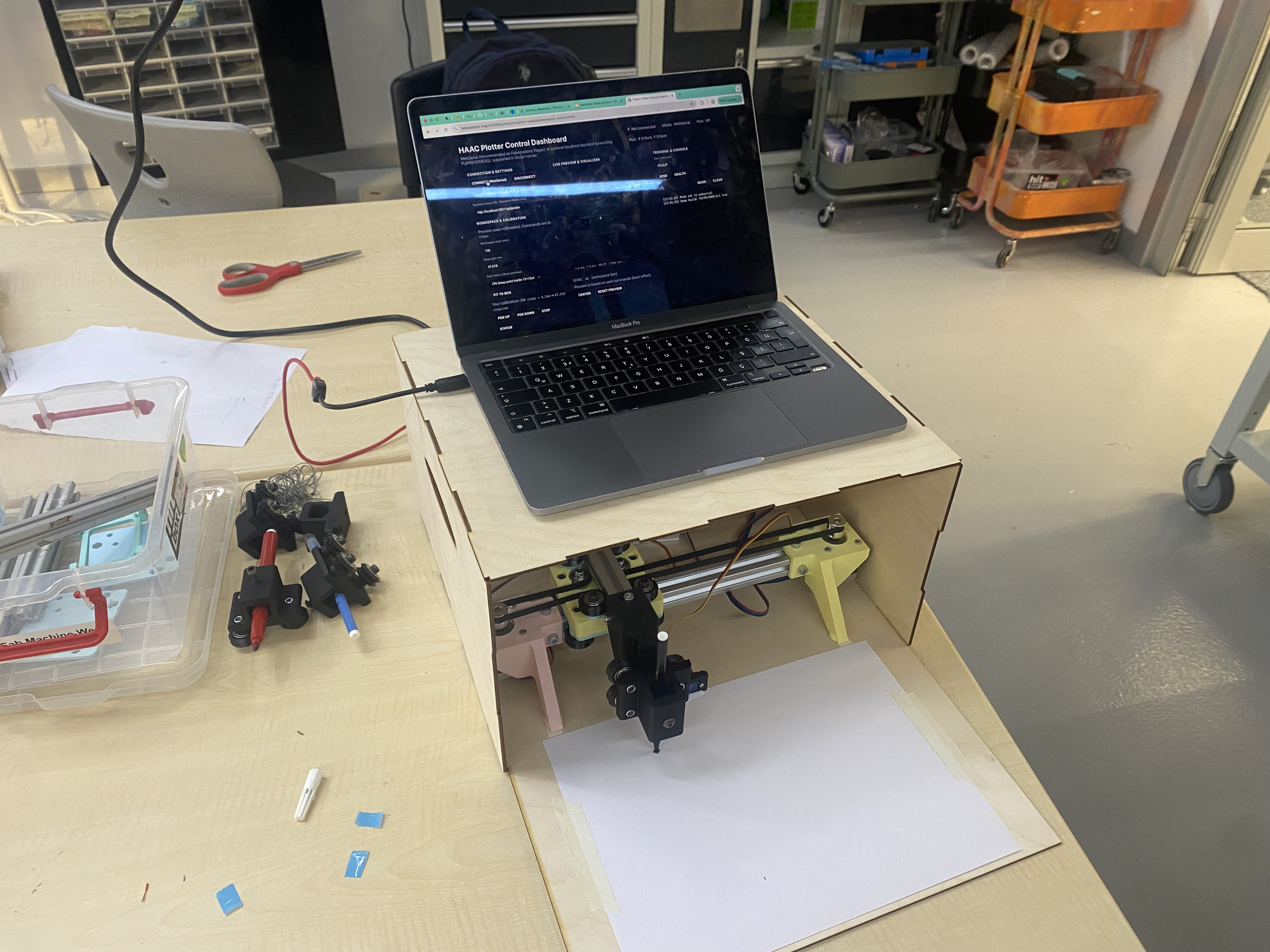
The photo below shows the full machine with the paper area prepared and the system set up for use.
This image also shows something I liked about the final design: the top surface of the enclosure could act as a practical platform during testing. It helped the setup feel more integrated, since the control laptop could sit directly above the machine while the mechanism worked below. This was not the primary goal at the beginning, but it became a useful part of the final setup.
The following image shows the machine during use, with the pen plotting on the paper.
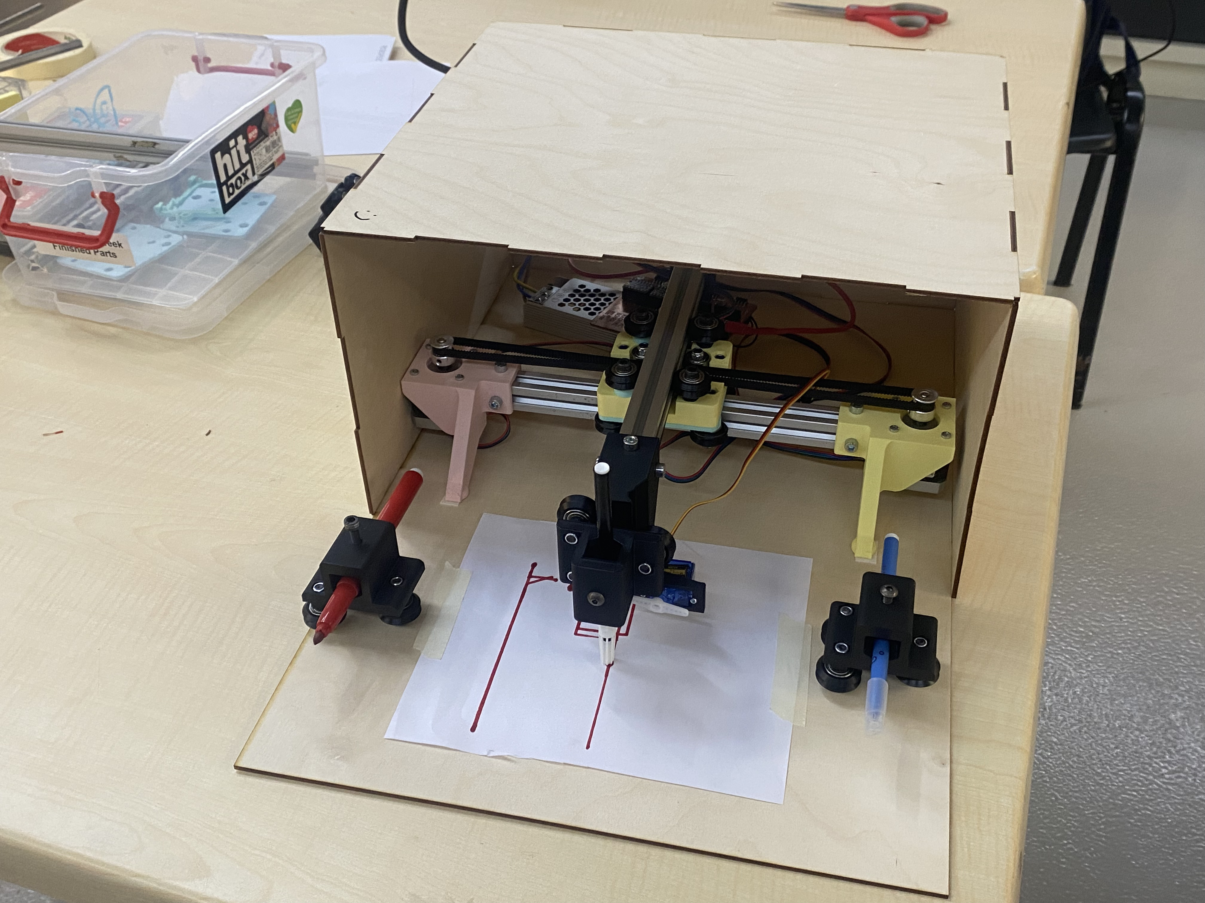
This was the point where the enclosure stopped being just a structural idea and became part of a functioning system. The machine now had a clear outer body, a defined work area, internal space for the mechanism and electronics, and a layout that supported actual operation.
Overall, I think my contribution was important because it helped transform the plotter from a mechanism into a more coherent machine. The enclosure, base plate, paper area, and internal layout brought the different parts together physically and made the whole project more organized, usable, and understandable.
Reflection
What worked especially well in this part of the project was the simplicity of the construction. The press-fit approach made fabrication and assembly straightforward. The open-front design kept the machine easy to access. The base plate extension made paper placement much more intuitive. The enclosure also helped the entire project feel much more complete, almost like a product-like system instead of a loose prototype.
One of the main challenges was balancing protection and accessibility. A closed enclosure could have looked cleaner, but it would have made debugging and testing harder. On the other hand, if the structure was too open, it would not really function as an enclosure. I had to find a middle ground where the machine remained usable, visible, and practical without losing the benefit of having a defined outer structure.
Another challenge was designing around a real moving mechanism. The housing could not interfere with the gantry, pen holder, belts, or wires. So the layout had to consider both the static parts of the machine and the moving parts together. This made the work much more than just designing a box; it was really about building a functional spatial arrangement around an active machine.
This week helped me understand that machine design is not only about motors, movement, and code. A working machine also needs a thoughtful physical layout: where components go, how cables are managed, how the user interacts with the system, and how the structure supports both function and clarity. Through this contribution, I got more experience in designing around a real machine system and thinking about usability, fabrication, and organization at the same time.