Individual Assignment
For this week, I developed a complete application that interfaces a user with an input and output device that I made. The system builds directly on the custom PCB I developed in earlier weeks and turns it into a standalone quiz device controlled through a browser-based application.
My final system has two main parts:
- a computer-side web application for creating and sending quizzes
- a PCB-side embedded application running on my custom ESP32-C3 board with four push buttons and an OLED display
The browser application allows the user to write a custom quiz by entering questions, four answer options, and the correct answer for each question. Once the quiz is sent, the PCB receives the entire quiz wirelessly over Wi-Fi, stores it locally, and runs the full session independently on the device. The user then interacts directly with the PCB using the four physical buttons, while the OLED displays the questions and answer choices. After the quiz is completed, the PCB calculates the score and total time, then sends the final results back to the computer.
This assignment fits the week very well because the application is not only connected to a device I made, but is specifically designed around the physical interface of that device. The web application acts as the authoring and monitoring environment, while the PCB becomes the dedicated embedded quiz player.
Below is the final hardware setup used in the project.
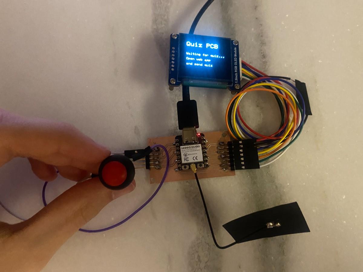
Design and Implementation
I wanted this week’s project to connect strongly with my final project direction. In earlier weeks, I had already tested the two main hardware elements that matter for this system:
- the four-button input interface on my custom PCB
- the OLED display as the visual output interface
I had also already demonstrated wireless communication in Networking and Communications week by sending messages between the ESP32-C3 and a web server on my laptop. For this week, instead of simply sending one button press at a time to a live dashboard, I redesigned the system into a more complete application workflow.
The final interaction model works like this:
- The user creates a quiz in the browser
- The quiz is sent from the computer to the PCB
- The PCB runs the quiz locally without constant screen refreshing or continuous live control
- The user answers directly on the hardware using the four buttons
- The PCB evaluates the answers, calculates score and time, and sends the final results back to the computer
This changed the system from a simple live communication test into a real interactive application.
The browser-side application was written in Python using Flask. I chose Flask because it is lightweight, easy to run locally, and well suited for building a custom interface for communication with the ESP32. The web page includes a quiz builder interface where the user can type a quiz title, create questions, fill in four options, and select the correct answer. It also includes a session status area that shows whether a quiz is waiting for the PCB and later displays the final score and answer history after the device finishes the quiz.
Below is the browser interface used to create and manage quizzes.
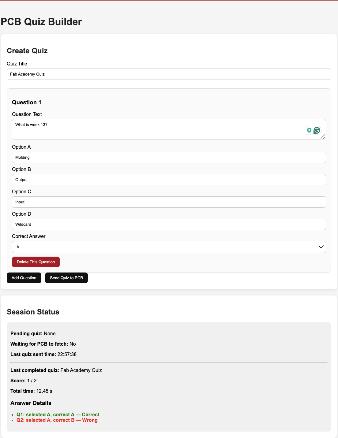
A very important design decision was to stop treating the PCB as a constantly synchronized remote screen. In my earlier version, the ESP32 repeatedly fetched the current question from the server, which meant that the OLED was refreshing too often. I changed the architecture so that the PCB only listens silently in the background for a new quiz package. Once a quiz is available, it downloads the entire quiz once, then runs everything locally on the device. This made the interface much cleaner and more realistic as an embedded application.
The overall structure of the system is:
- browser application for quiz creation
- Flask server for sending quiz data and receiving results
- ESP32-C3 custom PCB as the embedded device
- OLED as the output display
- four push buttons as the user input interface
The web interface is therefore the application layer, while the PCB is the dedicated interactive hardware.
To make the device-side implementation robust and simple, I used a custom text-based protocol rather than relying on more complicated JSON parsing on the microcontroller. The server packages the quiz into a plain text structure, and the ESP32 parses that text, stores the questions locally, and then presents them on the OLED. This made the communication easier to debug and more reliable for the assignment.
The key part of the computer-side code is the function that converts the user-created quiz into a package that the ESP32 can download:
    def make_quiz_package(quiz):
        lines = []
        lines.append("QUIZ")
        lines.append(f"TITLE={quiz['title']}")
        lines.append(f"COUNT={len(quiz['questions'])}")

        for q in quiz["questions"]:
            safe_parts = [
                q["question"].replace("|", "/").replace("\n", " "),
                q["optionA"].replace("|", "/").replace("\n", " "),
                q["optionB"].replace("|", "/").replace("\n", " "),
                q["optionC"].replace("|", "/").replace("\n", " "),
                q["optionD"].replace("|", "/").replace("\n", " "),
                q["correct"]
            ]
            lines.append("Q|" + "|".join(safe_parts))

        lines.append("END")
        return "\n".join(lines)
This function is important because it defines the communication format between the computer and the PCB. Each question is converted into one line, and the entire quiz is bundled into a lightweight package that the ESP32 can fetch over HTTP.
On the embedded side, the ESP32 checks in the background whether a new quiz is available. When it finds one, it stores the full quiz locally and then starts the quiz session. This is the key device-side logic:
    bool gotQuiz = fetchQuizPackage();

    if (gotQuiz) {
      runQuizLocally();
      sendResults();
      resetQuizData();
      showListeningScreen();
    }
This part of the code is central to the final behavior of the project. It ensures that the PCB does not constantly refresh the screen while waiting. Instead, it quietly polls for a quiz, then only updates the display once the quiz is actually received. After that, the device becomes a self-contained quiz runner.
The local quiz execution is handled entirely on the PCB. Each question is displayed on the OLED, the user answers with one of the four buttons, and the result is shown immediately before moving on to the next question. The structure is:
    for (int i = 0; i < questionCount; i++) {
      showQuestion(i);
      char answer = waitForAnswer();
      selectedAnswers[i] = answer;

      if (answer == correctAnswers[i]) {
        showCenteredMessage("Correct!", "Nice", 0x07E0);
      } else {
        String msg = "Ans: ";
        msg += correctAnswers[i];
        showCenteredMessage("Wrong", msg, 0xF800);
      }

      delay(900);
    }
This loop is what turns the hardware into an interactive application. The OLED is not just showing a test message anymore; it is actively guiding the user through a complete quiz session. The four push buttons now function as the main physical input interface for the application.
After the final question, the PCB calculates the score and total session time, then sends everything back to the server. The results payload includes the quiz title, score, total number of questions, time in milliseconds, and a record of the answers. The server then parses the results and displays them in the browser interface.
This final data return step is what completes the full two-way interaction:
- computer sends quiz to hardware
- hardware runs the application independently
- hardware sends final session results back to the computer
That full cycle is what I consider the main achievement of this week.
Demonstration and Reflection
The first video below shows the browser-side workflow where I create the quiz in the web interface. This is the authoring stage of the application, where the user enters the questions and prepares the dataset that will be sent to the PCB.
The second video shows the final demonstration of the complete system. In this sequence, the quiz is sent to the PCB, the OLED displays the questions, the physical buttons are used to answer, and the application behaves as a real interactive device.
This week was a very important step for my final project because it brought together multiple threads from previous assignments into a single coherent application:
- custom electronics design
- embedded programming
- display output
- physical button input
- wireless communication
- computer-side application design
What I like most about this result is that the system now behaves like an actual product prototype rather than a collection of separate technical tests. The browser application has a clear purpose, the hardware has a clear user interaction model, and the communication between the two parts supports a meaningful workflow.
This assignment also gave me a much clearer direction for my final project. My long-term goal is to develop a quiz-based learning device where questions can be managed from a web interface, displayed on a custom handheld PCB, answered using physical controls, and later expanded with more advanced features such as explanations, score tracking, custom datasets, and AI-assisted question generation from notes. This week provided the first working implementation of that idea.
I also learned several practical lessons during development:
- it is important to separate “listening for data” from “refreshing the user interface”
- embedded systems become much cleaner when the device can act independently after receiving a task
- simple communication protocols are often easier to debug than more complex ones
- the quality of the user experience depends not only on the hardware, but also on the logic of the interaction flow
Overall, I successfully completed the individual assignment by writing an application that interfaces a user with both the input and output devices that I made. The four buttons and OLED on my custom PCB are not just being tested independently; they are now integrated into a functioning interactive application controlled by a custom web interface.
Group Assignment
You can find our group assignment here