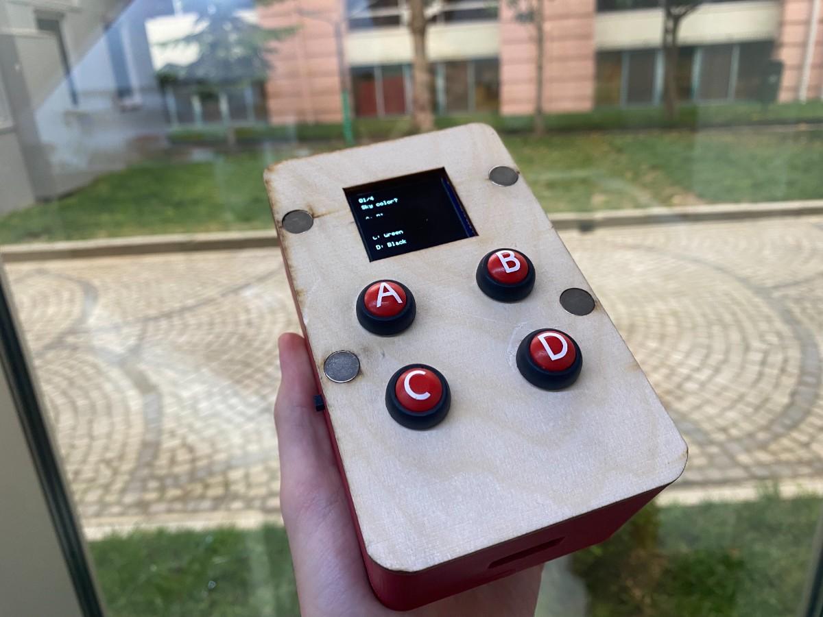
Hero Shot
This week I focused on integrating the electronic, mechanical, interface, wiring, power, and networking parts of my final project into one functional device. My goal was not only to make each part work separately, but to make the whole system behave like a finished product.
My final project is called Duello. Duello is a wireless competitive learning device for middle school students. Two devices connect over Wi-Fi and allow two players to answer teacher-programmed multiple-choice questions using physical A/B/C/D buttons. The device displays questions, options, scores, round results, and the final winner on a 1.5 inch RGB OLED screen.
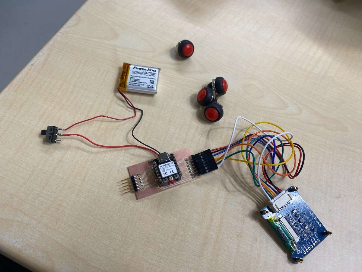
The final integrated device consists of:
- a 3D-printed base
- a laser-cut plywood cover
- four red push buttons
- white vinyl A/B/C/D labels
- a 1.5 inch RGB OLED module
- an ESP32-C3 Super Mini integrated custom PCB
- a 1S 3.7 V 1000 mAh LiPo battery
- an on/off slide switch
- crimped internal wiring
- magnets connecting the base and cover
The base and cover are connected using magnets, so the device can be opened for debugging and maintenance without screws. The final device is approximately 85 mm wide, 140 mm long, and 60 mm high.
System Overview
Duello is made from two main mechanical parts: a 3D-printed base and a laser-cut top cover.
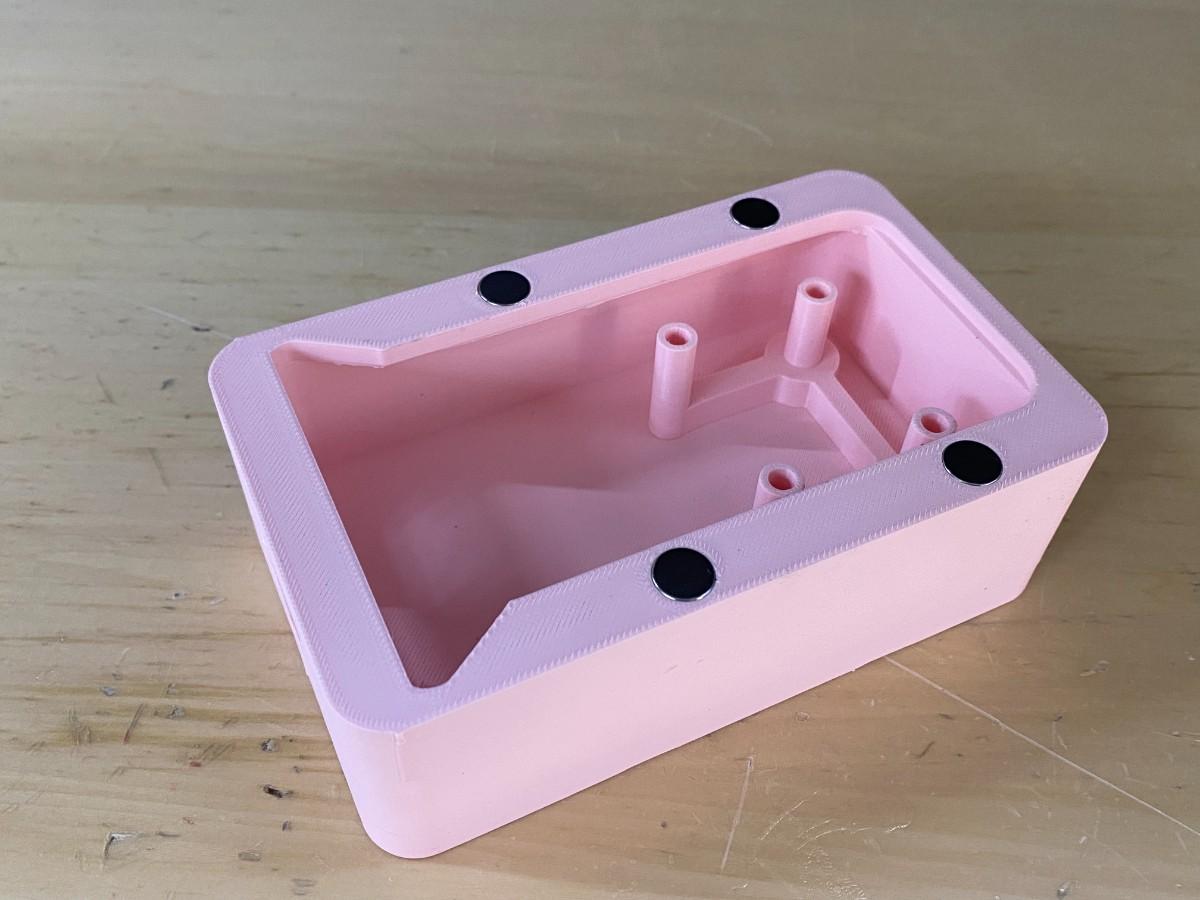
The 3D-printed base is printed using premium red PLA. It holds the main electronics, including the custom PCB, LiPo battery, internal wiring, and OLED support. The OLED stand is integrated directly into the 3D-printed base, so the screen has a fixed position inside the enclosure.
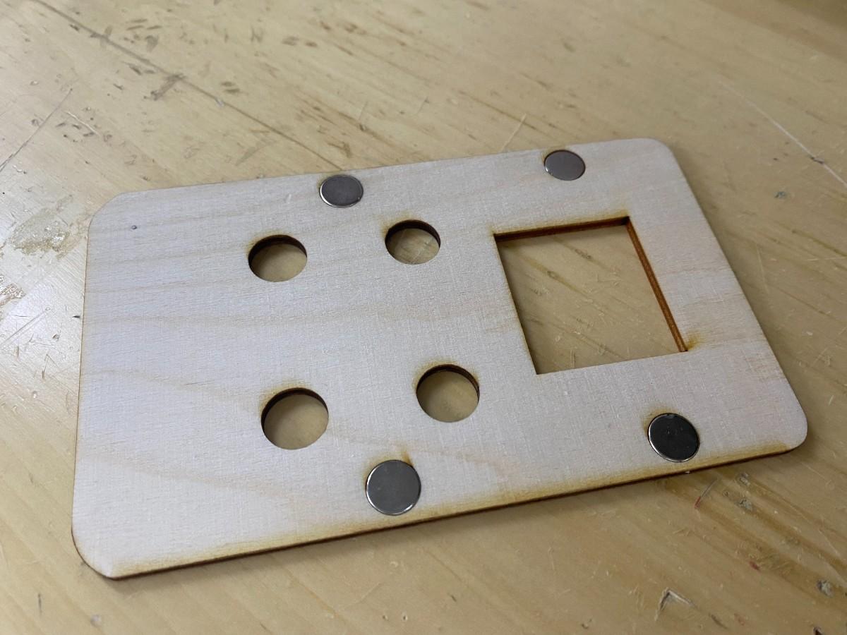
The laser-cut top cover is made from 3 mm plywood. It acts as the main user interface panel. It holds the four push buttons using their own nuts, includes the screen opening, and connects to the base using magnets. The buttons are red, and the A/B/C/D button labels are white vinyl stickers.
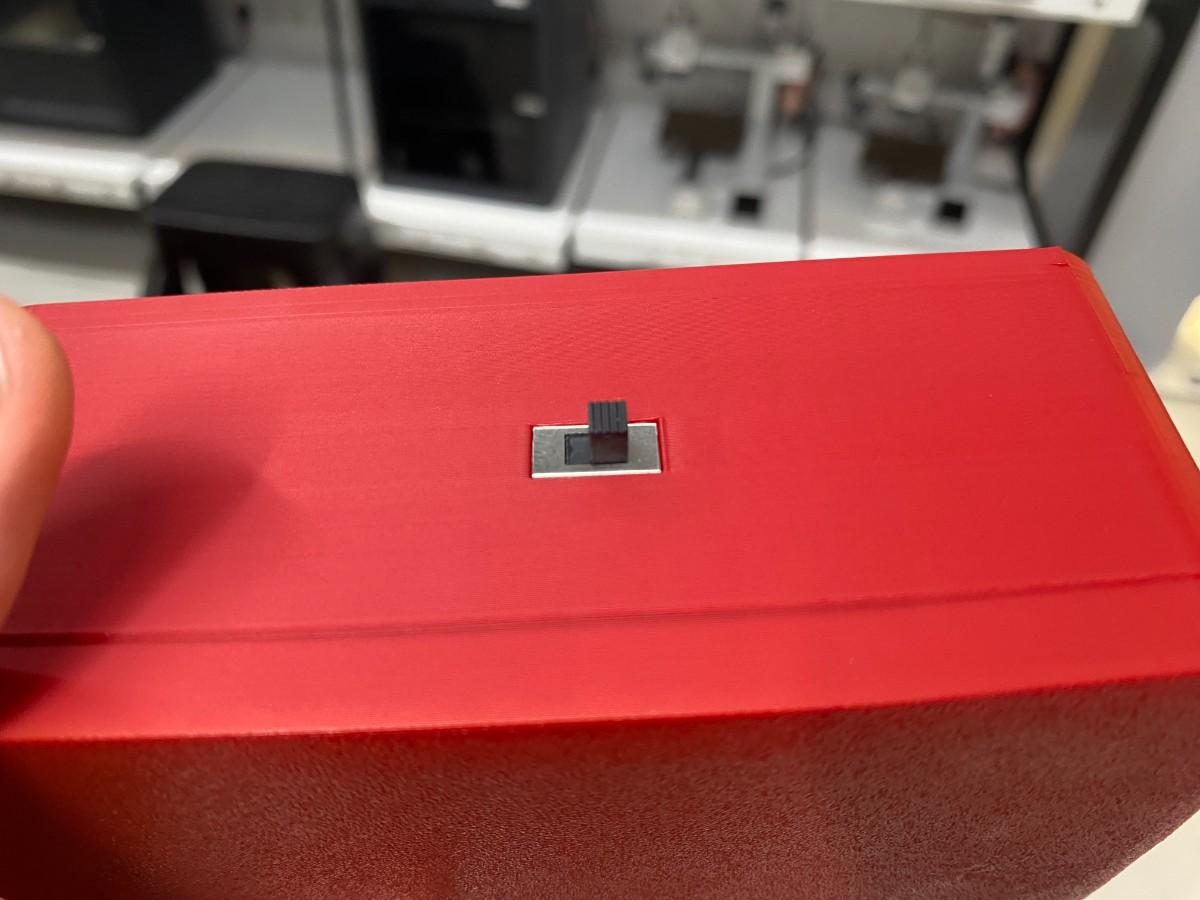
The device is powered by a 1S 3.7 V 1000 mAh LiPo battery. The battery is connected through an on/off slide switch, so the device can be fully turned on and off. The battery connects to the ESP32-C3 board power pads, and the ESP32-C3 board handles power regulation and charging when an external USB power source is connected.
Bill of Materials
| Component | Quantity | Purpose |
|---|---|---|
| ESP32-C3 Super Mini | 1 | Main microcontroller and Wi-Fi module |
| Custom PCB | 1 | Holds ESP32-C3 connections, OLED connector, button inputs, and power connections |
| 1.5 inch RGB OLED module | 1 | Main visual output |
| Red push buttons | 4 | A/B/C/D user input buttons |
| White vinyl stickers | 4 labels | Button labels |
| 1S 3.7 V 1000 mAh LiPo battery | 1 | Portable power source |
| Slide switch | 1 | Turns device on and off |
| 100 µF 25 V capacitor | 1 | Power stabilization near battery input |
| 3D printed base | 1 | Main enclosure body |
| 3 mm plywood cover | 1 | Top user interface panel |
| Magnets | 8 total | 4 in base and 4 in cover |
| 2.80 mm insulated female Faston connectors | Multiple | Button wiring |
| 7-pin PH connector / crimped OLED cable | 1 set | OLED wiring |
| Jumper wires | Several | Internal PCB connections |
| Double-sided 3M mounting tape | 1 piece | PCB mounting |
Mechanical Integration
Base and Cover System
The enclosure was designed as a two-part system. The bottom part is a 3D-printed base, and the top part is a laser-cut plywood cover.
I chose this combination because each fabrication method was useful for a different purpose. The 3D-printed base gave me more control over the internal structure. I could create the walls, internal layout, OLED stand, battery space, PCB placement area, and cable routing space directly in the CAD model.
The laser-cut plywood cover was better for the user interface because it created a flat and clean front panel. The button holes and screen opening could be cut precisely, which helped the buttons and OLED align with the outside of the device.
The base was designed in Fusion 360. The cover geometry was exported from Fusion 360 and then edited in Adobe Illustrator before laser cutting. The base was printed on the Bambu Lab A1, and the cover was cut on the xTool P3.
Magnet Integration
The cover and base are connected using magnets instead of screws. There are 4 magnets in the base and 4 magnets in the cover. Each magnet is approximately 1 cm in diameter.
The magnets are press-fit into the parts. The tolerance for the 3D print and the kerf compensation for the laser-cut cover were accurate enough that the magnets fit securely.
This connection system is useful because the enclosure can be opened for debugging, wiring changes, and maintenance. At the same time, the magnets are strong enough to keep the cover attached during normal use.
During assembly testing, I checked that:
- the cover aligned with the base
- the magnets pulled the cover into the correct position
- the cover could be removed without tools
- the cover did not fall off during normal handling
- the internal cables did not block the cover from closing
Electronics Integration
Custom PCB Placement
The custom PCB is placed inside the 3D-printed base. It is based on the ESP32-C3 Super Mini and connects the OLED screen, button inputs, battery power, and ground connections.
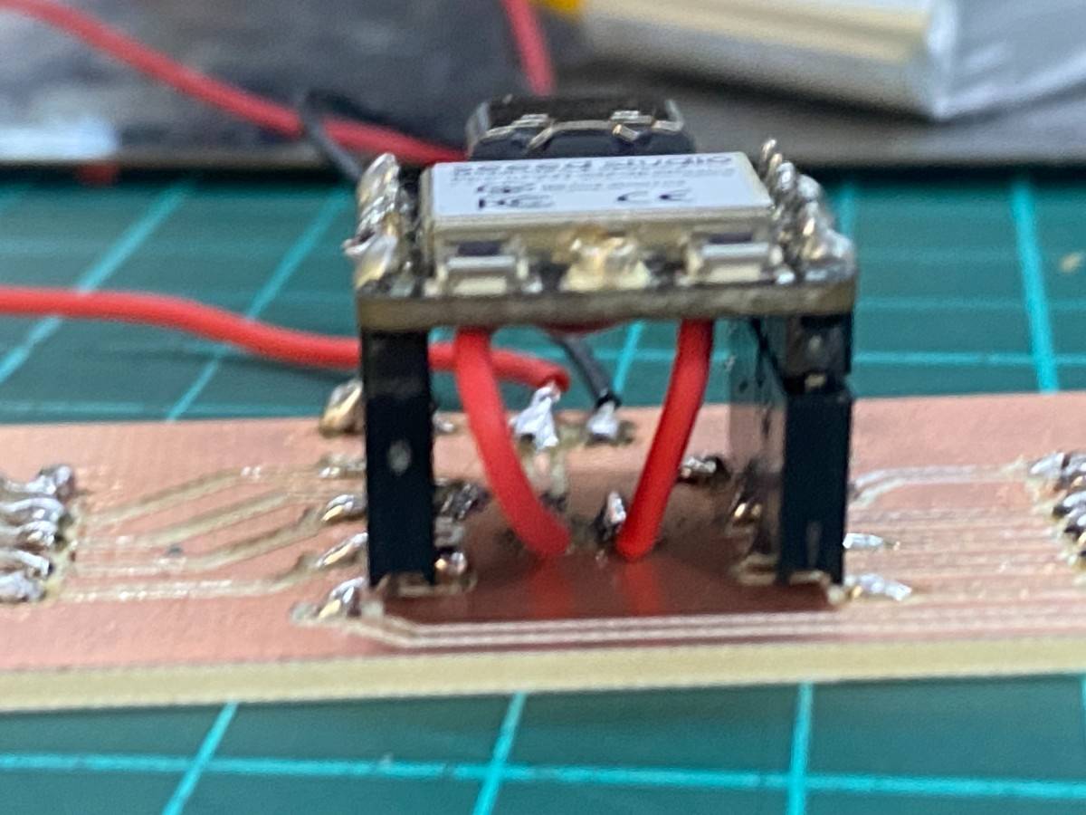
The PCB was designed to keep the main electronics in one compact area. This made the internal layout cleaner because the OLED and buttons could connect to the PCB instead of being wired directly to the ESP32-C3 pins one by one.
The PCB is mounted inside the base using double-sided 3M mounting tape. This was a simple and low-profile mounting method that kept the PCB fixed inside the enclosure while avoiding extra screws or standoffs.
The PCB integrates:
- ESP32-C3 Super Mini connections
- OLED SPI pins
- button input pins
- common ground connections
- power input connections
- battery-related power routing
OLED Screen Integration
The project uses a 1.5 inch RGB OLED module with a 7-pin SPI interface. The OLED operates at 3.3 V.
The OLED is mounted on a 3D-printed stand that is part of the base. This helped keep the screen aligned with the laser-cut cover opening. The OLED wiring is made using a 7-pin PH connector on the OLED side and crimped/jumper-style connections to the PCB side.
The OLED displays:
- connection status
- current question
- answer options
- scores
- selected answer
- round result
- final winner
The OLED integration was important because the screen is the main feedback system of the device. The player needs to clearly see the question and options while using the physical buttons.
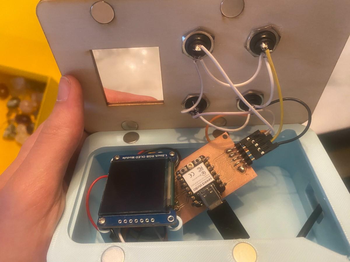
Button Integration
The four red push buttons are mounted directly onto the laser-cut plywood cover. Each button is inserted through its circular hole and tightened using its own nut from the back side of the cover.
This made the buttons mechanically strong because they are not held by glue or friction. The button nuts clamp the button bodies to the wooden panel.
Each button has two terminals. One terminal goes to a GPIO input on the PCB, and the other terminal connects to ground.
The buttons use a shared common ground. This means the ground terminals of all four buttons are interconnected, and only one main ground line returns to the PCB. This reduced the number of ground wires going back to the board and made the internal wiring cleaner.
The button connections use Tam İzoleli Dişi Faston Tip Kablo Ucu 2.80mm connectors. These crimped Faston connectors make the button wiring more secure and more serviceable than directly soldering every wire permanently.
The button pins are read in the code using INPUT_PULLUP. This means each input normally reads HIGH, and when the button is pressed it connects to ground and reads LOW.
The button mapping is:
| Button | GPIO |
|---|---|
| A | GPIO2 |
| B | GPIO6 |
| C | GPIO4 |
| D | GPIO3 |
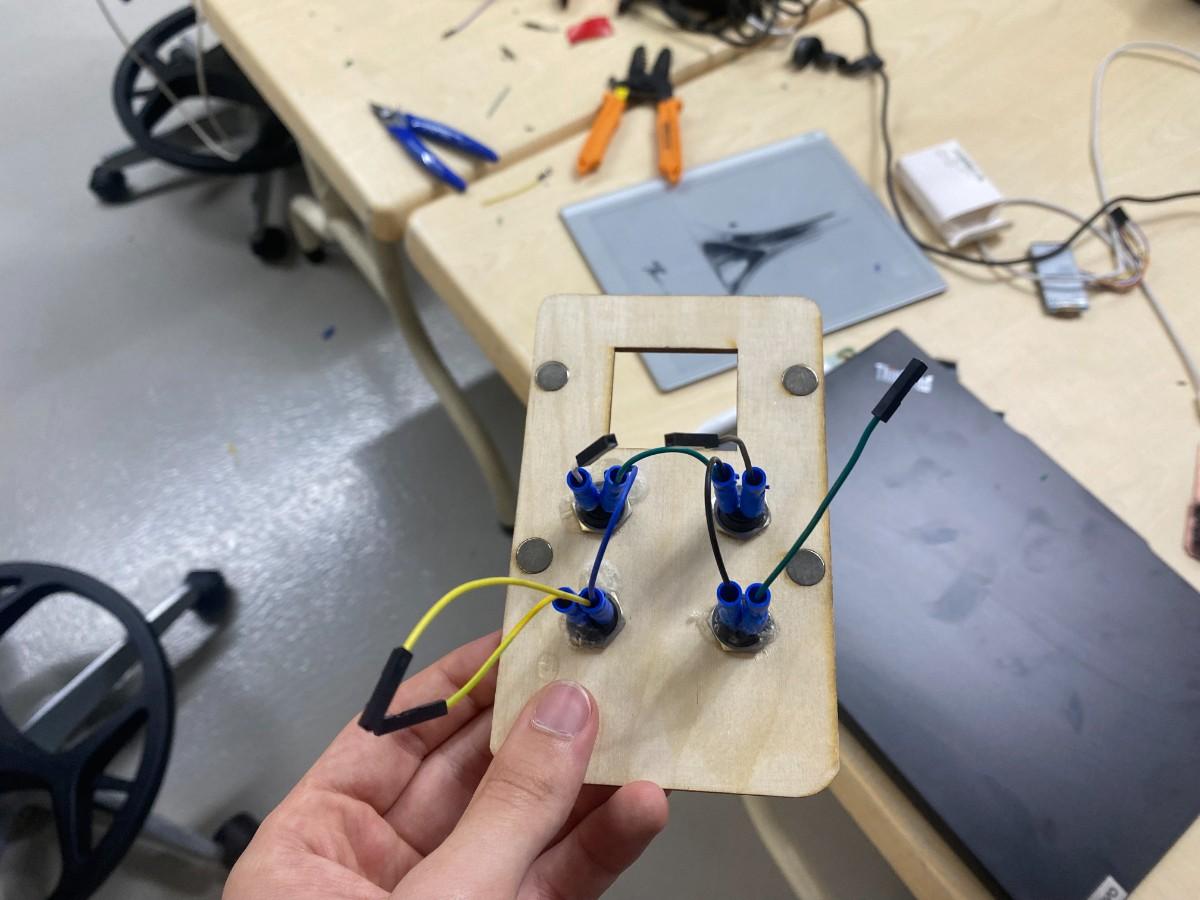
Cable Integration
Cable integration was one of the most important parts of this week. The device has a removable cover, but the buttons are attached to the cover while the PCB is inside the base. This means the wiring has to be long enough to open the device, but short enough to fit cleanly inside when the cover is closed.
To make the wiring more reliable, I used crimped connectors for both the buttons and the OLED.
The button wiring uses:
- 2.80 mm insulated female Faston connectors on the button side
- shared ground wiring between the buttons
- signal wires routed individually to the PCB
- crimped cable ends for stronger connections
The OLED wiring uses:
- 7-pin PH connection on the OLED side
- crimped/jumper-style connections to the PCB
This improved system integration because the electronics were not just temporarily connected on a breadboard. The wiring became part of the final packaged device.
Power Integration
The final version is powered by a 1S 3.7 V 1000 mAh LiPo battery.
The power path is:
1S 3.7 V LiPo battery
        ↓
on/off slide switch
        ↓
ESP32-C3 Super Mini power pads
        ↓
ESP32-C3 board regulation
        ↓
custom PCB, OLED, buttons, and Wi-Fi system
The slide switch allows the whole device to be turned on and off. This is important because the device is portable and battery-powered.
A 100 µF 25 V capacitor is placed near the battery input and GND. This helps stabilize the power input, especially because Wi-Fi devices can create short current spikes.
The ESP32-C3 board handles battery charging when an external power source is connected through USB. This means I did not need to design a separate battery charging circuit for this version.
Power Estimate
The main power consumers are the ESP32-C3 and the RGB OLED. The buttons do not use significant power because they only connect GPIO pins to ground when pressed.
| Part | Estimated Current | Notes |
|---|---|---|
| ESP32-C3 normal operation | 40–100 mA | Depends on code and Wi-Fi use |
| ESP32-C3 Wi-Fi peaks | 250–350 mA peak | Short current spikes during wireless communication |
| 1.5 inch RGB OLED | 40–120 mA | Depends on screen brightness and pixels lit |
| Four push buttons | Very small | Only GPIO pull-up behavior |
| Total typical estimate | 90–220 mA | Normal use |
| Possible peak estimate | 350–500 mA | Wi-Fi peak and bright OLED |
With a 1000 mAh LiPo battery, the rough runtime estimate is:
1000 mAh / 220 mA ≈ 4.5 hours
In real use, the runtime may be lower because of Wi-Fi peaks, OLED brightness, battery condition, and regulator losses. However, the battery capacity is enough for classroom demo use.
Networking Integration
Duello uses two ESP32-C3 devices communicating over Wi-Fi.
For the current prototype:
- Player 1 device acts as the host/server.
- Player 1 creates a local Wi-Fi access point named
FABLAB. - Player 2 connects to this Wi-Fi network.
- Player 2 requests the game state from Player 1.
- Player 2 submits its answers to Player 1.
- Player 1 controls the quiz state, timing, scoring, and round progression.
The system uses HTTP communication. The host device uses server routes such as:
/statefor sending the current game state/answerfor receiving the second player’s answer
The player device polls the host for updated state and sends its selected answer back to the host. This allows both devices to display the same quiz question and results.
There is no external antenna. The devices use the ESP32-C3 Super Mini Wi-Fi directly. In testing, the devices worked reliably within the Fab Lab range.
Software Integration
The code is divided into two roles:
Host Device
The host device:
- creates the Wi-Fi access point
- starts the local web server
- stores the quiz questions
- controls the current question
- handles Player 1 button input
- receives Player 2 answers
- calculates scores
- controls phase changes
- sends game state to Player 2
- shows the same game feedback on its OLED
Player Device
The player/client device:
- connects to the host Wi-Fi network
- requests the current game state
- displays the current question and options
- handles Player 2 button input
- sends Player 2 answer to the host
- displays round results and final score
The game has four main phases:
| Phase | Meaning |
|---|---|
| 0 | Waiting to start |
| 1 | Question active |
| 2 | Showing round result |
| 3 | Final score screen |
The scoring system gives up to 10 points for a correct answer. The points decrease by 1 for each second that passes. Incorrect answers or missing answers receive 0 points.
Assembly Process
The assembly process was:
- 3D print the red PLA base.
- Laser cut the 3 mm plywood cover.
- Vinyl cut the white A/B/C/D labels.
- Insert the magnets into the 3D-printed base.
- Insert the matching magnets into the plywood cover.
- Place the OLED module on the integrated 3D-printed stand.
- Mount the four push buttons into the laser-cut cover.
- Tighten the button nuts from the back side of the cover.
- Crimp the button wires using 2.80 mm insulated female Faston connectors.
- Interconnect the button ground terminals.
- Route one shared ground line back to the PCB.
- Route each button signal wire back to the PCB.
- Connect the OLED using the 7-pin connector cable.
- Connect the LiPo battery through the slide switch.
- Add the 100 µF capacitor near battery input and GND.
- Mount the PCB inside the base using double-sided 3M mounting tape.
- Close the cover and check magnet alignment.
- Turn the device on using the slide switch.
- Test OLED, buttons, battery power, and Wi-Fi game flow.
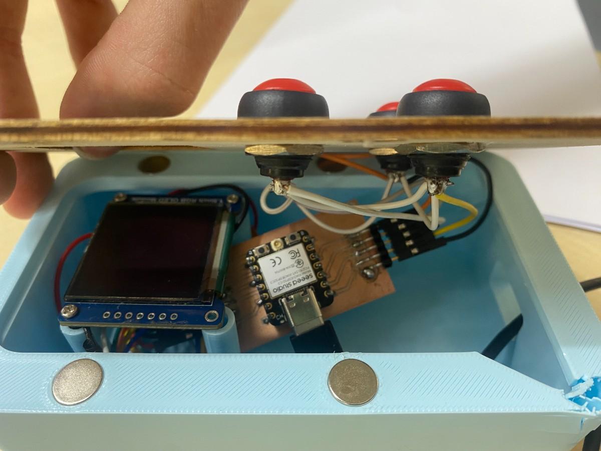
System Integration Tests
After assembling the device, I tested both the electronic and mechanical integration.
Electronics Working Test
In this test, the OLED displayed the interface and the buttons were tested while the electronics were inside the enclosure. This was important because electronics can work on the table but fail after being packaged if a cable is loose, the screen is misaligned, or the enclosure presses on a connection.
Wi-Fi and Full Game Test
I tested the two-device game flow by turning on both devices and allowing the second ESP32-C3 to connect to the host ESP32-C3.
The test checked that:
- the host device created the Wi-Fi network
- the player device connected to the host
- both devices showed the same quiz state
- both devices accepted button input
- the host calculated scores
- both devices showed the round result
- both devices showed the final winner
This test proved that the input, output, networking, and scoring systems were integrated into one working game.
Battery and Switch Test
I tested the device using the internal LiPo battery and the on/off slide switch.
The test checked that:
- the device turned on when the switch was moved to ON
- the device turned off when the switch was moved to OFF
- the OLED and ESP32-C3 powered correctly from the battery
- the device could run without a USB cable
- the wiring stayed connected inside the enclosure
Shake Tests
I performed shake tests to check whether the mechanical and electrical connections were stable. During the shake tests, I looked for:
- cover detachment
- loose magnets
- PCB movement
- screen movement
- button movement
- cable disconnection
- device reset
- OLED failure
- button failure
After the shake tests, the electronics continued to work. This showed that the magnetic cover, button mounting, PCB mounting, and internal wiring were reliable enough for normal handling.
Drop Test
I also performed a drop test from approximately 100 cm, around chest height.
The goal was to check whether the device could survive accidental handling mistakes. After the drop test, the electronics continued to work, and the device was still functional.
This was an important system integration test because it tested the enclosure, magnets, PCB mounting, OLED wiring, button wiring, and battery wiring together.
Assembly and Disassembly Tests
I tested opening and closing the enclosure multiple times. This confirmed that the magnets make the device serviceable and that the cover can be removed without damaging the wires.
Problems and Design Decisions
Cable Management
One of the biggest integration challenges was cable management. The cover holds the buttons, but the PCB is inside the base. Because the cover is removable, the cables need to be flexible enough to open the device, but they also need to fit inside the enclosure when it is closed.
I solved this by using crimped connectors and careful cable routing. The button wiring and OLED wiring are removable and more reliable than temporary jumper connections.
Shared Button Ground
Using a shared ground for the buttons reduced wiring complexity. Instead of sending four separate ground wires back to the PCB, I connected the button ground terminals together and routed one main ground line back to the PCB.
This made the wiring cleaner, but it also means the shared ground connection must be reliable. If the shared ground fails, multiple buttons could stop working.
OLED Mounting
The OLED is placed on an integrated 3D-printed stand. This helped align the display with the cover and avoided needing a separate mounting bracket.
The main challenge was making sure the screen height matched the cover opening. If the stand was too low, the screen would look recessed. If it was too high, the cover would press too much on the module.
PCB Mounting
The PCB is mounted with double-sided 3M mounting tape. This was fast, simple, and low-profile. It also avoided adding screw holes or standoffs.
For a future version, I would prefer to add a more formal PCB mounting system, such as printed standoffs, screws, or clips.
Battery Integration
The battery made the device portable, but it also added extra integration requirements. I needed to include a power switch, make sure the battery wiring was secure, and add a capacitor near the battery input.
The slide switch worked well because it allowed the device to be fully turned off when not in use.
Networking Timing
The two devices communicate wirelessly, but exact timing synchronization over Wi-Fi is not perfect. The current system is playable and demonstrates the concept, but future versions could improve synchronization.
What Worked Well
The system integration was successful because the device worked as a complete object, not just as separate parts.
The OLED was visible and aligned. The buttons were firmly mounted with nuts. The PCB fit inside the base. The LiPo battery powered the device. The slide switch turned the device on and off. The magnets made the enclosure removable. The crimped cables improved reliability. The two ESP32-C3 devices communicated wirelessly. The full game flow worked from question display to final winner screen.
Most importantly, the device passed shake and drop tests while continuing to function.
What I Would Improve
For the next version, I would improve:
- exact timing synchronization between the devices
- user experience and screen layout
- PCB mounting with screws or printed clips
- internal cable channels
- battery monitoring
- classroom-ready question editing
- support for more than two devices
- teacher dashboard
- sound or buzzer feedback
- larger or higher-resolution display
Final Reflection
This week helped me understand that system integration is not just about placing parts inside an enclosure. A project can work electronically but still fail as a system if the cables are loose, the screen is not aligned, the power path is unreliable, the cover does not close, or the device cannot survive handling.
In this version, I successfully integrated the PCB, OLED screen, four push buttons, LiPo battery, slide switch, 3D-printed base, laser-cut plywood cover, magnets, crimped wiring, and wireless ESP32-C3 communication into one working prototype.
The final result is a functional integrated version of Duello, a portable wireless quiz device that can be used by two students to play a competitive learning game.