Final Project - DESKO
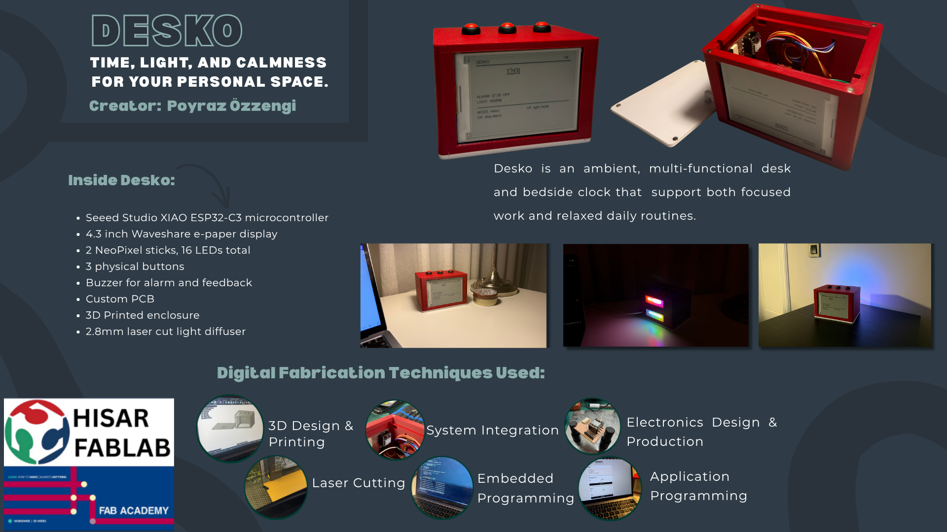
DESKO is an ambient desk and bedside clock that combines a time display, programmable lighting, alarm functions, a countdown timer, a stopwatch, physical controls, and a local browser interface in one custom-made object.
Poster
Final Project Video
Table of Contents
- Project Summary
- Presentation Slide and Video
- What Does It Do?
- Previous Work and Inspiration
- What I Designed
- System Diagram
- Main Systems
- Mechanical Design and Fabrication
- Electronics
- Embedded Programming
- Web Interface
- System Integration
- Bill of Materials
- Testing and Evaluation
- Problems and Fixes
- What Worked and What Did Not
- Implications and Future Development
- Files
- License
- Acknowledgements
Project Summary
DESKO is a multifunctional clock for a desk, study area, or bedside table. It uses an e-paper display for the main interface and NeoPixel LEDs for visual feedback. The clock can show time, set an alarm, create a warm wake-up light before the alarm, run a countdown timer, run a stopwatch, and create different ambient lighting modes.
The project is built around a Seeed Studio XIAO ESP32-C3. The ESP32-C3 controls the display, NeoPixels, buzzer, buttons, and web interface. The user can control DESKO in two ways:
- directly from the physical buttons on the device
- from a phone or computer through a local browser interface
Presentation Slide and Video
The final summary slide and final video are placed in the root of the website repository also at the end of this decumentation.
What Does It Do?
DESKO is a physical clock with lighting and productivity features.
The main functions are:
| Function | Description |
|---|---|
| Clock | Shows the current time on the e-paper display |
| Set time | Allows the software clock time to be adjusted |
| Alarm | Stores an alarm time and triggers sound and light |
| Wake-up light | Slowly increases warm light before the alarm |
| Ambient light | Provides selectable NeoPixel lighting modes |
| Countdown | Counts down from a selected duration |
| Countdown LED feedback | Changes the NeoPixels as the countdown progresses |
| Stopwatch | Tracks elapsed time |
| Buzzer feedback | Gives sound feedback for alarm and countdown |
| Physical controls | Uses buttons to move through menus and change values |
| Web interface | Lets the user control DESKO from a browser |
The wake-up feature is one of the main parts of the project. When the alarm is enabled, the NeoPixels begin a gradual warm light effect before the alarm time. This makes the clock more than a simple buzzer alarm. The light gives a visual transition before the sound starts.
The countdown feature also uses light as information. During the countdown, the LEDs visually show the passage of time. This makes the timer easier to understand from a distance without constantly looking at the screen.
Previous Work and Inspiration
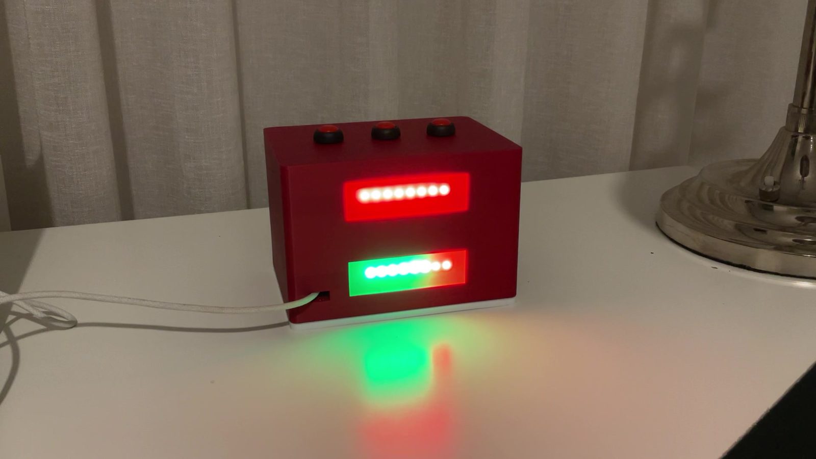
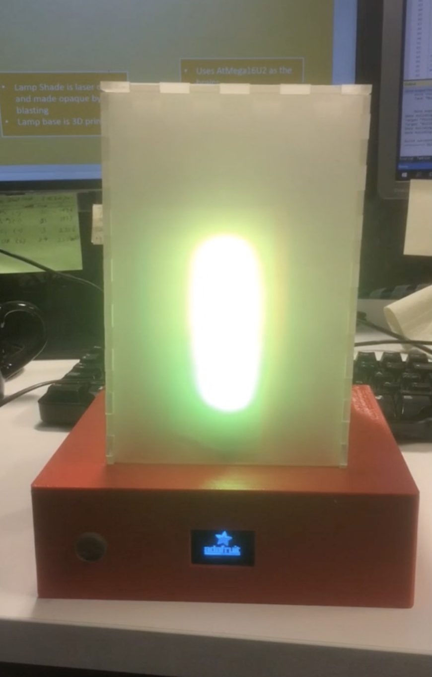
At the beginning of the project, I wanted to combine RGB light with everyday life. I looked at previous Fab Academy projects and found Alok Sethi’s 2019 Oulu FabLab project, a wake-up alarm lamp. That project used light as part of an alarm routine, which was close to the direction I wanted to explore.
DESKO is also related to existing alarm clocks, wake-up lights, smart clocks, Pomodoro timers, and desk lamps. However, I did not want to copy a commercial product. My aim was to make my own integrated clock prototype using the skills from Fab Academy.
Compared with a normal alarm clock, DESKO combines:
- a clock interface
- ambient lighting
- wake-up light behavior
- countdown and stopwatch tools
- a local browser control panel
- a custom fabricated enclosure
- embedded programming and system integration
The main difference is that the project is not just a bought clock placed in a box. I designed the physical form, assembled the electronics, wrote the code, created the web interface, and integrated the parts into one object.
What I Designed
I designed the main physical and digital parts of DESKO.
The designed parts include:
| Designed part | Purpose |
|---|---|
| Enclosure layout | Holds the display, buttons, LEDs, buzzer, controller, and wiring |
| Display opening | Positions the e-paper screen on the front face |
| Button placement | Makes the physical controls accessible from the top |
| Internal layout | Organizes the electronics and wires inside the body |
| NeoPixel placement | Allows the LEDs to act as ambient and feedback lighting |
| Magnetic / removable access | Makes the inside easier to open for debugging |
| E-paper UI | Shows the clock, menu screens, alarm, countdown, and stopwatch |
| Button menu system | Allows local control without a computer |
| Web interface | Allows control from a phone or computer |
| Final integrated code | Combines all functions in one program |
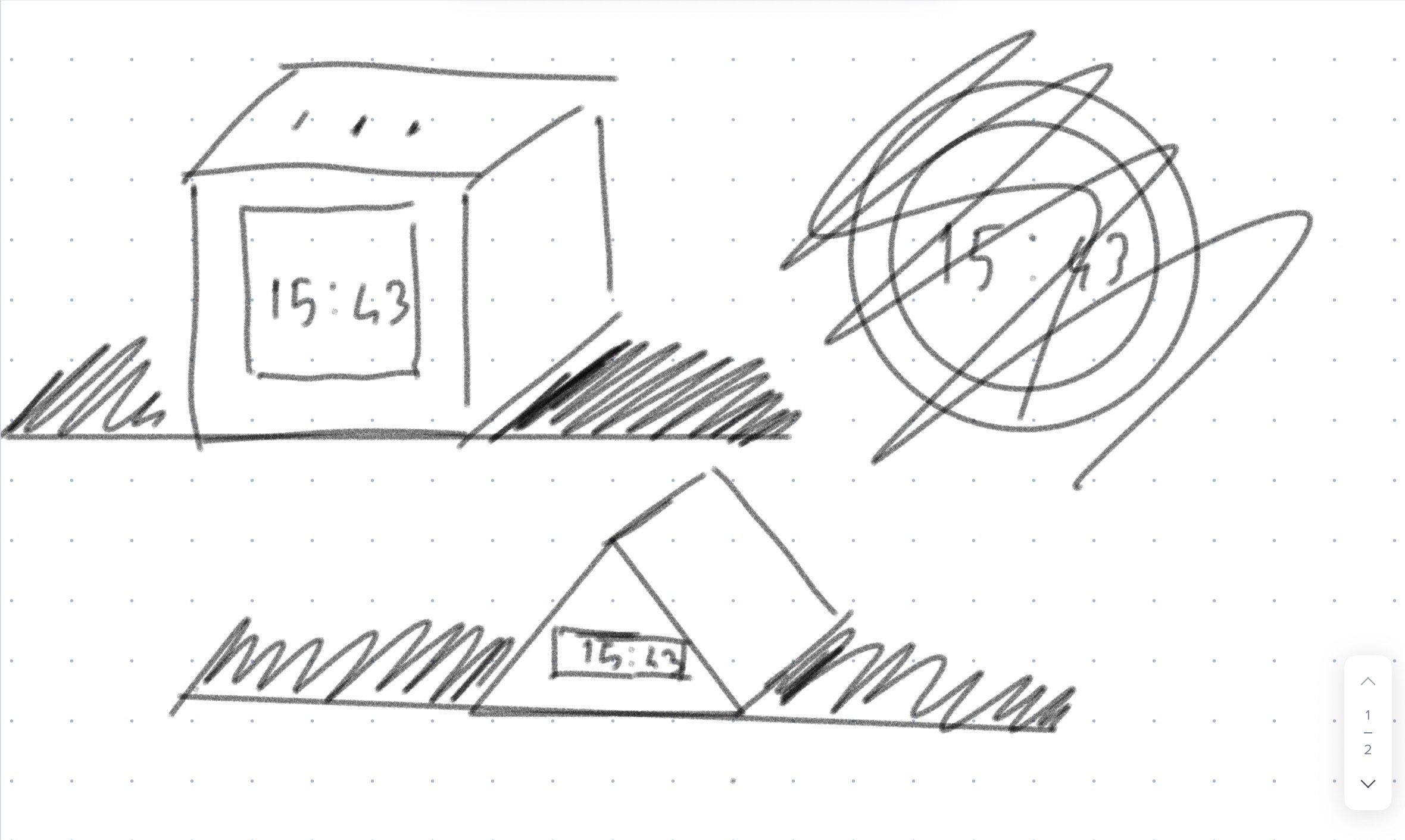
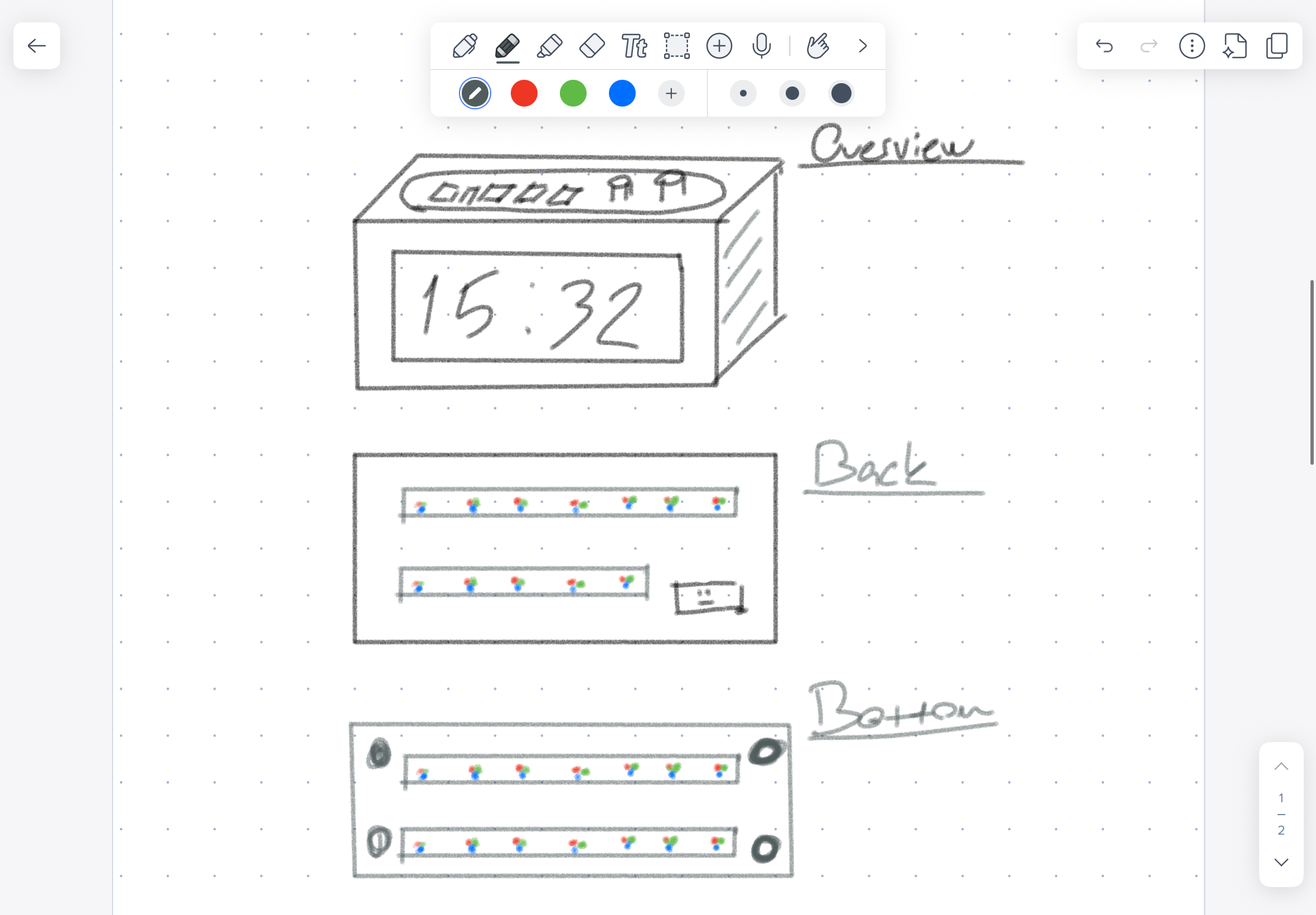
Early sketches explored different shapes, including a triangular version and a round version. I chose a rectangular prism because it was cleaner, easier to fabricate, and better for organizing the internal components.
System Diagram
The final system can be understood as a single controller connected to input, output, interface, and power systems.
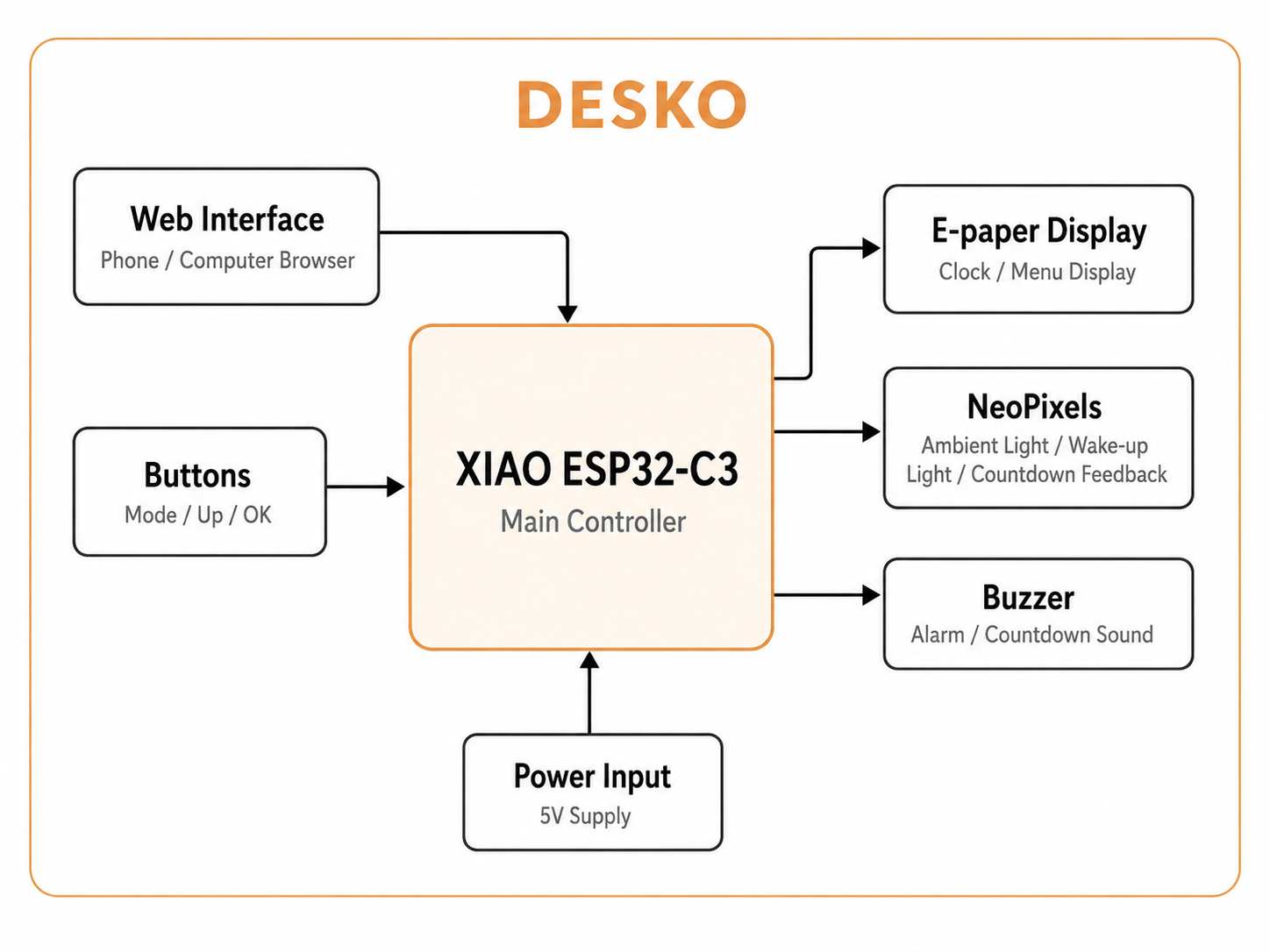
Diagram visualized by ChatGPT
                  Physical buttons
                         |
                         v
Phone / Computer -> ESP32-C3 controller -> E-paper display
   Web browser          |                  Clock and menus
   192.168.4.1          |
                        |-> NeoPixel LEDs
                        |   Ambient light, wake-up light, countdown feedback
                        |
                        |-> Buzzer
                        |   Alarm and timer sound
                        |
                        |-> 5V power input
                        |
                        v
                  Custom enclosure
The physical buttons and the browser interface control the same functions. This was important because I wanted DESKO to be usable as a normal physical object, but also easier to configure through a browser when needed.
Main Systems
DESKO is made from several connected systems.
| System | Role |
|---|---|
| Microcontroller system | Runs the full program on the ESP32-C3 |
| Display system | Shows time, screen titles, settings, and hints |
| Lighting system | Controls NeoPixel ambient modes and visual feedback |
| Alarm system | Stores alarm time and triggers buzzer and wake-up light |
| Countdown system | Tracks remaining time and updates the LEDs |
| Stopwatch system | Tracks elapsed time |
| Button system | Provides local interaction |
| Web interface system | Provides browser-based control |
| Power system | Supplies the ESP32-C3, display, LEDs, and buzzer |
| Enclosure system | Holds and protects all parts |
The main challenge was avoiding conflicts between systems. For example, the ambient light mode should run normally, but the alarm and countdown need to override it when they are active.
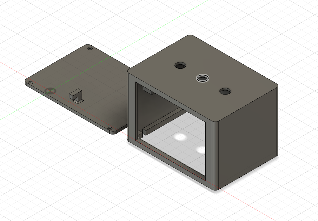
Mechanical Design and Fabrication
Enclosure Design
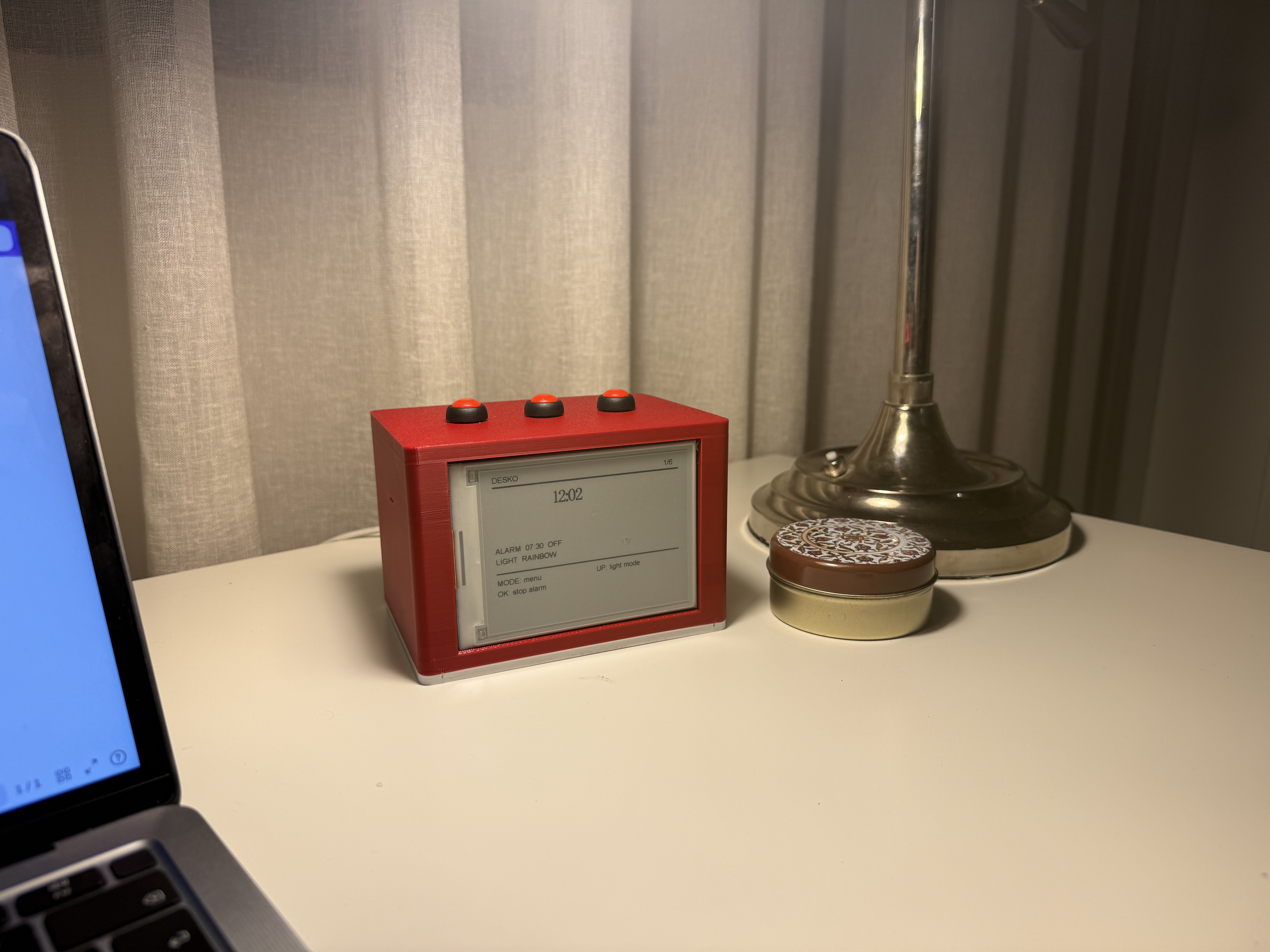
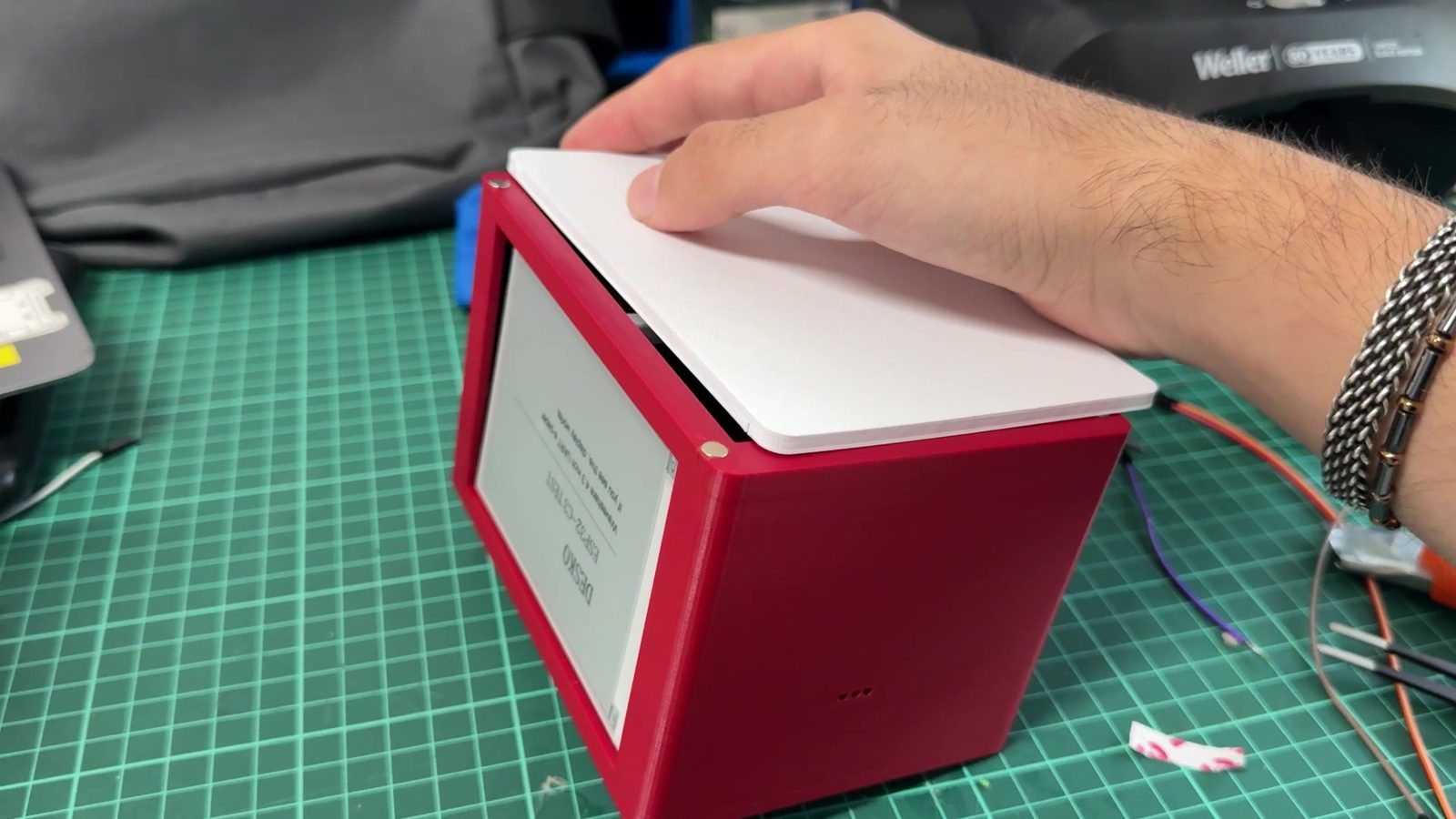
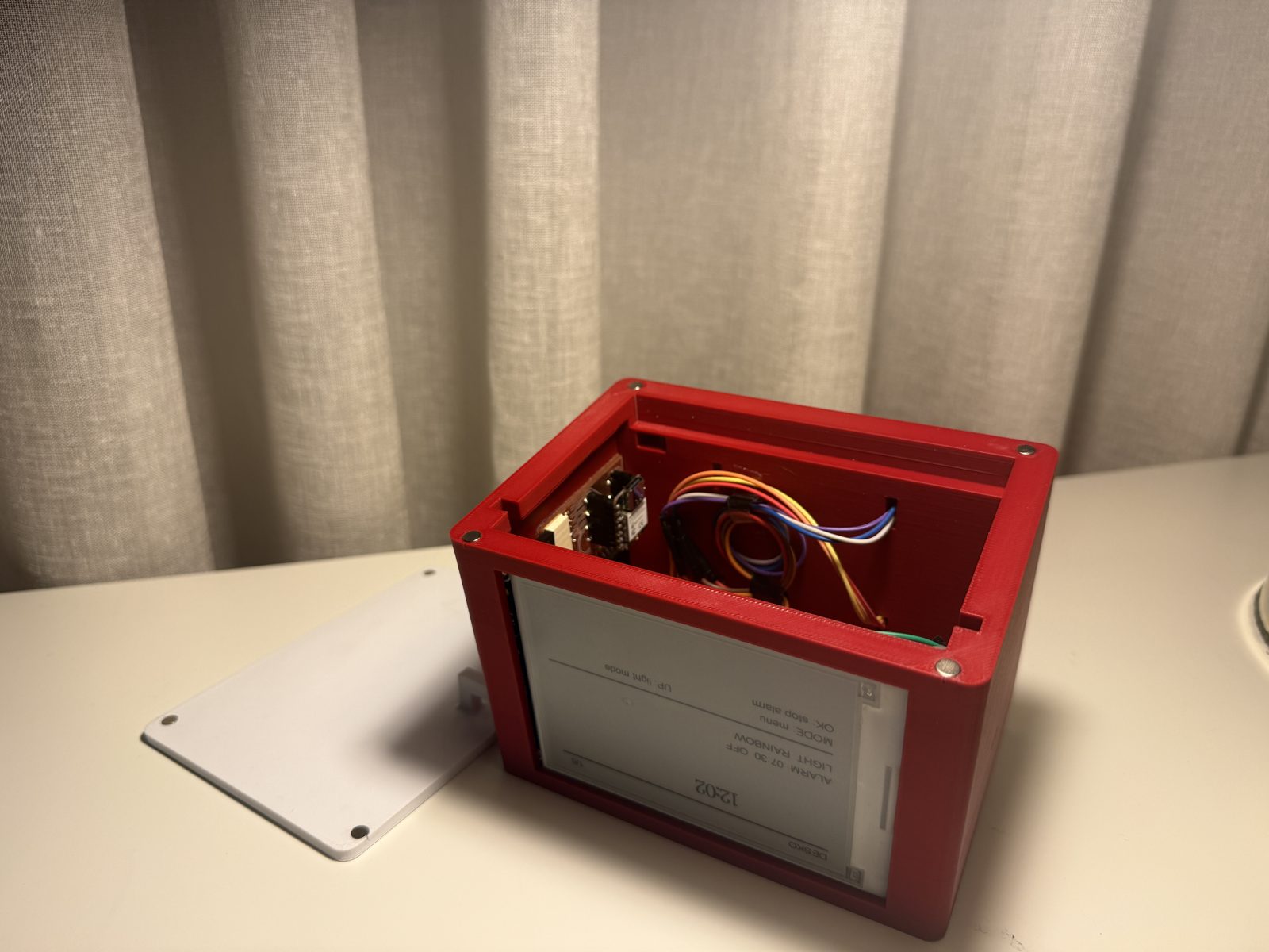
The enclosure was designed around the largest and most visible component, the e-paper display. The display is placed on the front face so the time and menu screens are easy to read. The buttons are placed on the top so the user can change screens, adjust values, and stop alarms without opening the device.
The enclosure also needed space for:
- ESP32-C3 controller
- e-paper display wiring
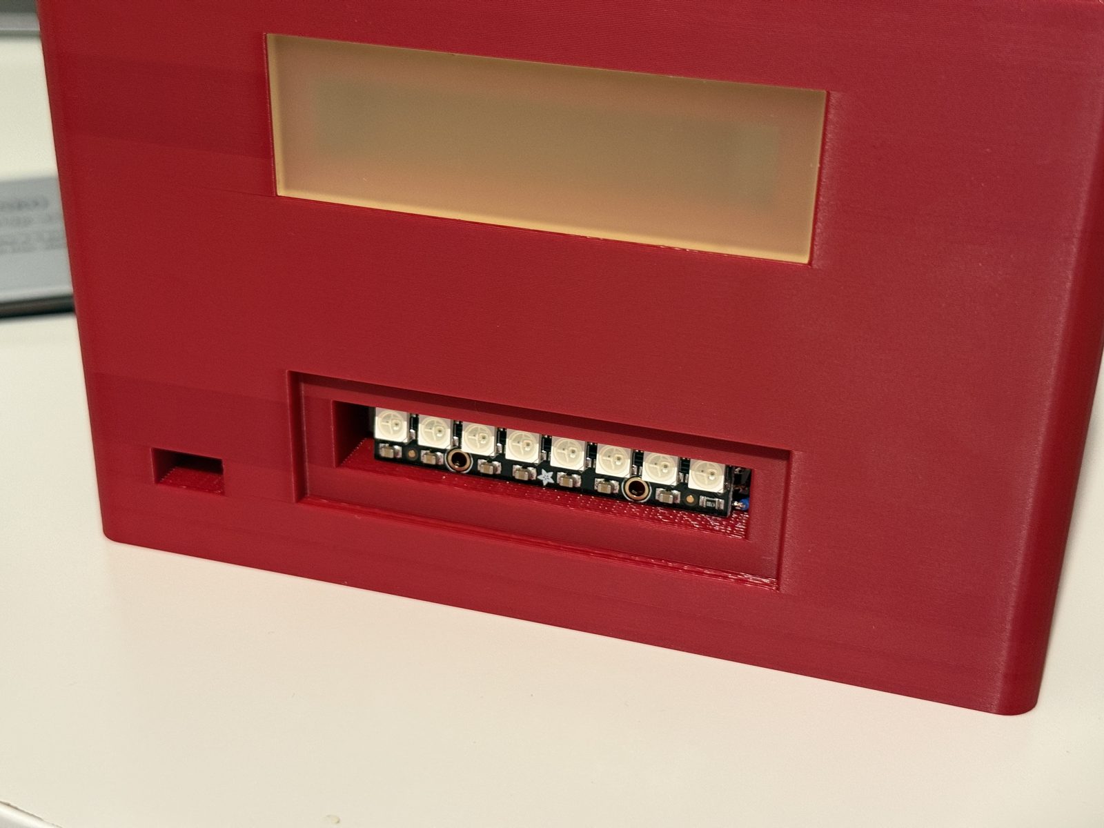
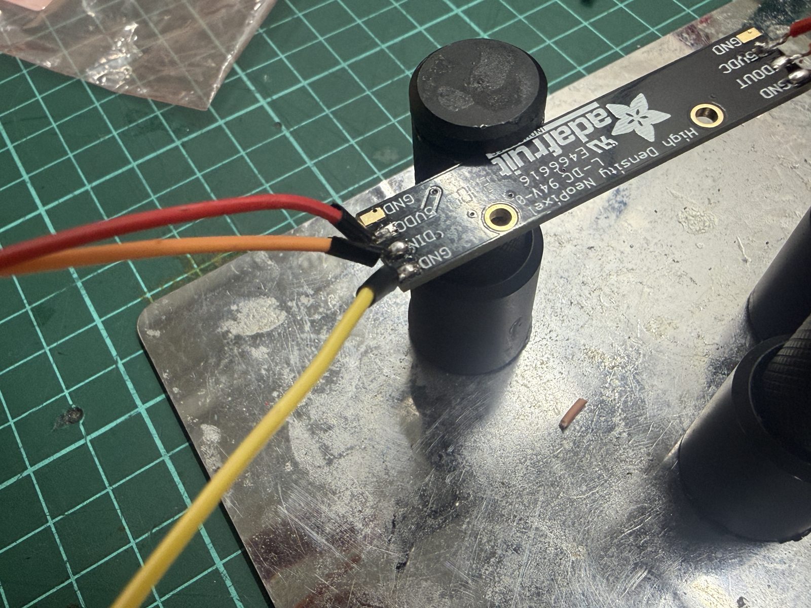
- two NeoPixel sticks
- buzzer
- physical buttons
- internal wires
- power input
- removable or magnetic access for debugging
3D Design
The main enclosure geometry was developed digitally before fabrication. The model was used to check the proportions, display placement, button placement, and internal space.
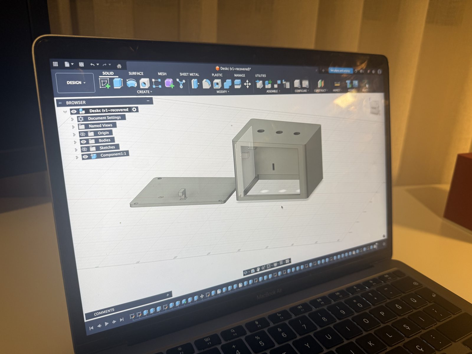
The 3D design stage helped me think about:
- how the user sees the clock from the front
- how the buttons are reached from the top
- how much space the electronics need inside
- how the back or bottom can be opened for maintenance
- where the LEDs should be placed for visible light effects
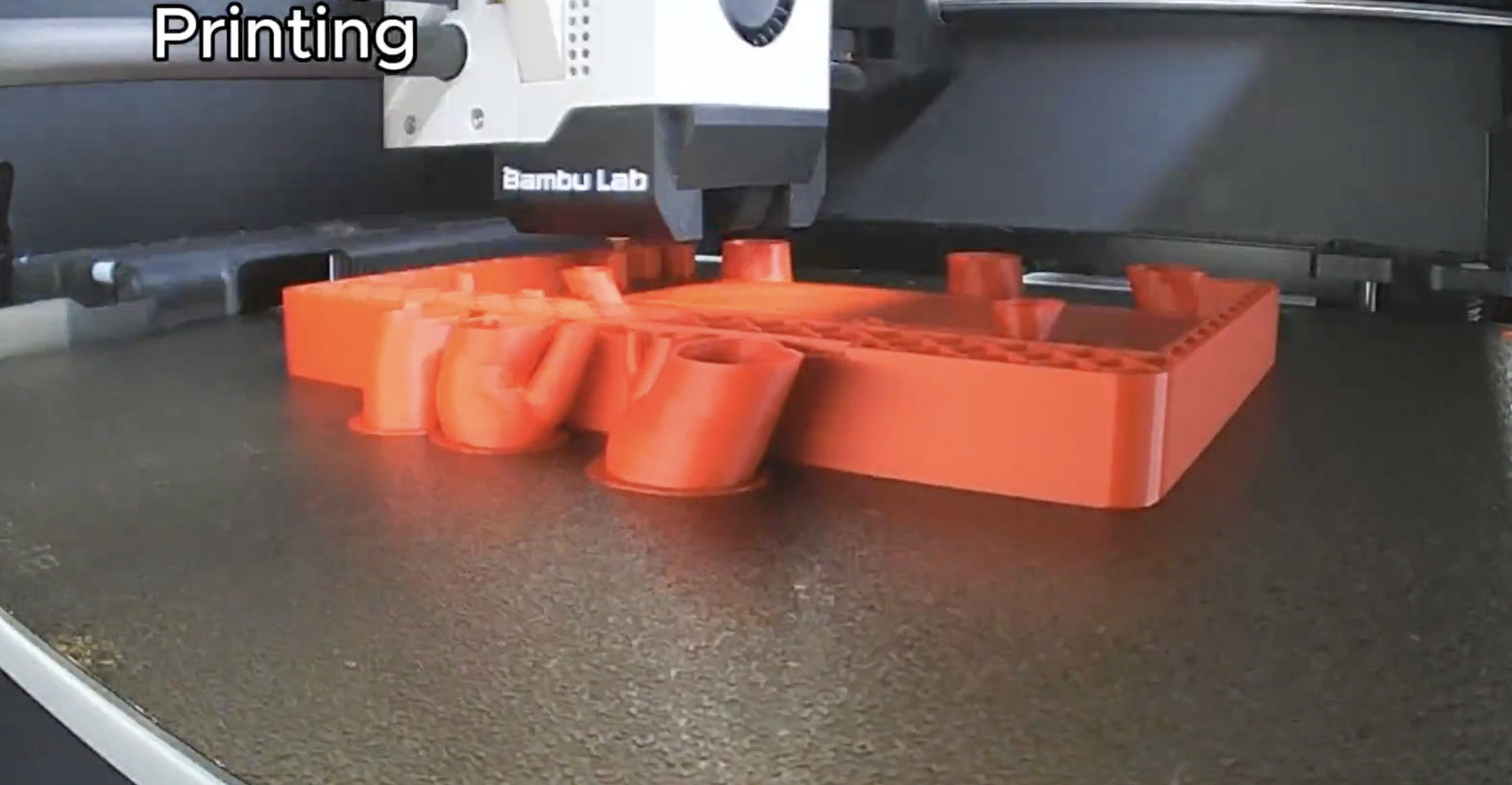
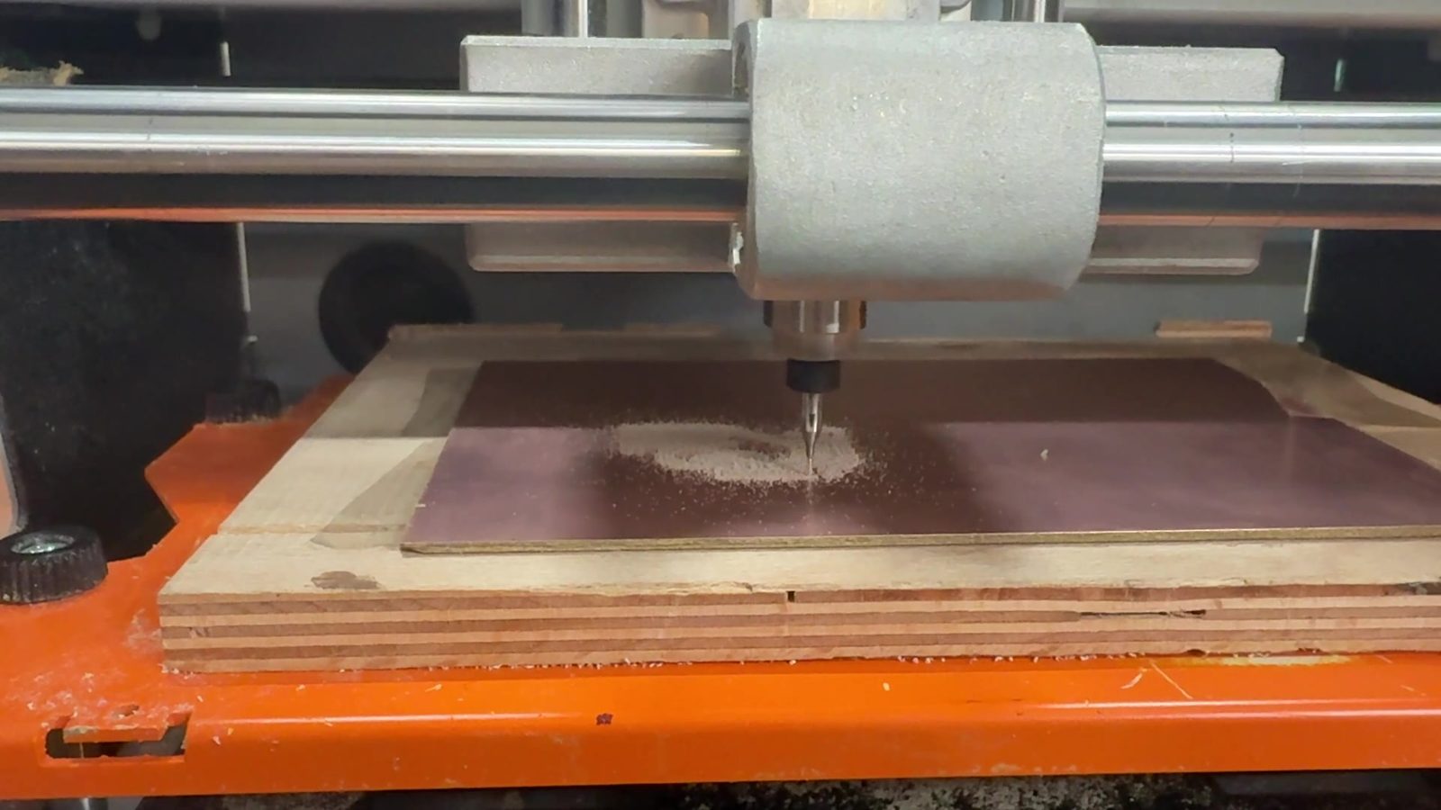
3D Printing
3D printing was used for the custom body parts of DESKO. This was useful because the shape had to match my specific components, not a standard commercial box. The 3D printed part gave the project its main physical form and made it possible to place the electronics inside one object.
Laser Cutting
Laser cutting was used for flat parts which are the light diffusers ont the back of DESKO. Flat laser-cut parts are useful because they can be produced quickly and accurately. I used a semi transparent acrylic and laser cut with our XTool laser that I used in the previous weeks.
Assembly
During assembly, the main focus was packaging. I wanted the final device to look like a finished object from the outside, while keeping the inside accessible enough for debugging.
The packaging methods were:
| Component | Packaging method |
|---|---|
| E-paper display | Mounted behind the front opening |
| Buttons | Fixed through top holes |
| NeoPixels | Placed inside the enclosure for light effects |
| ESP32-C3 | Mounted inside with access to wiring |
| Buzzer | Placed inside but not fully sealed |
| Wires | Routed inside the enclosure |
| Power cable | Routed from the back |
Electronics
Main Controller
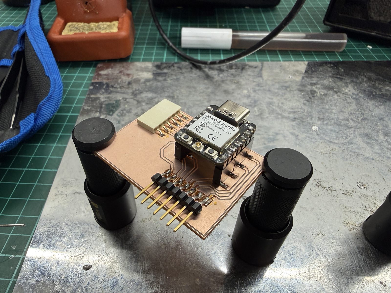
DESKO uses a Seeed Studio XIAO ESP32-C3 as the main controller. I chose it because it is small, supports Wi-Fi, can be programmed with Arduino IDE, and has enough GPIO capability for this prototype.
The ESP32-C3 controls:
- e-paper display
- NeoPixel LEDs
- buttons
- buzzer
- web server
- software clock
- alarm logic
- countdown logic
- stopwatch logic
Inputs
The main physical inputs are the buttons on the top of the clock.
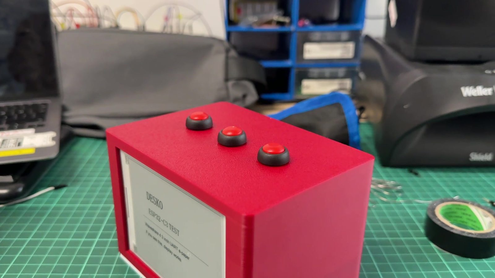
The button interface uses three main control buttons:
| Button | Function |
|---|---|
| MODE | Move between screens |
| UP | Change values or cycle light modes |
| OK | Select fields, toggle options, or stop alarm |
This kept the physical interface simple. Instead of adding many separate buttons, I used a small menu system with only a few controls.
Outputs
The main output devices are:
| Output | Purpose |
|---|---|
| E-paper display | Shows time, menu screens, settings, and hints |
| NeoPixels | Creates ambient light and visual timer feedback |
| Buzzer | Makes sound for alarm and countdown completion |
The e-paper display is used because it gives a clean clock-like visual style. The NeoPixels make the project more interactive by turning light into information. The buzzer gives clear feedback when an alarm or timer ends.
Power
The project uses a 5V USB-C power supply. All electronic modules share a common ground.
The power system was kept simple for the prototype. A future version could improve this with a battery, charging circuit, protection, and a more finished power board.
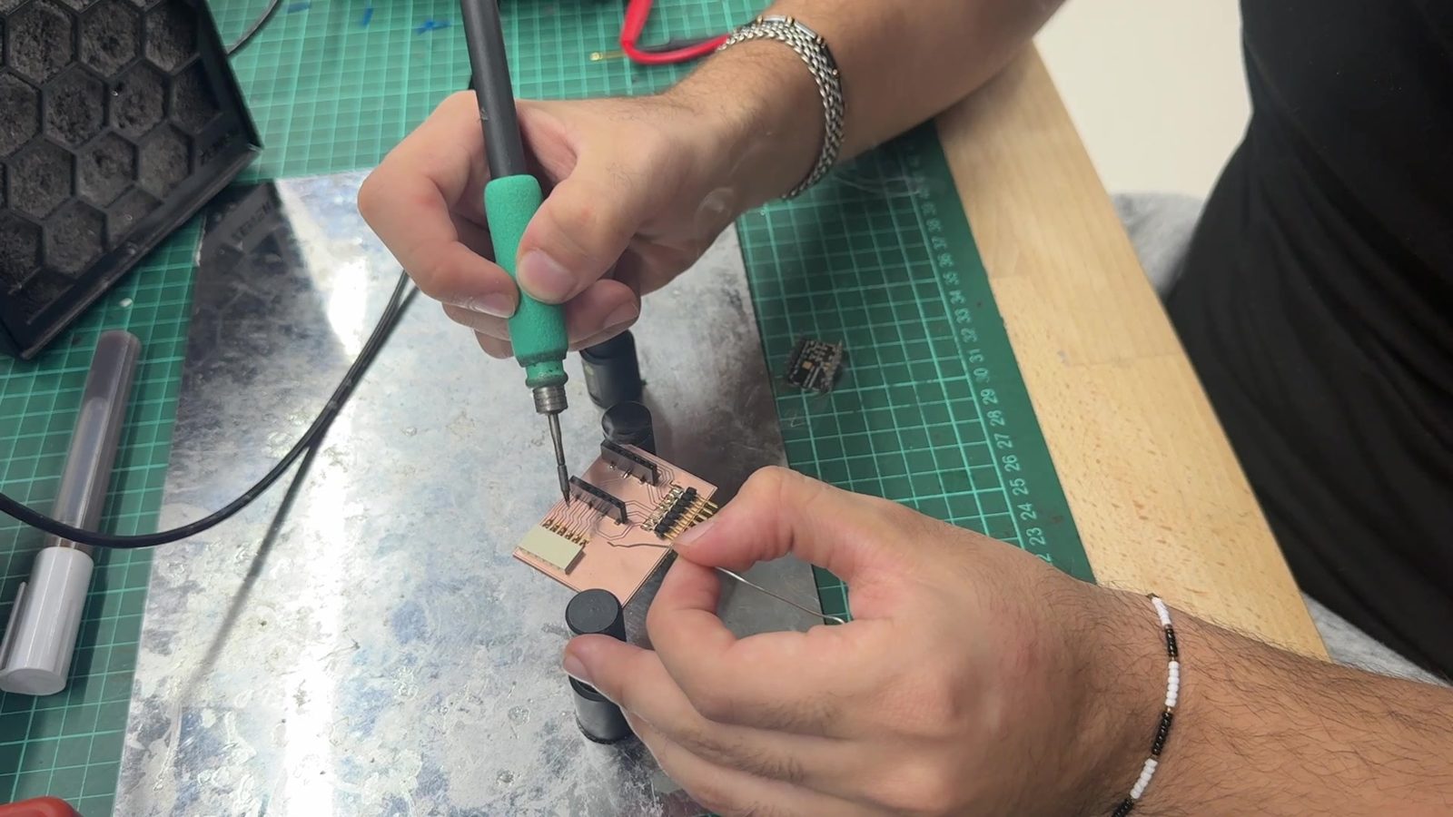
PCB and Electronics Production Connection
During the electronics design and electronics production weeks, I designed and milled ESP32-C3 based boards and tested input and output devices. These weeks helped me understand routing, ground strategy, soldering, continuity testing, and debugging.
For the final prototype, the main focus was integrating the controller, display, LEDs, buttons, and buzzer inside DESKO. The final wiring is still more prototype-like than a commercial product, but the earlier PCB work helped me understand how the final electronics should be organized.
A future revision should combine more of the wiring into a custom final PCB. That would make the inside cleaner, easier to assemble, and more reliable.
Embedded Programming
The final code combines several systems into one ESP32-C3 program.
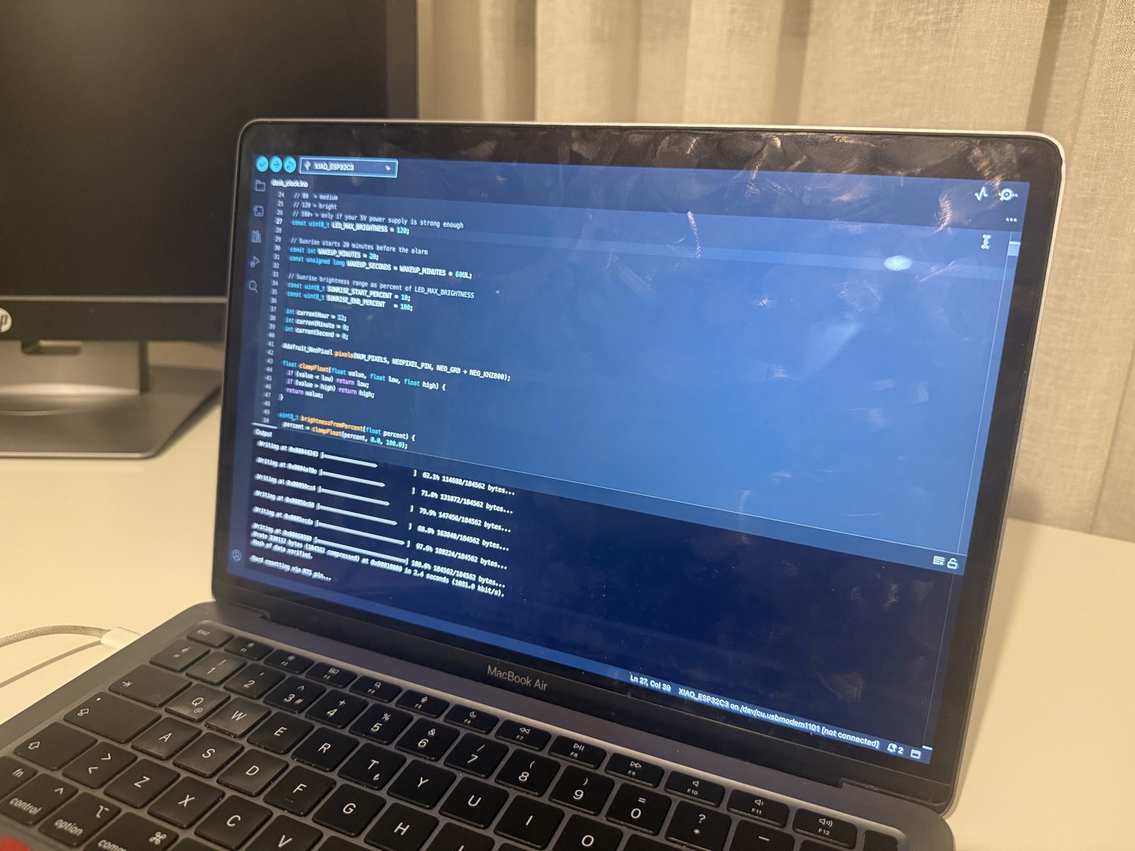
The software also includes browser control panel.
The code is organized so the main loop repeatedly checks the web server, updates time, reads buttons, handles alarm/countdown/stopwatch behavior, updates lighting, and refreshes the display only when needed.
void loop() {
  server.handleClient();

  updateSoftwareClock();

  if (btnMode.pressed()) handleModeButton();
  if (btnUp.pressed())   handleUpButton();
  if (btnOk.pressed())   handleOkButton();

  handleMinuteDisplayUpdate();
  handleAlarm();
  handleCountdown();
  handleStopwatchDisplay();
  applyAmbientLighting();

  if (displayDirty) updateDisplay();
}
This structure was important because all parts need to work together. If the code stayed as separate test programs, DESKO would not function as a final integrated project.
E-paper Display Screens
The display interface has six main screens:
| Screen | Purpose |
|---|---|
| 1/6 Home | Shows time, alarm status, and light mode |
| 2/6 Set Time | Allows hour and minute adjustment |
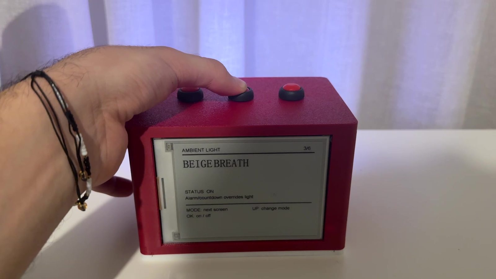
| 3/6 Ambient Light | Shows and changes the selected light mode |
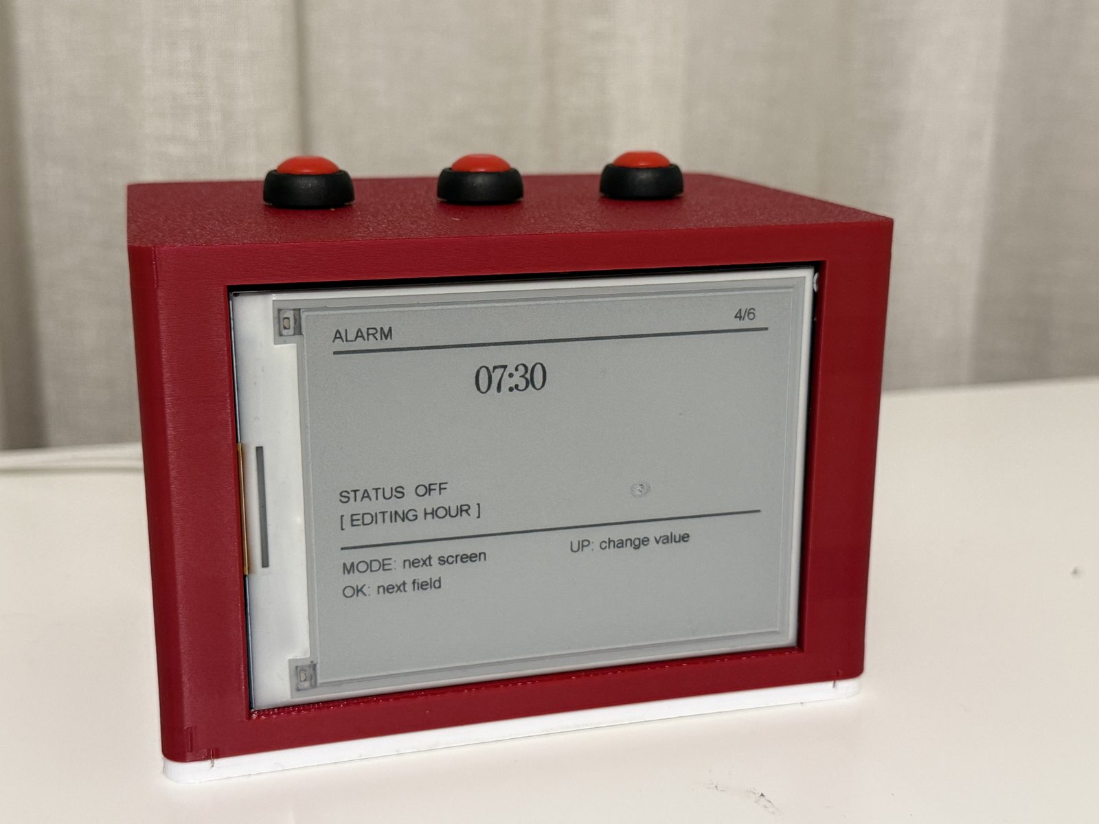
| 4/6 Alarm | Sets alarm hour, minute, and ON/OFF |
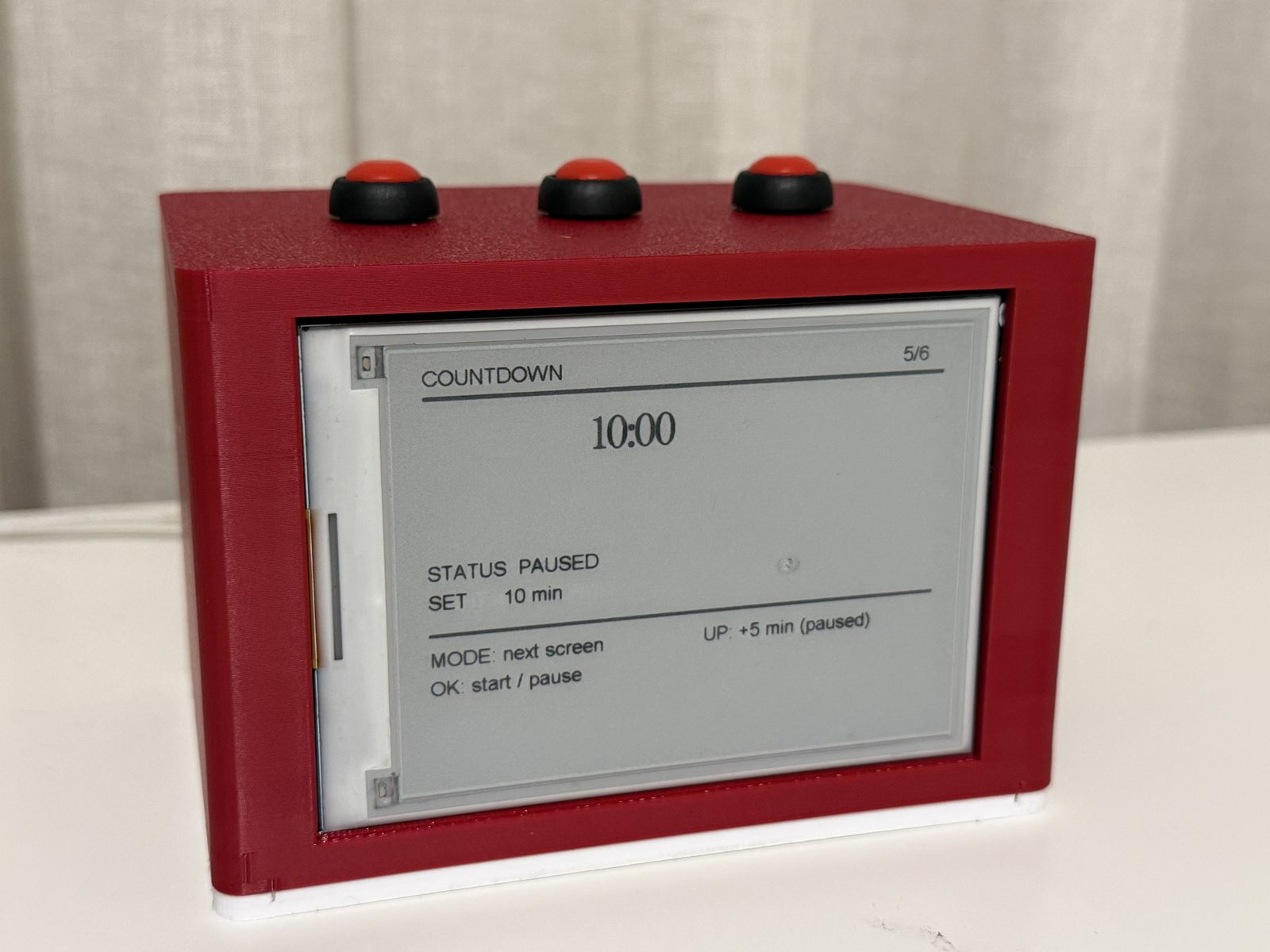
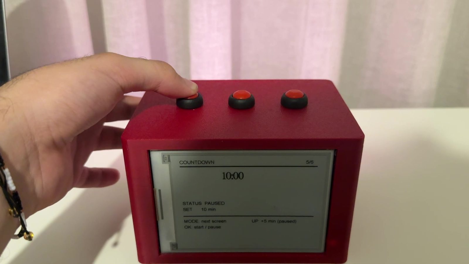
| 5/6 Countdown | Sets and controls countdown |
| 6/6 Stopwatch | Starts, pauses, and resets stopwatch |
Each screen includes short hints at the bottom. This was necessary because the same three buttons do different things depending on the active screen.
Display Refresh Strategy
The e-paper display refreshes more slowly than a normal OLED or LCD. Because of that, I did not want the display to refresh constantly. I used a displayDirty flag so the screen only updates when something important changes.
This improved the user experience and reduced unnecessary refreshes.
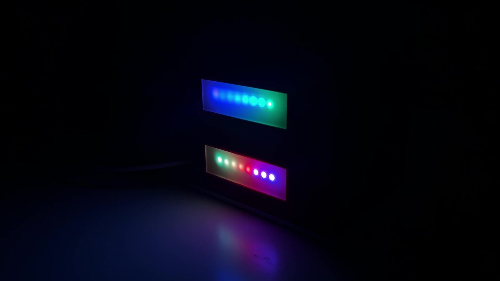
Ambient Light Modes
The NeoPixel system includes several modes:
| Mode | Description |
|---|---|
| OFF | Turns the LEDs off |
| WARM | Warm steady light |
| BEIGE BREATH | Slowly rising and falling beige light |
| BLUE NIGHT | Dim blue night light |
| RAINBOW | Animated color effect |
| FOCUS WHITE | Bright warm white light |
The maximum brightness can be controlled from the code so the LEDs do not become too intense.
Alarm and Wake-up Light
The alarm has two parts:
- A warm light sequence before the alarm
- A buzzer and brighter light at the alarm time
The wake-up light starts before the alarm and slowly increases. In the final code, this behavior is designed for a 20-minute wake-up period. The important point is that the wake-up light can turn on even if the ambient lighting is currently off.
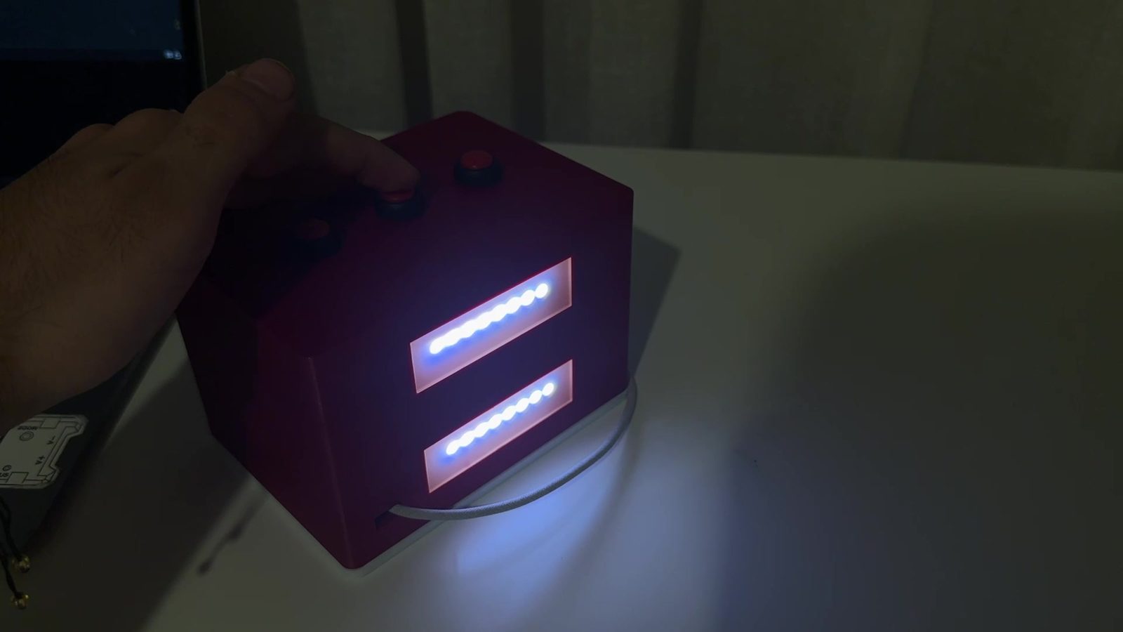
Countdown LED Feedback
The countdown timer uses the LEDs as a progress indicator. As time passes, the LEDs gradually shift to show that the timer is running out. When the countdown finishes, the buzzer rings and the LEDs turn into a clear alert color.
Stopwatch
The stopwatch tracks elapsed time and can be controlled from the clock interface. Because the e-paper does not need to update every second, the display refresh is controlled to avoid unnecessary screen updates.
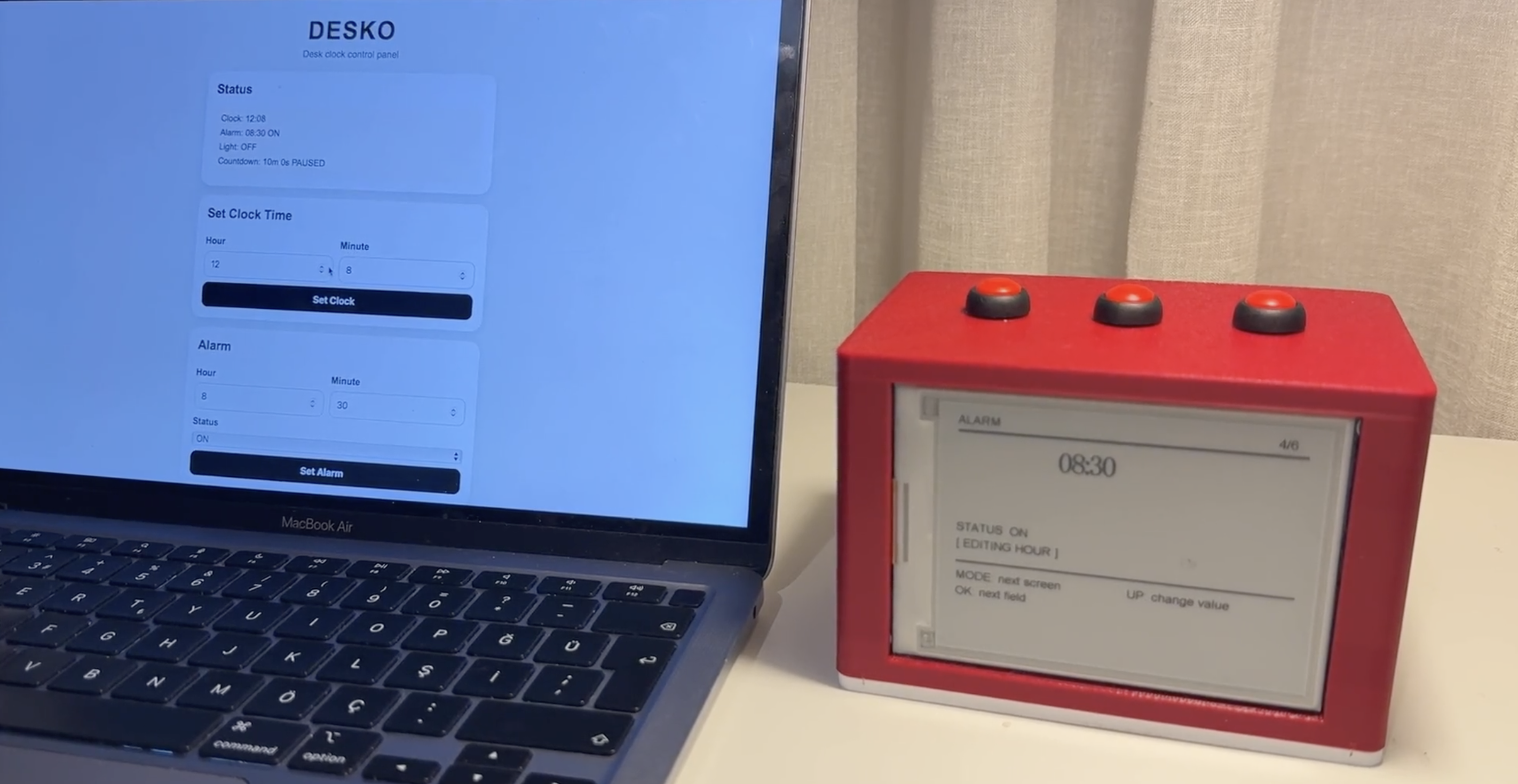
Web Interface
The web interface allows the user to control DESKO from a phone, tablet, or computer.
The ESP32-C3 creates its own Wi-Fi network:
const char* WIFI_SSID = "DESKO_Control";
const char* WIFI_PASSWORD = "12345678";
After connecting to this network, the user opens:
http://192.168.4.1
The browser page then shows the DESKO control panel.
The web interface includes:
| Section | Function |
|---|---|
| Status | Shows clock time, alarm status, light mode, and countdown |
| Set Clock Time | Changes the software clock |
| Alarm | Sets alarm hour, minute, and ON/OFF |
| Ambient Light | Changes the NeoPixel mode |
| Countdown | Sets, starts, pauses, and resets the countdown |
| Quick Controls | Stops the buzzer or turns LEDs off |
The web interface uses routes such as:
server.on("/", handleWebPage);
server.on("/setTime", handleSetTimeWeb);
server.on("/setAlarm", handleSetAlarmWeb);
server.on("/ambient", handleAmbientWeb);
server.on("/countdown", handleCountdownWeb);
server.on("/countdownToggle", handleCountdownToggleWeb);
server.on("/countdownReset", handleCountdownResetWeb);
server.on("/stopAlarm", handleStopAlarmWeb);
server.on("/ledOff", handleLedOffWeb);
This made DESKO easier to demonstrate and use because the user does not have to do every setting from the physical buttons.
System Integration
System integration was the most important part of the final project.
Before final integration, I had tested many parts separately:
- buttons
- buzzer
- NeoPixels
- display
- web interface
- alarm logic
- countdown logic
- stopwatch logic
The final project required all of these to work together in the same object.
Integration Goals
The integration goals were:
- the device should look like one finished clock, not separate modules
- the display, buttons, LEDs, buzzer, and web interface should run from one codebase
- the internal wiring should fit inside the enclosure
- the physical buttons and web interface should control the same state variables
- alarm and countdown functions should override ambient lighting when needed
- the e-paper display should refresh only when needed
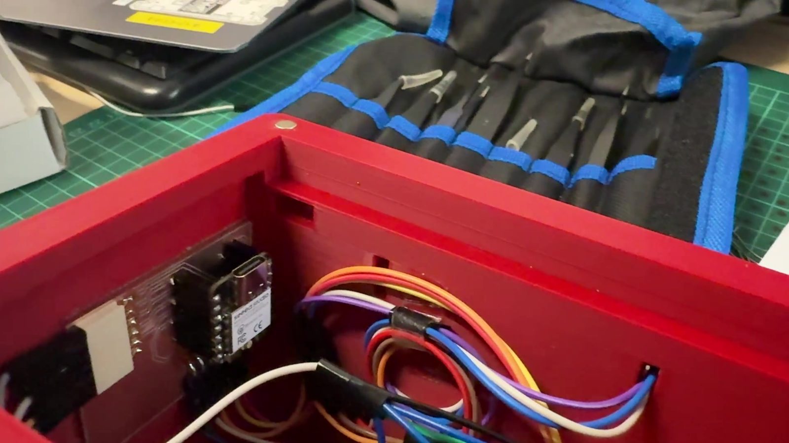
Physical Integration
The physical parts were integrated by placing the display on the front, buttons on the top, lighting inside or behind the body, and electronics inside the enclosure. The enclosure hides the electronics during normal use but still allows access for debugging.
Electronic Integration
The electronics were connected around the ESP32-C3 PCB board. The main integration rule was that all parts share a common ground. This is especially important for the NeoPixels, buzzer, and display communication.
The wiring was planned so each component had a clear role:
| Component | Connection type |
|---|---|
| Buttons | Digital inputs |
| Buzzer | Digital output |
| NeoPixels | Single data line output |
| E-paper display | Display communication |
| Web interface | ESP32-C3 Wi-Fi |
| Power | 5V and common ground |
Software Integration
The software integration was more difficult than writing separate test codes. The program needed to decide which function has priority.
The priority logic is:
- Alarm ringing and countdown finished states have highest priority
- Wake-up light overrides normal ambient mode
- Countdown LED feedback overrides ambient mode while active
- Ambient mode runs when no higher-priority function is active
- Display refresh only happens when
displayDirtyis true
This prevented different light functions from fighting each other.
After a draft of the complete software done by myself with the seperate test codes for component testing, I rewrote the code with the help of AI, Claude, to have a cleaner and more efficient working code as it does the UI better.
Bill of Materials
The exact cost depends on which parts are already available in the lab. This is an approximate bill of materials for the final prototype.
| Item | Purpose | Estimated Cost |
|---|---|---|
| Seeed Studio XIAO ESP32-C3 | Main controller | $6 |
| E-paper display | Main clock and menu display | $35-45 |
| NeoPixel LED sticks 8 | Ambient light and timer feedback | $8-12 |
| Buzzer | Alarm and countdown sound | $1 |
| Push buttons | Physical controls | $1-2 |
| Wires and connectors | Internal wiring | $3 |
| 5V USB-C power supply | Power | $5-8 |
| 3D printing filament | Enclosure/body/mounts | $3-5 |
| Laser cut material | Panels/diffuser/structure | $5-10 |
| Magnets, screws, tape, small hardware | Assembly | $4 |
Estimated total cost:
Approximately $70-95
The cost is given as an estimate rather than an exact number because taxes and customs regulations in Turkey rapidly change over time, the final cost can be slightly different from the values listed here.
The e-paper display is the most expensive component. A cheaper future version could use a smaller display or a different screen type, but the e-paper screen gives DESKO a clean clock-like look.
Testing and Evaluation
I evaluated DESKO by checking whether the full system worked as one device, not just as separate tests before putting everything together i ran a final check of the components.
![]()
Test Checklist
| Test | Result |
|---|---|
| ESP32-C3 uploads and runs code | Worked |
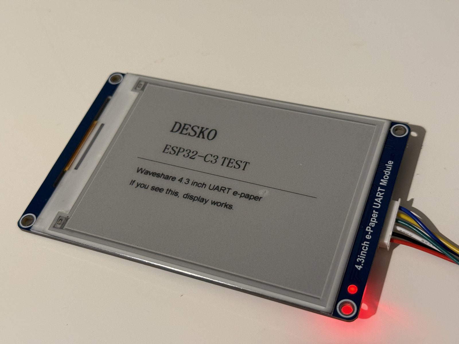
| E-paper display shows the interface | Worked |
| Home screen shows clock time | Worked |
| Physical buttons navigate screens | Worked |
| Time setting can be changed | Worked |
| Ambient modes change LEDs | Worked |
| Alarm can be set | Worked |
| Wake-up light starts before alarm | Worked in testing |
| Buzzer rings for alarm | Worked |
| Countdown can be set and started | Worked |
| Countdown LEDs show progress | Worked |
| Stopwatch runs | Worked |
| Web interface creates local Wi-Fi | Worked |
| Browser opens the control panel | Worked |
| Web interface changes settings | Worked |
| Enclosure holds the parts | Worked, but could be improved |
| Internal wiring fits | Worked, but could be improved |
Evaluation Criteria
The project is successful if:
- it shows the time clearly
- the buttons can control the interface
- the web interface can control the same main functions
- the alarm and countdown work reliably
- the NeoPixels give useful light feedback
- the buzzer gives clear sound feedback
- the device fits inside its enclosure
- the final video can demonstrate the main functions clearly
Problems and Fixes
| Problem | Fix |
|---|---|
| Too many separate test codes | Combined the functions into one main program |
| E-paper refresh was slow | Used displayDirty so the display only refreshes when needed |
| LED modes could conflict | Gave alarm and countdown priority over ambient lighting |
| Button interface could be confusing | Added screen numbers and on-screen hints |
| Web interface needed to work without a router | Made the ESP32-C3 create its own Wi-Fi access point |
| Countdown needed better visual feedback | Used NeoPixels to show countdown progress |
| Alarm needed more than just sound | Added gradual warm wake-up light |
| Internal wiring could become messy | Planned the enclosure around component placement and cable routing |
| Project risked becoming too feature-heavy | Focused on stabilizing the main features instead of adding new ones |
What Worked and What Did Not
What Worked
The main functions worked together in the final code. The e-paper display shows the clock interface and menu screens. The physical buttons can move through the interface. The NeoPixels produce ambient lighting and timer feedback. The buzzer gives alarm and countdown feedback. The local web interface can control important settings from a browser.
The web interface was especially useful because setting time, alarm, and countdown values is easier from a phone or computer than from only three physical buttons.
The system integration also worked well enough to demonstrate the final project as a single device.
What Did Not Work Perfectly
The final prototype still has areas that could be improved.
The e-paper screen is slower than a normal display, so it is not ideal for fast animations or second-by-second updates. The wiring works, but a future version should use a more integrated PCB and cleaner connectors. The web interface works, but it could be made more polished visually. The power system is fine for a prototype, but a final product would need a safer and more complete power design.
The biggest lesson was that finishing the project was not about adding more features. It was about making the existing features reliable and understandable.
Implications and Future Development
DESKO currently makes the most sense as an open-source educational prototype. It shows how a student can combine digital fabrication, electronics, embedded programming, interface design, and system integration into one object.
Future improvements could include:
- a rtc module for more accurate timekeeping
- cleaner internal wiring
- better power management
- rechargeable battery option
- improved enclosure tolerances
- more polished e-paper graphics
- improved web interface design
- saved settings using non-volatile memory
If the design becomes even more reliable, this could be sold to customers as well.
Files
Final project file links:
- Final summary slide
- Final project video
- Final project design files
- Final project design pcb files
- Final project design code files
Related Weekly Documentation
These weeks contributed directly to the final project:
- Week 02 - Computer-Aided Design
- Week 03 - Computer-Controlled Cutting
- Week 04 - Embedded Programming
- Week 06 - Electronics Design
- Week 08 - Electronics Production
- Week 09 - Input Devices
- Week 10 - Output Devices
- Week 11 - Networking and Communications
- Week 14 - Interface and Application Programming
- Week 15 - System Integration
- Week 17 - Applications and Implications
- Week 18 - Invention, Intellectual Property and Income
License
For the documentation and design files, I chose:
Creative Commons Attribution-ShareAlike 4.0 International
CC BY-SA 4.0
This allows others to share and adapt the documentation and design files as long as they give credit and share their version under similar conditions.
For the code, I chose:
MIT License
This allows others to use, modify, and improve the code while keeping the original license notice.
Acknowledgements
DESKO was developed as my Fab Academy final project at Hisar Fab Lab.
I used ideas, documentation methods, and technical references from Fab Academy assignments and previous student projects.
Some technical info throughout my fab academy journey was gotten from ChatGPT, and I reffered to it when needed so ChatGPT was used for technical clarification.
Seperate component tests were done by code written myself; for the code integration and creating a more reliable final code, I got help from Claude.
I also used documentation and examples for the ESP32-C3, e-paper display, NeoPixel library, Arduino WebServer, and previous Fab Academy weekly assignments. The final design, integration, code structure, enclosure, and interface decisions were developed for my own project.