This week’s assignment was to model (raster, vector, 2D, 3D, render, animate, simulate, …) a possible final project, compress your images and videos, and post a description with your design files on our documentation.
Hero Shot
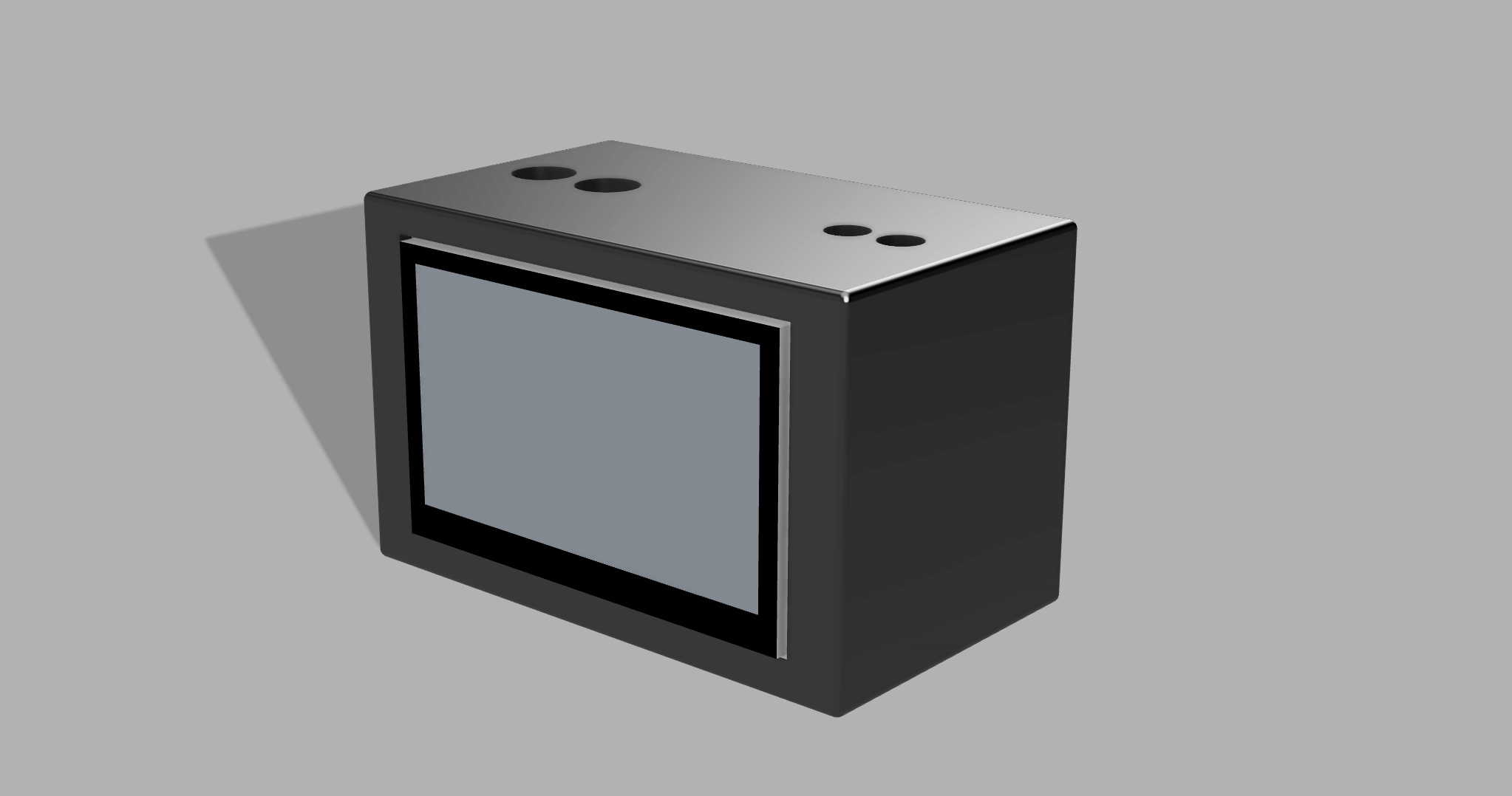
Image & Video Compression
For this week, I explored image and video compression techniques to understand how large design files can be optimized for web documentation. The goal was to observe how file size and quality change with compression tools.
Image Compression
Screenshots and design visuals often result in very large files, especially when exported directly from design software. To understand how compression works, I tested one of the commonly used image compression tools.
TinyPNG (Web-based)
TinyPNG is a simple online tool that compresses PNG and JPG images using lossy compression (slightly reducing the quality to get smaller size compared to original photo).
It is good for website documentation because it does not require any installation and is quick. https://tinypng.com/
How I Used TinyPNG
- Opened https://tinypng.com/
- Dragged and dropped a screenshot or design image into the browser
- Waited for the compression process to finish automatically
- Downloaded the compressed version of the image
After testing, I realized:
Visual quality stayed almost identical.
Text, edges, and design details remained readable.
File sizes were reduced significantly after they were compressed. From around 1 mb to 400-300 kb. This small change by itself would make a huge impact when lots of pictures are present in your repo.
Extra things I learnt:
- Exporting images as JPEG instead of PNG would reduce the file size.
- Resizing images to more reasonable dimensions instead of keeping full size screenshots
- Reducing image quality slightly (for example, around to 60–70%) while exporting can significantly reduce file size while keeping the image clear.
Video Compression
Raw screen recordings and short videos can easily become very large. To explore video compression, I tested exporting and re-encoding short clips using Handbrake.
HandBrake (Open-source)
HandBrake is a free and open-source video transcoder that allows detailed control over video compression settings. https://handbrake.fr/
How I Used HandBrake
- Opened HandBrake
- Imported a short screen recording or video file
- Selected MP4 as the output format
- Chose the H.264 (x264) video codec
- Adjusted resolution (for example, 1080p or 720p)
- Trimmed the videos to keep only the relevant sections
- Lowered the quality slider to reduce file size (Higher the number on the slider, lower the quality. 30-20 is ok)
- Exported the compressed video
Through these test, I observed that:
- Videos became much more smaller in size
- Playback remained smooth
- Screen content was still clear enough for documentation
What I Learned from Compression Testing
By testing TinyPNG and HandBrake, I learned that:
- Raw images and videos are often much larger than needed
- Simple compression tools can drastically reduce file size
- Compression is KEY for fast loading, less space documentation
This exploration prepares me to use appropriate compression techniques for future weeks when publishing larger numbers of images and videos.
2D Design
Raster and Vector Design
The main difference between vector and raster images is that rasters are pixel-based, while vectors are created using mathematical formulas for lines, points, and curves. If you zoom in to a raster image, you will begin to see individual pixels, which can make the image look grainy or blurry.
Example Raster(Pixel Based) Tools:
- GIMP (Open-source)
- Krita (Open-source)
- Adobe Photoshop
Example Vector Tools
- Inkscape (Open-source)
- Adobe Illustrator
- Linearity Curve
- Vectr (Freemium)
Testing out Raster and Vector Tools:
I wanted to test out raster and vector tools. To make a solid comparison I chose Adobe Photoshop and Adobe Illustrator since they are both Adobe’s products.
Adobe Photoshop (Raster)
For the raster-based part, I focused on sketching the overall look of my clock, which includes a screen and buttons on top. I created the visual layout in Adobe Photoshop to guide people how the final device will look. This design was exported as a .jpg, and it is only for planning, not for fabrication. Below is the final Photoshop sketch of my device:
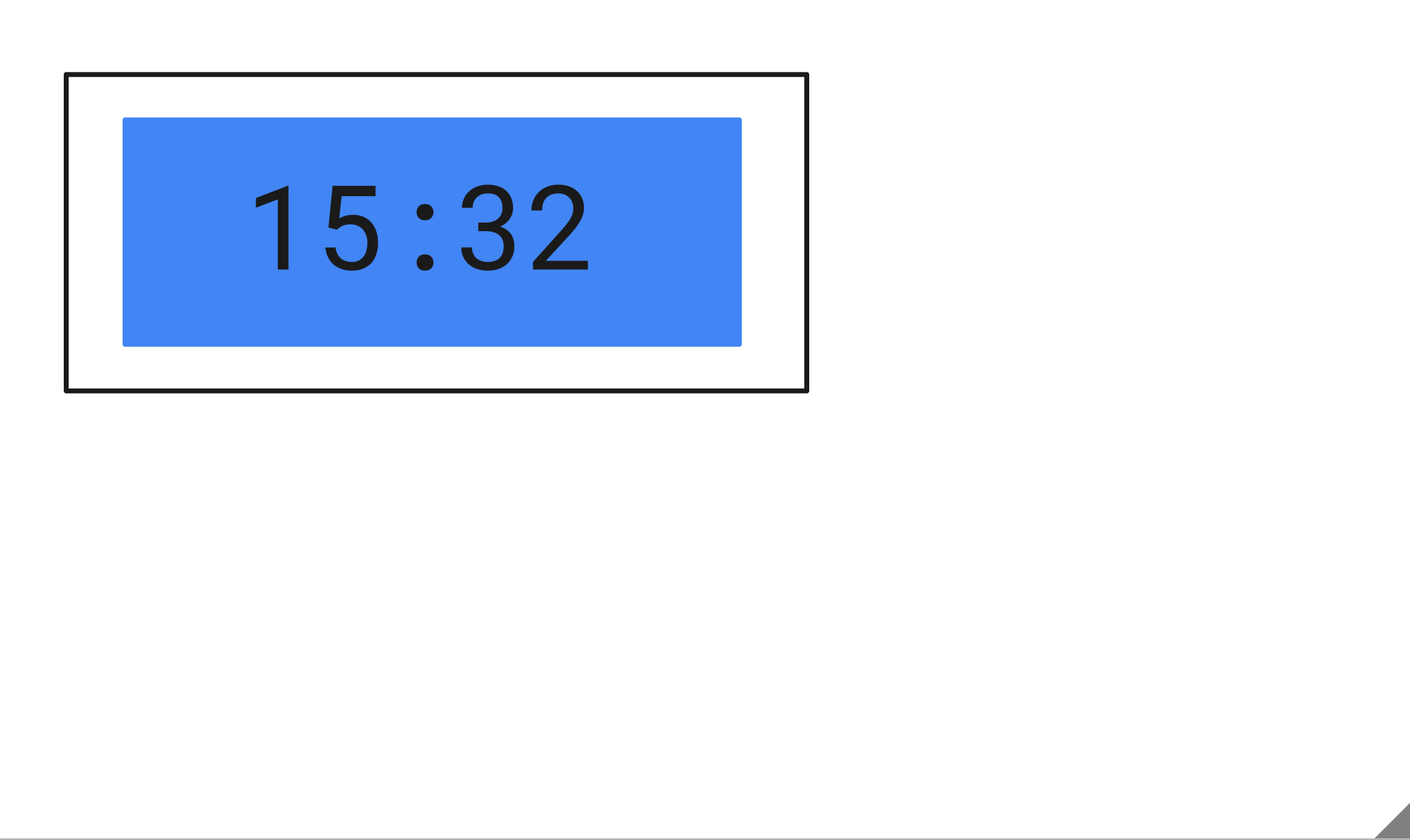
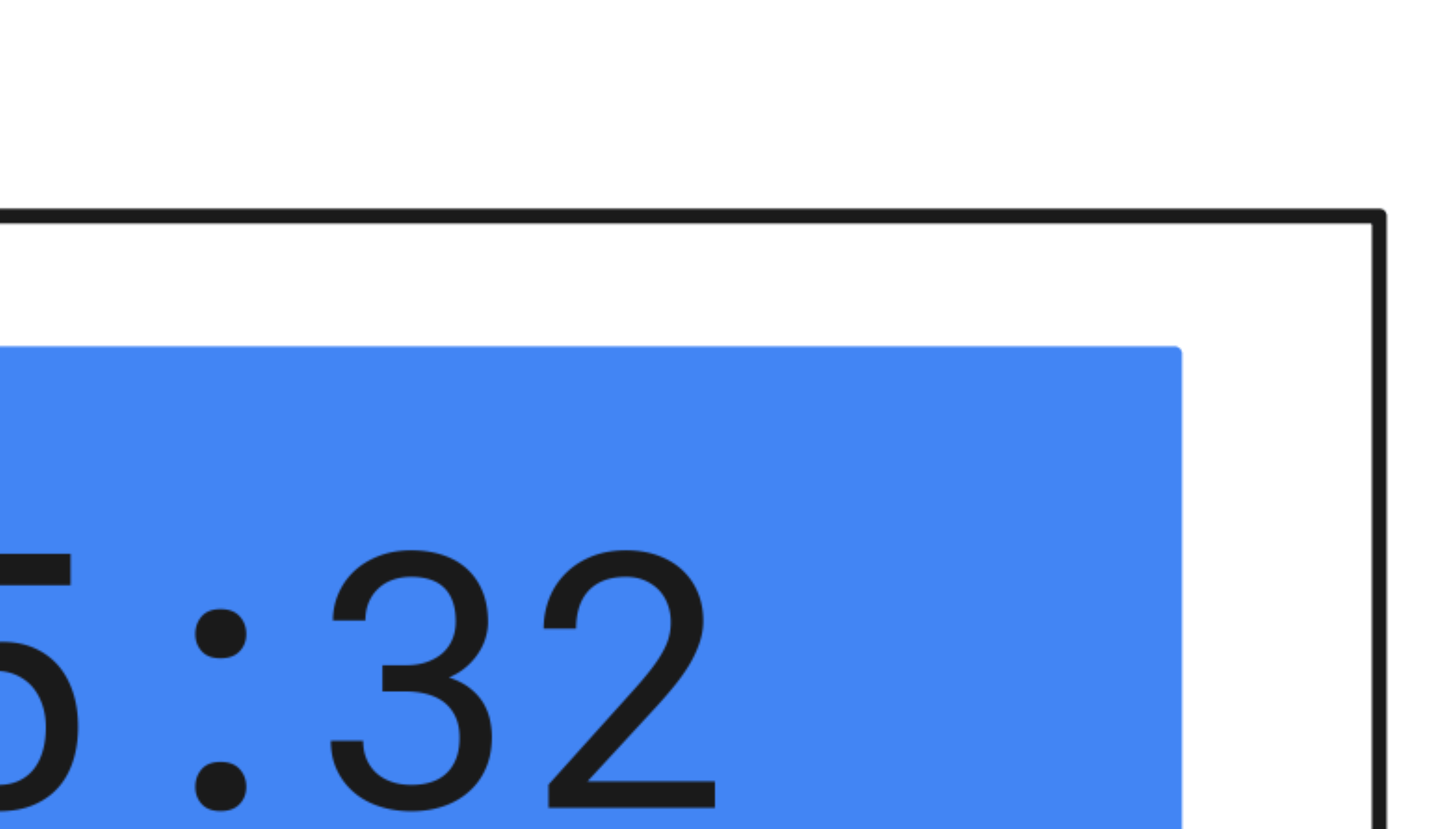
It is more pixelated as you zoom in:
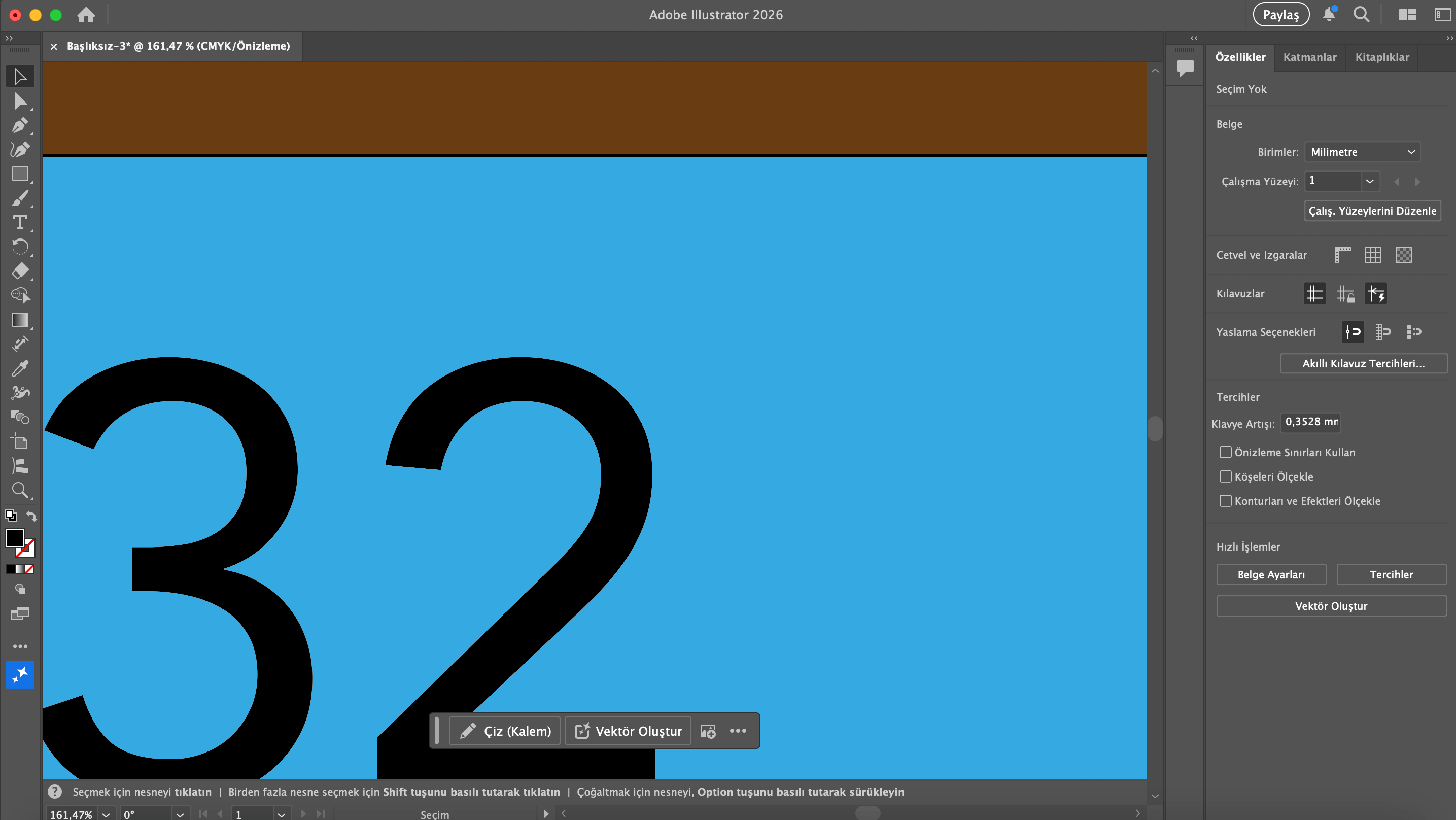
Adobe Illustrator (Vector)
For the vector based part, I worked on a design that can later be exported as an .svg and actually fabricated. This helped me clearly see the difference between raster and vector software:
- raster tools are better for visual design,
- vector tools are used for precise fabrication.
In this design, I added cut-out section for the screen as this design might be the front plate of the clock and it might be used for fabrication later on. There couldn’t be any sketches for buttons because it would have been silly to have them on this 2D sketch which might be fabricated using laser cutting machine.
Below is the final Illustrator design of the device:
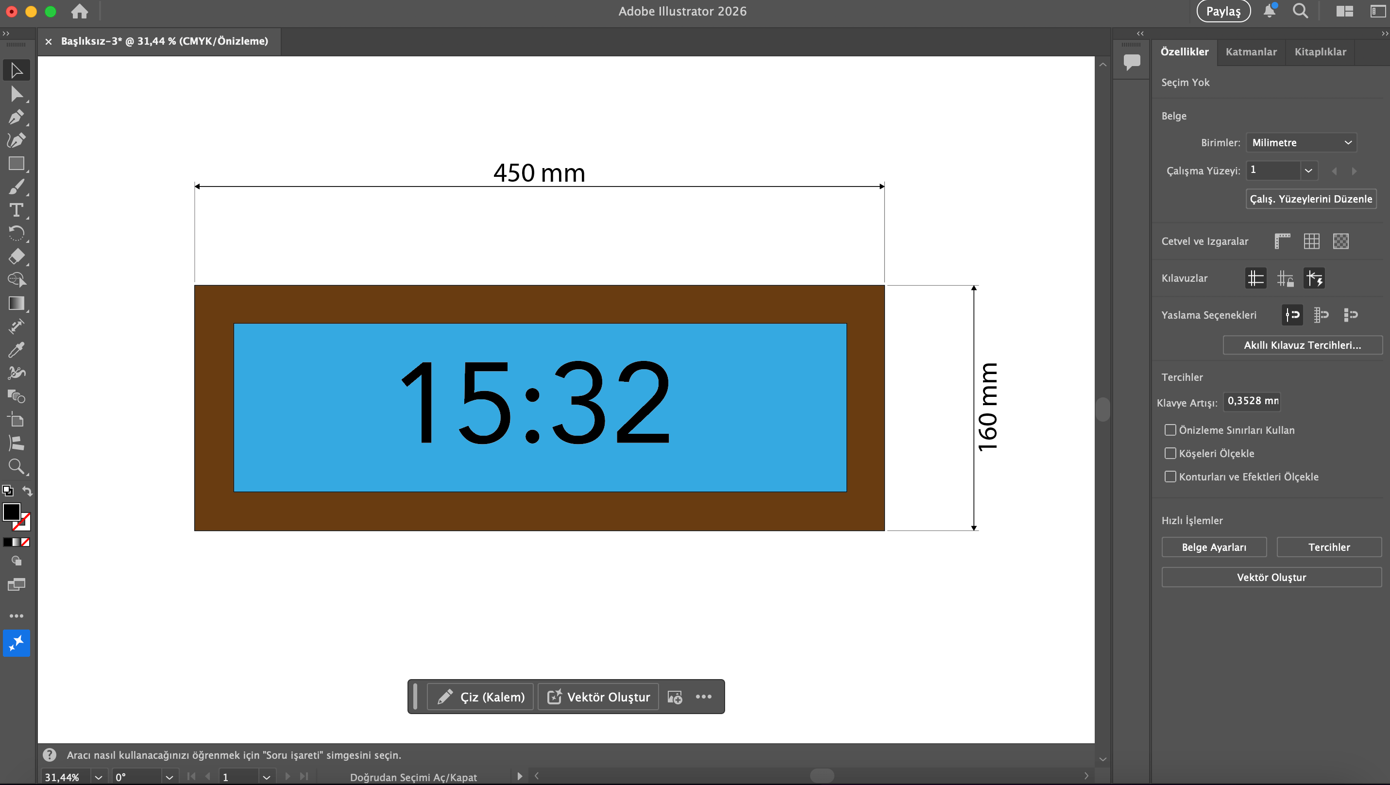
It’s quailty stays the same as you zoom in:
3D Design
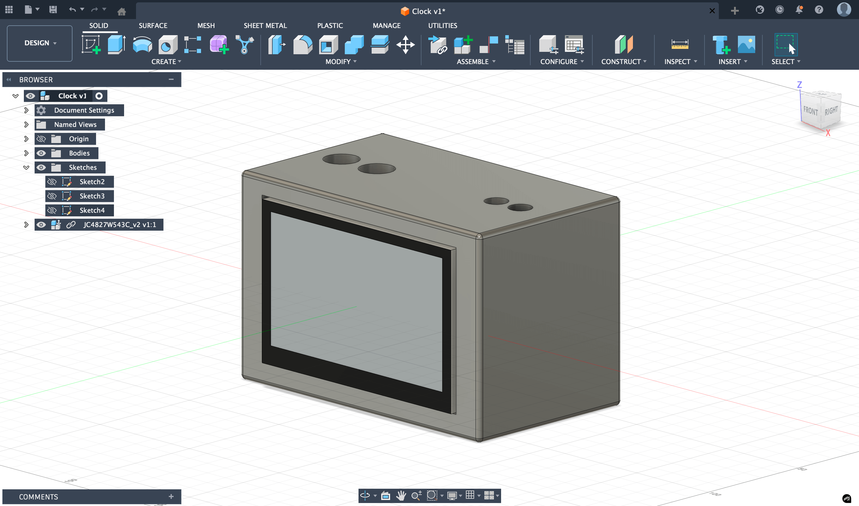
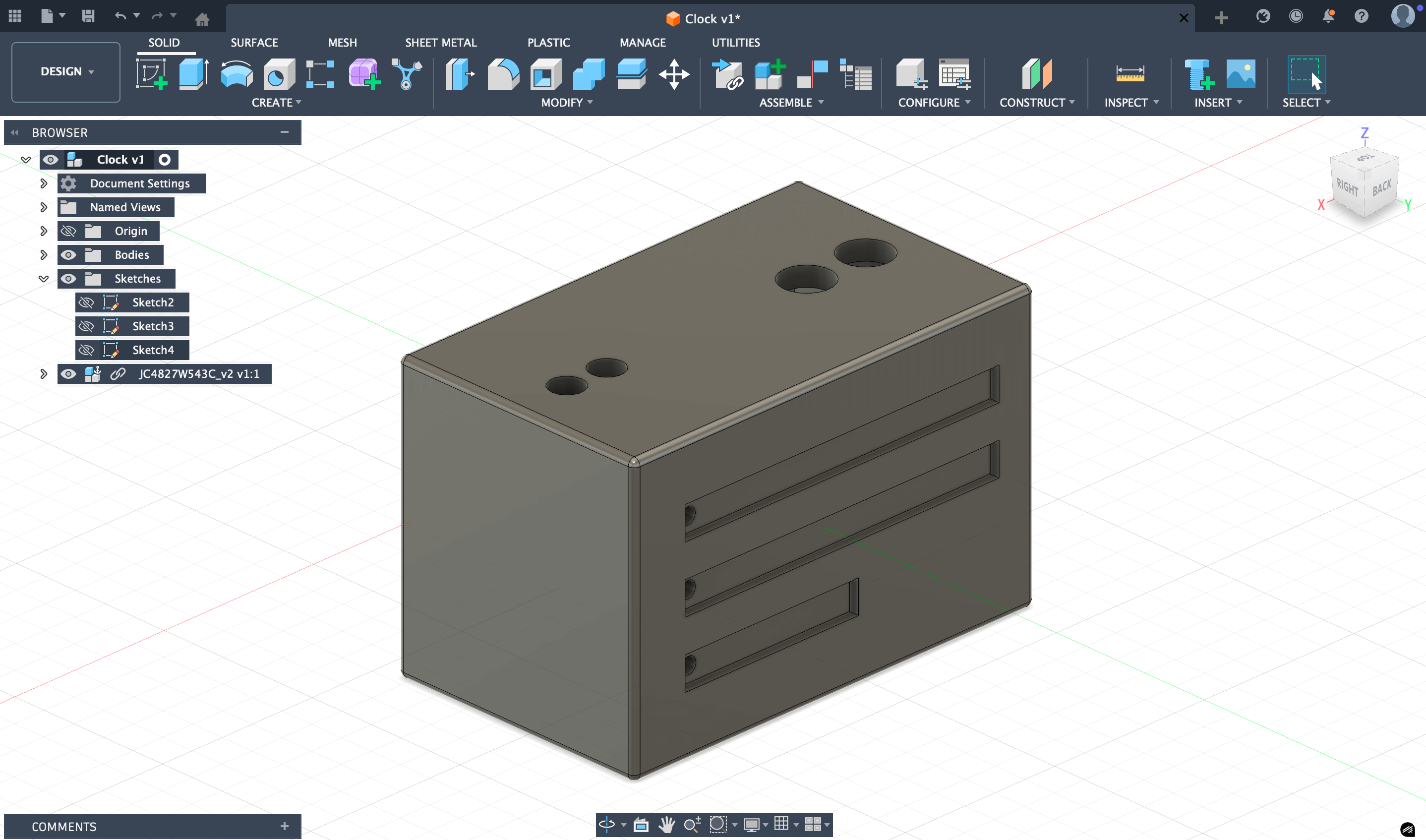
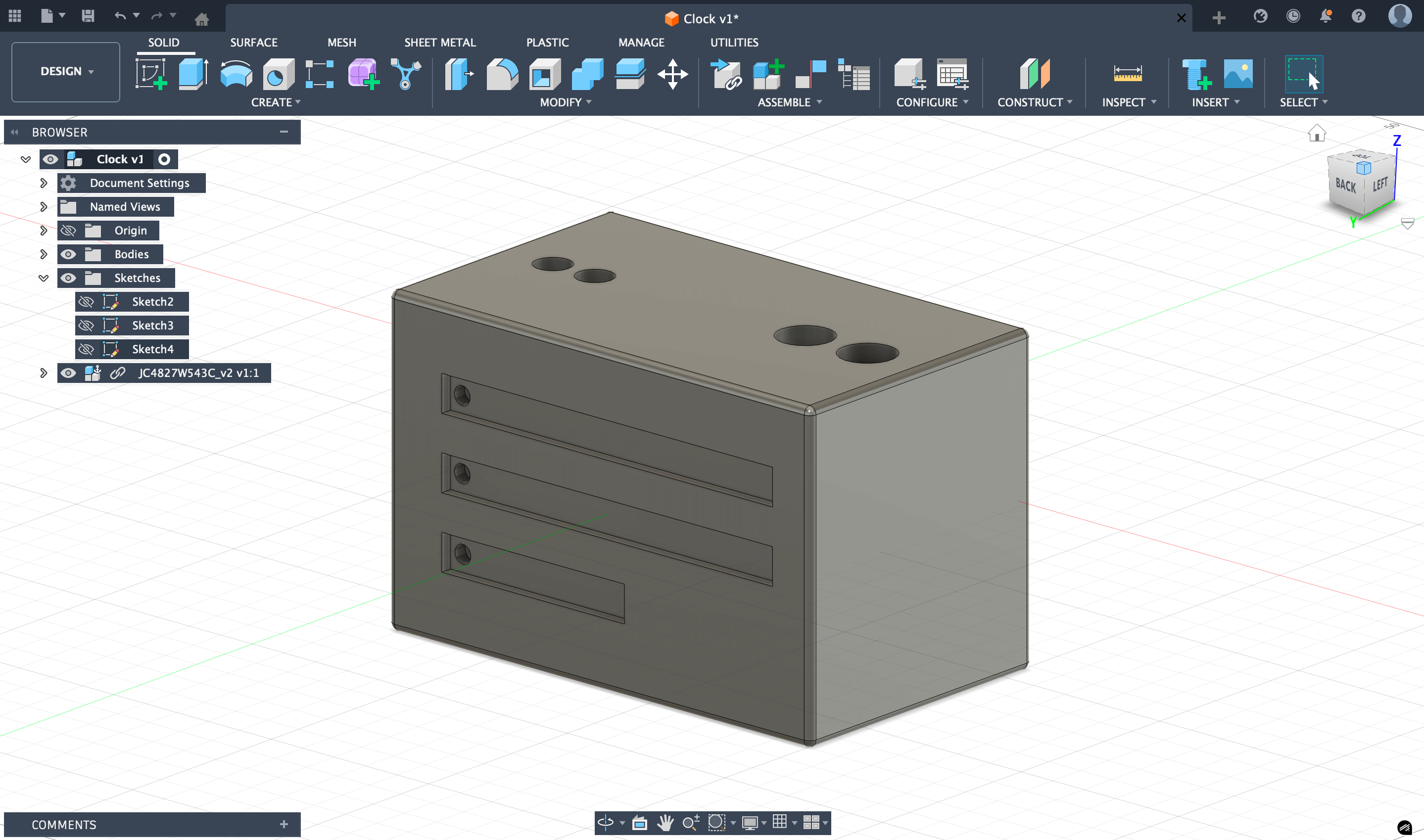
For 3D part, I designed the clock in Fusion 360. I was already familiar with the software, but I still went through several redesigns as I refined the overall shape, button placement, and LED layout. Fusion 360 made it easy to visualize the device in 3D and adjust the model multiple times.
The device includes:
- a replicate of the front-facing screen,
- several holes for the buttons and knobs on the top,
- RGB LED strips openings on the back and bottom,
- and an internal space for the electronics.
I began by creating simple 2D sketches for each face of the device: the screen cutout on the front, the possible button and knob openings on the top, and the LED slots on the back and bottom. After defining these sketches, I extruded the main body and did not forget to create a hollow interior for the electronics.
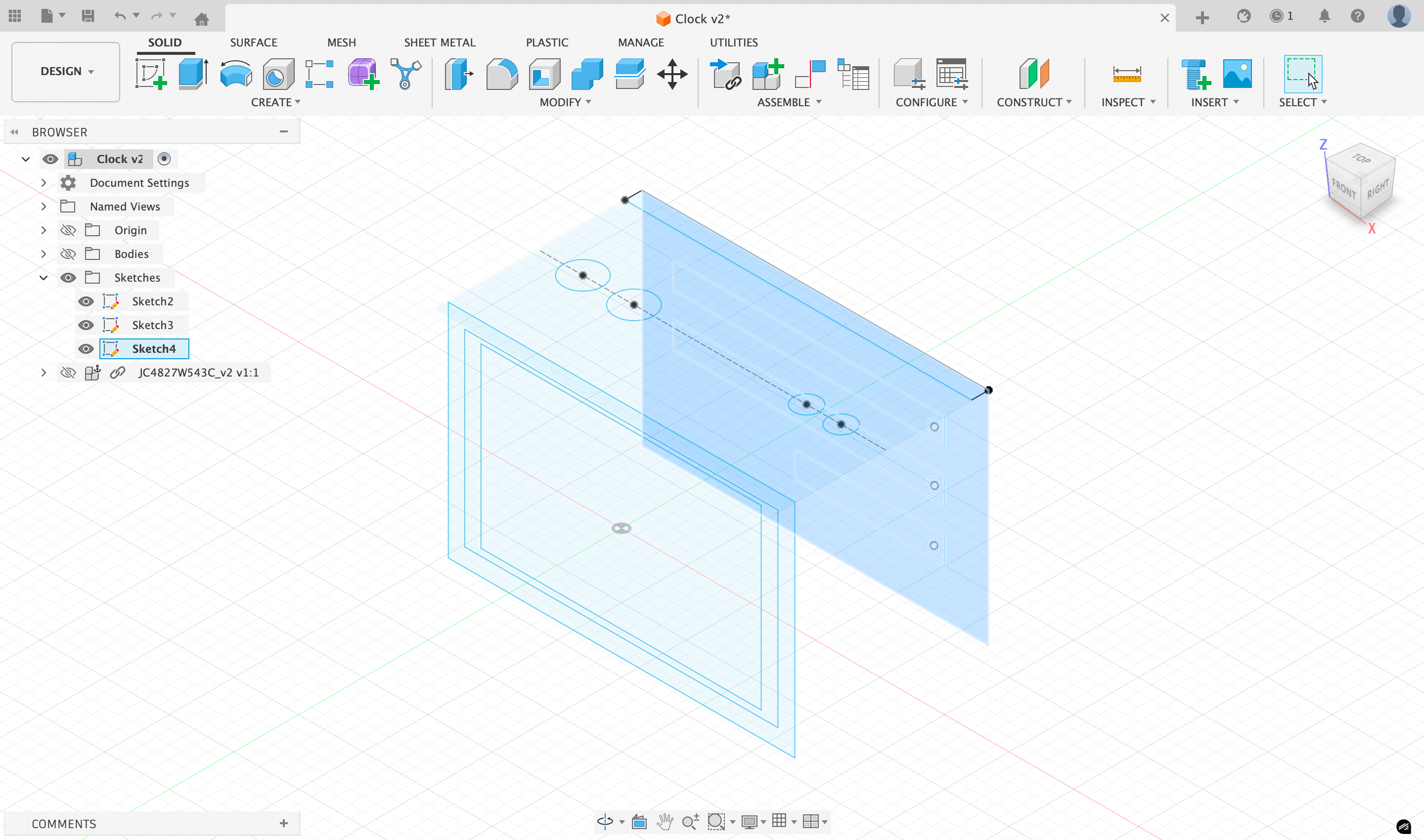
Next, I added the openings for the buttons, knobs, and LEDs, adjusting the dimensions several times to match the real components.
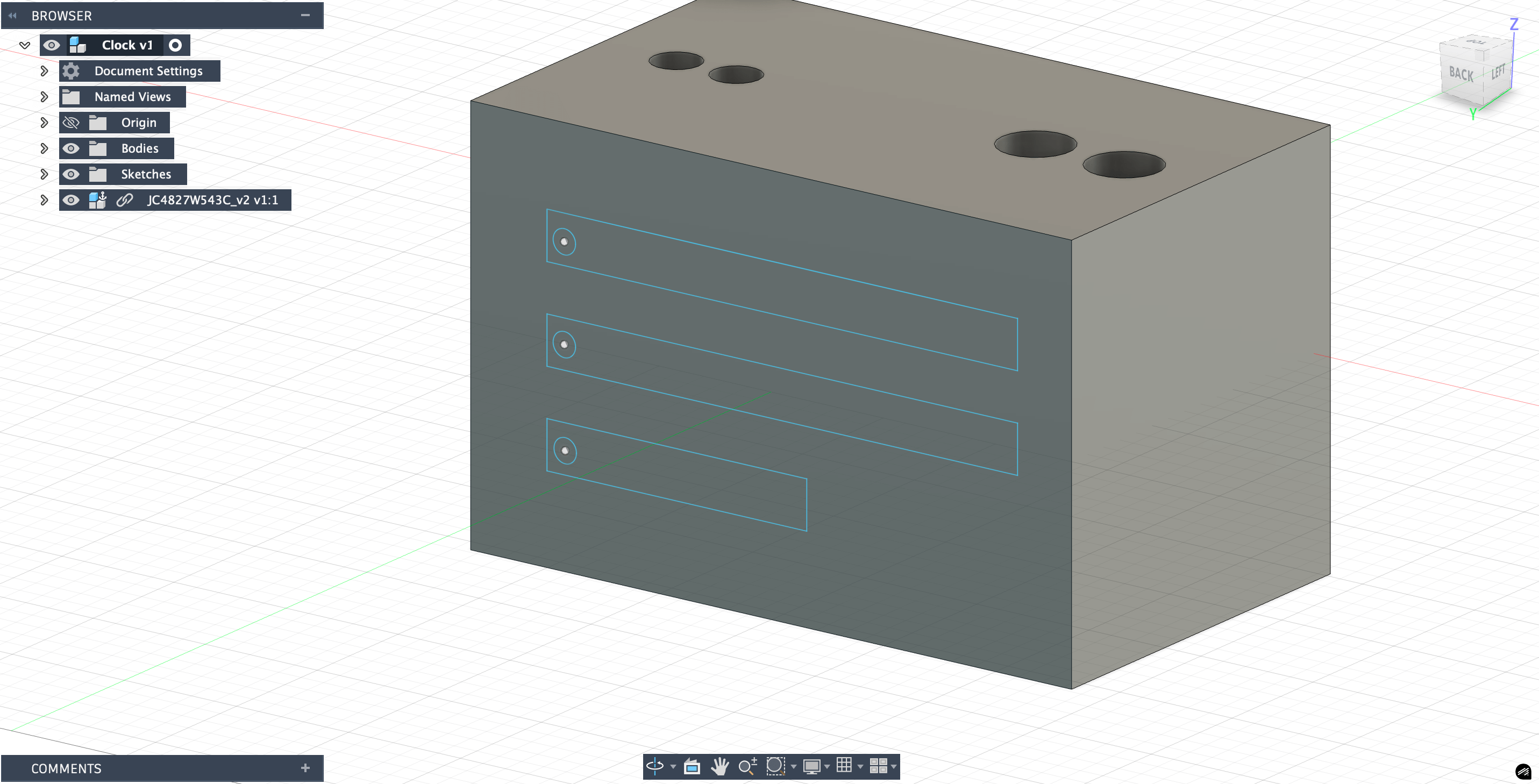
To make sure everything fit properly, I imported an smaller example model of the screen from GrabCAD and placed it inside the design using the Joint tool. This allowed me to check clearances, alignments, and the overall proportions of the device. I also included small internal supports to hold the screen in place and ensure stability once assembled.
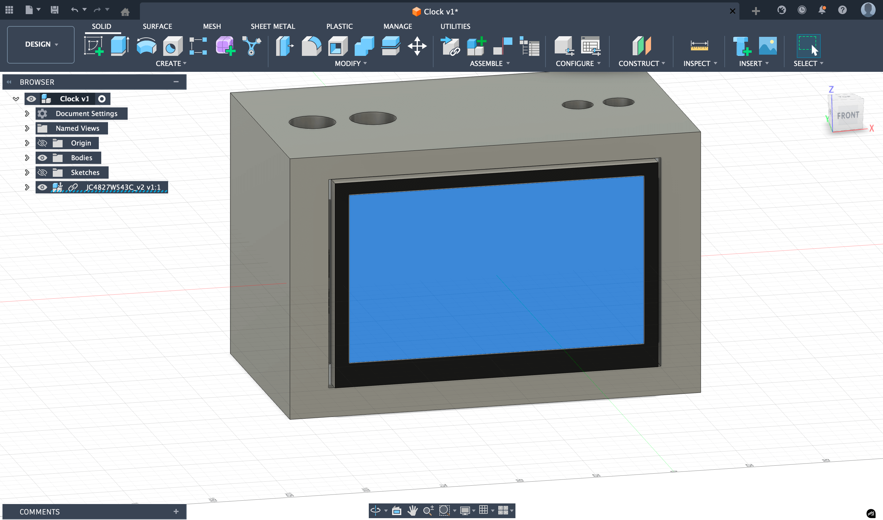
Throughout the process, I refined the appearance of the enclosure by adding fillets (rounding edges) and modifying the overall proportions based on how the model looked in the 3D view. The final model includes a display on the front, several buttons and knobs arranged neatly on the top, RGB LED strips on the back and bottom, and a smooth enclosure with rounded details. Once the design was complete, I exported it as an .stl file for slicing and 3D printing.
Here are the final photos of the Fusion 360 design:
Reflection
This week helped me see the difference between visual planning and fabrication ready design: raster is fast for ideas, while vector and 3D modeling require precision.
I also learned that compression is an important thing, because small size savings add up when documentation grows. Next week, I want to make my design more parametric and still keep an organized workflow for media and files.